A Study of Seismic Retrofitting Techniques on Existing Structures
Info: 7939 words (32 pages) Dissertation
Published: 13th Dec 2019
Tagged: Construction
Abstract
Earthquake engineering is a subject where a person can be overwhelmed with information but still crave for knowledge due to its unpredictable nature. Earthquakes are a natural repetitive occurrence on planet earth, which due to its devastating impact, have caused a lot of damage to structures and caused loss of life. Therefore, engineers, scientists and geologists were required to take action and one of the many first steps was to identify the regions of seismic activity. The argument in this essay is not how to prevent earthquakes as that is out of the control of humans but how to minimise the damage and deaths caused by them by designing better buildings. The challenge to first achieve this goal was by engineers in America, where in 1906, in the state of California, due to the frequent earthquakes in the state, building design codes and safety standards were established. These design or seismic codes have helped to reduce the damages caused by earthquakes. Therefore the solution for people in active seismic zones is to adhere to the seismic codes strictly, designed by engineers in order to help strengthen buildings and reduce the loss of life when an earthquake occurs.
Chapter 1: Introduction
1.1. Objectives and Purpose of the study
The leading resolution of this report is to investigate earthquake resistant techniques in building design and to increase one’s knowledge in the seismic restoration of existing structures. The main criteria of the study include:
- Inspection of the effects earthquake have on structures.
- Detailed evaluation on the techniques used to counter earthquakes.
- To explore retrofit methods and its successions for consolidation of existing structures.
- To compare different case studies of earthquake strengthening methods, analysing the reason for each choice of earthquake strengthening method
- To create a model of house/building and suggest appropriate earthquake performance strengthening measures.
1.2. Outline of Counter Earthquake Design
The majority number of earthquakes happen through the crust in fault zones moving abruptly. Strain energy is released due to this abrupt movement. Thus, through the crust around the fault are makings of seismic waves. These waves instigate the surface of the soil to vibrate together with the ground which is the leading worry for engineers when designing structures to resist earthquakes. Over time seismic hazard maps have been created using two main sets of data, which include the past accounts and geographical records of earthquakes. This helps to approximate the likelihood of quakes at a specific location. However, earthquakes can still occur at any time and are very difficult to forecast due its unpredictable nature.
The structural response of most loadings produce a static response, whereas the structural response of an earthquake is dynamic. The section of the structure above the soil is not exposed to any applied force when the ground shakes during an earthquake. The inertia of buildings (resistance of buildings to any change in its state of rest) is what produces the earthquake forces as they react to ground motions induced by the earthquake. ASCE 7 has a design spectrum proposed to predict the response of a structure to an earthquake. The initial move towards making a design response spectrum are the illustrations of the highest reaction of a construction combined with accurate ground movement. Typically orchestrated by experts through showing a response function against response period. The hypothesis behind this depends on the reaction of a solitary level of opportunity framework, for example, a solitary mass associated with a spring or a one-storey framework with its rooftop filled with correct amount of mass. One way to resolve the reaction ranges for a solitary ground movement are the rescheduling of timed reaction of the exact land movement for an extensive variety of occurrences and general quantity of damping,
On the other hand, the principles of dynamic modal analysis, allows a realistic estimate of the greatest response of the diverse degree system. The method includes determining most extreme reaction of all modes at a solitary level of flexibility reaction range and afterward assessing the greatest aggregate reaction by totalling the individual reactions of all modes. In general, the aggregate reaction is generally minor since the attention of every single conceivable method of vibration is not needed.
The primary point of seismic tremor safe plan is to evade the crumple of structures amid quakes to diminish the danger of death or harm to individuals. Serious seismic tremors have a little probability of happening in structures considering the life-time and availability of the structure. Any sort of stress or strain are not accepted to surpass the limit of its elasticity, (due to the standard structural plan) when reacting to ground movement. Nevertheless, in tremor strategies, structures can strain past its flexible cut-off because of ground movement. For structures to contradict such seismic tremors flexibly, it would require a horizontal load opposing framework. Amid a staggering quake, the structure is inclined to encounter inelastic distortion and must depend on its flexibility and hysteric vitality scattering ability to forestall fall. Present day structures are intended to be sheltered under ground shaking by keeping away from fall. An adequate seismic tremor designing outline requests the engineer to control the reaction of the building. This is finished by picking a favoured reaction mode, embracing inelastic disfigurements to adequate zones by conveying required itemising and maintaining a strategic distance from the improvement of undesirable reaction modes which could prompt building breakdown.
Numerous existing structures that were worked by past outline codes and benchmarks are frequently discovered helpless against quake harm because of deficient specifying, thought little of seismic tremor loads or material decay over time, and so on. As new developments are expensive to construct and recorded significance of ancient structures has driven building proprietors to remodel instead of supplant the current structures. This has made governments actualise required seismic reinforcing regulations as compulsory. Furthermore, seismic restoration systems for structures need to incorporate together the assessment of the current horizontal force opposing components of the structure and the expansion of new components in areas that require urgent attention.
The addition of retrofit methods to a structure will result in a rise in the stiffness of the structure and a little increment in mass. This higher mass shortens the vibration period of the structure. Thus, this consequents in an expansion in potency and malleability of the structure. In this way, techniques of retrofitting will be effective when the intensification of the durability and ductileness of a building is unrivalled to the requests enforced through quakes.
1.3. Scope of Work
The dissertation is structured into five different chapters. The key chapters of the research are summarised as follows:
Chapter One: The introduction and general discussion of research topic is carried out.
Chapter Two: An introduction into earthquakes and the most vital literature related to seismic strengthening techniques is examined. The discourse depends on the seismic constrain opposing frameworks in structures and the plan approach against horizontal loads.
Chapter Three: The methodology of the research is outlined with reasons for the route taken and the limitations of the project.
Chapter Four: Case studies of different retrofit methods applied to existing structures are explored and the achievability of retrofit methods are examined.
Chapter Five: The research is summarised and a conclusion of the important discoveries is made. The probable future projects in seismic strengthening are also outlined.
Chapter 2: Literature Review
2.1. Earthquakes
2.1.1. Why do earthquakes occur?
An earthquake is established as ground shaking which is caused by the sudden release of energy in the earth’s crust (Sarno and Elnashai, 2008). They are considered as a natural hazard that occurs unpredictably but the effects of it can be devastating (Alexander,1993). The earth’s tectonic plates are always moving at a very small speed. It is when the tectonic plates get stuck on its edges due to friction and the stress overcomes this friction, an earthquake occurs (USGS 2016). The earthquake discharges energy as waves that move within the earth’s crust and causes the vibration of ground.
Over time scientists and engineers could record details on earthquakes as technology advanced using standardised seismometers. The intensity of an earthquake is measured on a Richter scale and usually anything with a rating below 5.0 on the Richter Scale does not cause any significant damage. It is earthquakes above 5.0 (does not typically reach higher than 8.0 in a period of 1000 years) on the Richter scale that cause a lot of damage and produces problems for engineers. It is important to find the boundaries of the tectonic plates as these areas are where seismic activity regularly occurs. Figure 1 below shows the world map, with the plate boundaries labelled. The zones connoted in red in the guide underneath show the spots where the highest seismic movements are conceivable.
Seismic peril is computed as a ‘peak ground acceleration (in units of m/s2) with a 10% likelihood of being surpassed inside a 50-year time span’ (Denton, P 2015). This information about the reasonable power of shaking is the thing that specialists require to dissect how solid structures inside a territory should be. The UK for the most part has an estimation of under 0.4 m/s2 while parts of Greece have values as high as 5 m/s2. Therefore, areas of greater seismic hazard have stricter building regulations to design structures that will have a chance of withstanding an earthquake like in California.
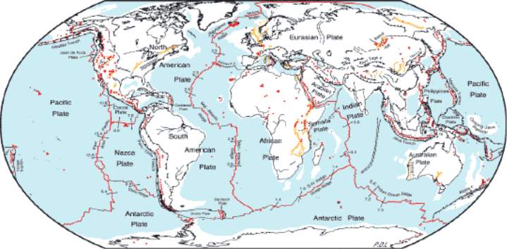
Figure 1 – The world map illustrated with plate tectonic boundaries (Source: Earth Observatory 2000)

Figure 2 – The boundary of the Eurasian plate in Iceland (Source: By Author, 2016)
2.1.2. What impact do earthquakes have on buildings?
The greatest number of earthquakes occurs in Asia, America, Caribbean Islands and Europe but earthquakes do not actually cause the death of people but the falling debris and buildings do (Hyndman and Hyndman, 2012). Therefore, it is important for engineers to use innovative ideas on how buildings should be designed and built to withstand earthquakes. Geologists order seismic waves into two classifications: body and surface waves. Body waves, that incorporate P and S waves, go through the earth’s core. The P waves compress and expand material and the S waves move material up and down (William, H 2016). At the point when a seismic tremor happens, P waves hurl through the planet at first, trailed by S waves. After this, arrives the slower surface waves. It is this surface waves that causes more destruction as they can travel longer separations and make structures be harmed. On the off chance that seismic tremors just moved the ground vertically, then structures will endure less as gravity would have the capacity to withstand this.. However, as there are extreme horizontal forces on buildings during earthquakes, it is this that causes buildings to collapse. Analysing the behaviour of structures during earthquakes is important for engineers as this will help in designing buildings and structures to withstand earthquakes. Structures can be designed to withstand these surface waves and therefore increase the chances of it to resist earthquakes.
2.2. Seismic Codes
2.2.1. What are seismic codes?
Seismic codes are a necessary requirement that can make structures effectively more resistant to seismic forces during earthquakes, as defined by the Federal Emergency and Management Agency (FEMA). The seismic necessities are likewise basic in justifying a steady direction in planning and development structures that will effectively confine seismic dangers (FEMA, 2015). Therefore, in the last 40-50 years’ seismic codes and building regulations have been developed and established in many parts of the world, specially in countries that are more prone to earthquakes, to build infrastructure with satisfactory seismic designs to tolerate the earthquake forces. For engineers when designing, seismic codes is not the only requirement. There are requirements to design buildings earthquake, fire, wind and flood proof. Therefore, the aim should be to consider all factors when undertaking the design. It can be difficult to implement seismic codes sometimes as there may not be enough funding or enough risk in certain areas, hence when an earthquake occurs a lot of damage is caused. Therefore, it is important to put the views of local communities into consideration when using seismic codes for the design of buildings.
2.2.2. Eurocode 8
A seismic provision first published in 2004 and adopted in 2010, this is a state of the art third generation seismic code that includes latest design concepts including energy dissipation and displacement-based analysis methods. It is the first seismic code designed in Europe and it is also the only seismic code that has a single code (part 3) that deals with existing structures. In the UK, there is generally no requirement to consider seismic loading as the UK is an area of low seismic activity. However, this does not mean that Eurocode 8 is not used in the UK, as some structures, due to their location, form or function warrant a need for seismic design. An example of this nuclear power stations (due to its radioactive nature, to save lives in natural disasters, nuclear power stations should be designed as earthquake proof). If the seismic design codes are not applied correctly, it results in more damages to buildings.
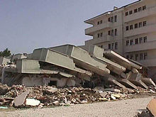
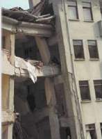
Figure 3 – Pictures illustrating the damage of the 1999 Turkey earthquake (Source: Britannica, 2013)
The above figures show the damages caused when seismic design codes are not followed correctly. For example, the picture on the left shows the pounding effect of buildings with the building on the left pounding into the building on the right. Seismic design codes like Eurocode 8 help to design to avoid this type of damage and many other types as analysed later in the research.
2.2.3. ASCE 7
American Society of Civil Engineers has developed a very advance seismic code to design structures that will withstand earthquakes. California, in America, first faced the reality of earthquake problems in 1906 following the San Francisco earthquake, urging engineers to create building design seismic codes and safety standards. The code has developed many times over time and many changes have been incorporated into buildings and constructions following the California earthquakes in 1933 (Long Beach), 1971 (San Fernando) and Northridge in 1994. Once it was established that California will always be prone to high seismic activities, the need for instituting seismological awareness increased and therefore targets were made. These targets included the necessity to form building design codes to eradicate the damages caused by earthquakes (including damages to property and life). Over time the seismic code of ASCE 7 has been developed and in one way it differs from Eurocode 8 includes that it is suitable for the design of buildings more than 20 storeys, whereas Eurocode 8 is only suitable for buildings less than 20 storeys tall.
2.3. Seismic Retrofitting
2.3.1. What is Seismic Retrofitting
The construction and design of new structures for earthquake protection is now a common practice in areas of high seismicity, due to strict design codes like the Eurocode 8 and ASCE 7. However pre-1998 many structures have been constructed, where earthquake protection was not taken into consideration. Therefore, it is a challenge for engineers to modify existing structures to provide earthquake protection for it. Seismic retrofitting is the alteration of present structures to make them more resilient to seismic activity, ground motion, or soil failure due to earthquakes.
Researchers and engineers discovered a series of hypotheses in seismic design that was entirely established. Firstly, ground movements from earthquakes produce inertial loads that quickly alter over time. Hence, in this subject engineers conduct computations using a unit of time which often is seconds. The calculations also involve periods of vibration and its opposite, frequencies; velocities and accelerations. In numerous other engineering problems, such as designs of gravity loads, there is no unit of time applied.
Secondly, as earthquakes forces and the structural responses are very unpredictable, probabilistic consideration is significant in this study. (Benjamin & Cornell, 1970). How often an earthquake occurs, its level of importance on the Richter scale, dynamic reaction of buildings and its features of rupture surface is not envisaged with certitude. Techniques of statistics and probability are necessary to incorporate due the ambiguous nature of earthquakes and its effects on the structural performance evaluation and design.
Thirdly, an essential theory that differentiates this subject, is the fact that earthquake loading can be so enormous that the constituents used in buildings frequently need to be proposed to act in-elastically. Hooke’s Law mentions that stress is proportionate to strain. However, outside of this point, behaviour turn out to be intricate and difficult to analyse. A lot of the experimental and analytical studies examining inelastic behaviour commenced in the early 1960s (Newmark & Veletsos, 1960).
2.3.2. Characteristics required in structures to resist earthquakes
The government of the United States, through the (National Earthquake Hazards Reduction Program) NEHRP have recommended that the following features are required in the design of structures to warrant that the structure can oppose earthquakes. These include:
Continuous Load Path
This is an essential feature in the design of structures for seismic protection. All parts of a structure, incorporating the non-structural sections need to be held together to produce a continuous load path. This is so the structure can transfer the inertial forces caused when the ground shakes during an earthquake, from the point of initiation to the ground.
Ductileness and Strength
This provision ensures buildings should have an acceptable amount of ductility and strength to withstand impairment when burdened with excessive load also being able to accept load without failing. These properties of a structure are crucial to endure damage without falling over. As it is the falling debris that takes innocent lives in an earthquake, damage to a building without collapse fulfils one the requirements of seismic retrofitting. Structural elements are designed to provide sufficient strength to support anticipated loads without failure. They must also have enough stiffness so that they will not deflect excessively under these loads.
Soil and Foundations
It is critical to guarantee foundation stability in areas of high seismicity. This is important as the foundation of a building maintains the mass of a structure and ought to in this way have the capacity to withstand seismic tremor actuated forces that regularly transfer huge horizontal forces between the structure and the ground. It is trusted that the steady foundation can oppose both transient and permanent ground disfigurements without initiating extreme movements in the upheld structures. Additionally, in a few sites where there is liquefaction or parallel spreading, arrangement for vertical bearing is encouraged to bolster or reinforce the foundation underneath the liquefiable layer of the soils. Keeping in mind the end goal to accomplish this, the NEHRP recommends a deep foundation with bored shafts or driven piles since it aids the liquefiable soil to be dealt with for seismic tremor liquefaction assurance before raising a building structure (Bolton Seed, 1977). Subsequently, in a few sites that are liable to lateral spreading, vertical bearing is relied upon to strengthen the foundation underneath the layers of soil that are liquefiable. The foundation is required to be sufficiently deep with bored shafts to stop vast parallel movement of soil that regularly happens when there is solid shaking of the ground. Hence, singular foundation components are prescribed to be secured firmly together to avert structures being torn separated during an earthquake.
Stiffness and Toughness
It is recommended by NEHRP that structures need to have sufficient stiffness and toughness. Buildings are susceptible to vertical and lateral forces due to the shaking effect in an earthquake. This kind of force regularly moves structures horizontally resulting in an uprooting in defenceless structure and can bring about huge detriment where there is an absence of stiffness and toughness.
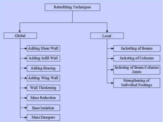
2.4. Seismic Retrofitting Techniques
There are many different methods of strengthening existing structures. Previously, seismic retrofit was principally connected to accomplish the safety of the public, with building solutions constrained by financial and political contemplations. Nonetheless, with the improvement of Performance Based Seismic Engineering (PBSE), a few levels of execution targets are perceived:
Public safety only. The objective is to secure human life, guaranteeing that the structure won’t crumple upon its inhabitants or bystanders, and that the structure can be securely evacuated. Under extreme events of earthquake occurrence, the structure might be a complete economic loss, requiring demolition and replacing.
Structure survivability. The objective is that the structure, while staying harmless for exit, may require broad repair (yet not replacing) before it is largely valuable or deemed safe for occupation. This is normally the most minimal level of retrofit technique applied in the construction of bridges.
Structure functionality. Essential that structure is undamaged and the structure is undiminished in utility for its main application. An abnormal state of retrofit, this guarantees any required repairs are just “corrective” – for instance, minor breaks in mortar, drywall and stucco. This is the base worthy level of retrofit for hospitals.
 Structure unaffected. This type of retrofit is favoured for notable structures of high social centrality.
Table 1 – Classification of Retrofitting Techniques (Source: Banarjee, 2011)
Seismic retrofitting techniques include the installation of new shear walls, adding an infill wall, including braced frames, wall thickening, mass reduction base isolation, mass dampers, jacketing of beams and columns, strengthening of individual footings, external post-tensioning, slosh tank, infill shear trusses, moment resisting frames and diaphragms. Some of these retrofitting techniques are discussed in more detail below.
Shear Walls
 A shear wall is a structural system that is made of shear panels. It can be added to existing structures and new structures to resist the lateral load imposed on a structure during an earthquake. Shear walls usually covey seismic tremors downwards to the foundation of a structure. Shear walls are commonly used in the retrofitting of non-ductile reinforced concrete frame buildings and the elements are preferably placed at the exterior of the building. Structures that consist of a shear wall are prevalent in countries of high seismicity including New Zealand, USA and Chile. The construction stage of shear walls is reasonably easy and hence the shear wall can be constructed on site. Nevertheless, shear walls are an effective way of reducing the risk of structural damage during an earthquake and are also cost effective. Over time, analysing the implementation of shear walls in recent earthquakes, the appropriately proposed and comprehensive shear walls in structures have shown a good performance level. Even in the examples where a failure of a shear wall has occurred, a lot of damage includes diagonal or horizontal cracks which are effectively repaired after the quake (Paulay and Priestley, 1992).
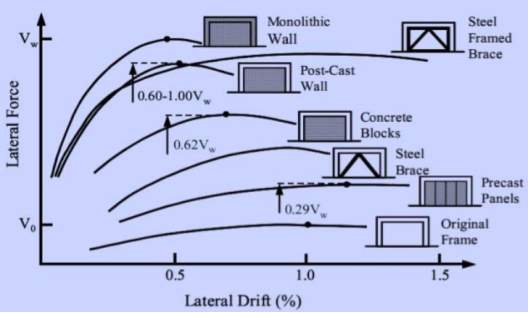
Figure 4 – Graph showing the effectiveness of shear walls and braced frames. (Source: Banarjee, 2011)
Examples of Braced Frame Retrofitting Techniques
Braced frames are analysed in more detail as it can be said it is one of the most effective retrofitting techniques.
Wood Braced Frames
The improvement of wood frame is utilised all through USA generally for private lodging. Economically, wood is a better choice of construction material since structural segments like steel and cement are pricier. As far as visual viewpoints, vast timbers have incredible preferred standpoint. Subsequently, the wooden supported edges have the extraordinary favourable position of flaunting a structural material that is likewise tastefully valued. Other than visual angles, the lightweight and high vitality engrossing abilities of wood-surrounding are vital attributes that make wood-encircling a favoured building framework in seismic tremor districts. Overviews have demonstrated that wood-frame structures meet the essential necessities for wall supporting, network and harbour, give security to their tenants amid seismic tremors (Canadian Wood Council, 2001). Posts and pillars made from wood cannot possibly be consolidated unbendingly enough to make a joint that can oppose rotation. In this way, the two regular alternatives for vertical timber components for opposing horizontal influences are shear walls and braced frames.
The wood individuals in braced frames are regularly extensive in cross area to deal with their structural loads and additionally since fire arrangements in construction laws. The knee prop appeared below shows the general placements of components for a knee brace that are needed for wooden frames. The brace helps to stop any flexibility in the joint and cause any damage to the non-structural segments. For the most part, the aim of knee bracing is to be an added aid of support to the resistance frames under adjacent loads. Also, it helps decrease the vulnerability of the segments to clasping by lessening the unsupported distance of the pillars.
The adequacy of a knee prop is for the most part subject to the solidness of the associations with the truss and post. For example, if the prop associations are fashioned hard by introducing a lot of jolts or nails. It probably might adequately oppose horizontal loading in the supports, however over-burden the truss. On the off chance that the brace links are made extremely adaptable (by introducing very few nails or jolts) the support could be inadequate.
It is hard to make the associations in a wood supported frame as solid as the individuals. It is attractive for associations with build up the full quality of the individuals so that a weak disappointment at a joint cannot suddenly happen. Because of their inalienable solidness and low flexibility, propped edges are especially powerless in serious seismic tremors. The main components that can give any noteworthy measure of vitality assimilation are the associations, and along these lines unique consideration should be paid to association enumerating to guarantee flexible conduct under huge disfigurements (Prion et al., 1999).
Light slanted props incorporated with the stud wall encircling act basically as little propped outlines, yet they tend to rapidly lose limit in the inelastic range. Cut-in props utilise bits of wood an indistinguishable profundity from the studs in the wall and are rooted between the props that’ll help the portions mark up to frame at an angle. Whist let-in props utilise a single persistent bit of lumber scored into every single stud.
The stream of powers in a timber and a steel propped edge of a similar design are basically the same under seismic tremor stacks in the flexible range. Be that as it may, the method of conduct and seismic plan theory in steel and timber supported frame is very extraordinary in the brittle range. Compared to steel, the yield points in wood aren’t much characterised. The parting, smashing, and transgression of a bit of wood in the distance characterised as inflexible doesn’t comply with an exemplary meaning of pliability (Symans, et al., 2002).
Concentrically Braced Frames
These frames are generally utilised as horizontal load opposing frameworks in structures all through America. The standard extension otherwise rooftop truss are arranged due to gravity in an upright position and traverses on a level plane, while the supported frame is loaded principally on a level plane by quake latency masses and goes about as a upright plank. Wellspring of truss’ soundness depends on fundamental triangle as its unit which is an entity used in structure that opposes basic burdens through improvement of hub strengths in its individuals. Unadulterated truss activity comes about when the powers in the individuals are adjusted to the centrelines of stuck joints. CBFs join shafts, segments, and props at basic work focuses. The supported frame is an immediate, sparing, and viable seismic arrangement.
At the point when the strain in a supported frame part surpasses its flexible breaking point, it might make the material have a lasting disfigurement and the framework cannot discharge securely towards the strain. Except exceptional tremor inelastic outline elements stand consolidated. Clasping of bars and sections can’t speak to adequate methods for dispersing seismic vitality all things considered reaction would jeopardize the gravity stack conveying limit of the structure. In this way, inelastic activity under seismic tremors should just occur in the slanting propping individuals and sufficient enumerating guaranteeing the supports can experience the normal inflexible request (Tremblay, 2001). Vital seismic outline rule is that before earthquake load increments into the inelastic range, the structure ought to steadily disfigure, permitting the construction to disseminate vitality securely instead of suddenly breaking. Moreover, seismic codes support excess. At a given story, on each line of supporting, inclining props ought to stake the horizontal weight applied in provided guidance by partaking oppose in strain whilst the rest welcome pressure. Disappointment methods brought about by the not so ductile propped outline practices must be averted and incorporate the accompanying (Bruneau, et al., 1997):
(1) The oblique bracing conveys excessively compel to the association at the pillar segment joint causing the association to disrupt;
(2) Quake brace or locks in pressure;
(3) Strain just slanting extends inflexibility, however the following redundancy of a series when repeatedly loaded in pressure, there’s sagging in the framework plus the frame must oppose a “”hammering”” impact, as well as the hysteresis circle being squeezed;
(4) If lines outline like sections (K support) otherwise pillars (V or chevron prop), the energy conveyed by the support harms the segment or shaft.
Concentric frames that are braced in steel are frequently utilised as a part of low-ascent private and mechanical structures. The high firmness of the propping has a habit of putting assemblies at the low-time frame end of the reaction range. Thusly ordinarily implies higher reaction (e.g., more noteworthy phantom speeding up) than in the long stretch range. These more prominent increasing velocities influence the structure and additionally the gear and substance. The positive angle to a solid, low-period structure, in any case, is that it tends to ensure worked in non-structural segments, for example, allotments from float actuated harm.
Eccentric Braced Frames
Similarly, like all braced edging, the capacity of the crosswise is to give firmness as well as convey parallel strengths from greater to poorer level. Capriciously propped outlines (EBFs) is a confining framework where the flightiness is deliberately arranged via a component named “”interface”” bar besides the area of inflexible conduct is deliberately and unequivocally intended to happen in pillars to not debilitate the gravity-stack opposing framework. The askew prop, in any event toward one side, is associated with the finish of the connection as opposed to the bar section joint. All inelastic action is expected to be limited to the legitimately nitty gritty connections which go about as basic breakers and can disperse connected seismic vitality without corruption of quality and solidness.
Under seismic tremor loading, eccentrically braced frames (EBFs) disperse vitality as solidified pillar fragments and turn in-elastically. These connections are normally framed from unconventionalities between two support associations, or between a prop association and segment. Interfaces in EBFs are intended to go about as basic wires, limiting frame harm inside connection locales amid over-burdening. At the point when connections are appropriately planned, the segments, supports, and shaft areas exterior the connections will continue basically flexible (Roeder and Popov, 1978). Petite connections turn because of shear yielding are more of the norm than lengthier connections which create twist pivots at individual end. These connections ideally put halfway to advance the shear yielding and maintain a strategic distance from conceivable issues identified with the associations between the shaft and the section. Plan strategies depend on limit outline standards and mean to create outlines with stable inelastic reaction of connections and versatile conduct of all other edge individuals.
Outlines with minute opposing joints react to seismic tremors in an adaptable way and has the ability for extraordinary flexibility, whereas concentric braced frames consume more noteworthy solidness as well as decreased float actuated non-structural harm. The erratically supported edge (EBF) consolidate the pliability that is normal for minute frames and the solidness related with propped outlines (Chao and Goel, 2005). The superb flexibility and vitality dissemination limit is given by 2 elements. To start with, inelastic action under serious seismic tremor loading is limited essentially to the connections which are point by point to support vast inelastic misshapenness. Second, supports are composed not to clasp paying little heed to sidelong loading. Because of a definitive quality of the connection can be precisely assessed, the creator can be guaranteed that the prop won’t clasp by outlining the support more grounded likened to the connection (Popov and Engerlhardt, 1988).
EBFs have additionally favourable position above concentrically braced frames (CBFs), as far as engineering flexibility allowed by giving bigger spaces to entryways, windows, and corridors, permitting access through the edge while supports in ordinary concentric arrangements hinder such elements.
To summarise, the literature review shows:
- Earthquakes are a natural occurring phenomenon that cause structures to fail, thus resulting in countless numbers of deaths each year.
- Public safety and structure survivability are the main aims of seismic retrofitting
- There are many different methods of earthquake strengthening techniques of existing structures
- These techniques include shear walls, braced frames, jacketing. They can be added to existing structures as well as constructing them for a new structure
- Adding braced frames is an effective method for achieving good performance for structures that undergo an earthquake. EBFs are better than CBFs in the way that they allow more flexibility for the structure and giving more space in entryways
- Other methods that have not been mentioned in the literature review (due to the word limit) also include seismic isolation, seismic damping, diaphragm, moment resisting frames etc.
Chapter 3: Methodology
3.1. Research Method
The method used in this dissertation is a desk study into seismic retrofitting techniques of existing structures. The author will critically examine the way buildings are designed to resist earthquakes and see whether the application of various retrofitting techniques help to improve the performance of a building during an earthquake. The need of seismic retrofitting techniques is increasing due to the significance of old buildings and the fact that it is cost effective rather than constructing from start. Research journals, reports and principal research findings on seismic strengthening techniques will be carefully examined to obtain reliable and necessary information on the topic material. The author will also compare different case studies to see how successful seismic strengthening techniques are in terms of building performance during an earthquake.
3.2. Research Aim
The aim of the research is to inspect the effects earthquake have on structures. And carry out a detailed evaluation on the techniques used to counter earthquakes. Also, the aim is to explore retrofit methods and its successions for consolidation of existing structures. Engineers in recent times have developed many structures that are complex and can withstand heavy earthquake forces. However, the improvement of existing structures that have not been constructed with the latest design codes, is a challenging task. Thus, seismic retrofitting is a demanding subject to analyse and the aim of this research is to evaluate the success of current retrofitting techniques.
3.2. Research Limitations
The dissertation would have been in a superior position if a practical experiment was carried out. For example, creating a reinforced masonry structure and testing it on an earthquake shake table. Then creating the same structure and adding a thin layer of veneer and metal flue and testing it again. The results could be compared and the model of the structures could be analysed using a software. However, there was no shake table available and the software of SAP2000 was not available through the university. Hence, a desk study was undertaken and case studies of retrofitting methods were investigated.
Chapter 4: Case studies
4.1. Examples of Seismic Retrofitting in New Zealand
New Zealand is a country that undergoes frequent seismic events due to the its proximity to the Indo-Australian and Pacific tectonic plates. This has resulted in New Zealand adopting strict design codes to construct structures that will undergo minimised damage in an earthquake. However, it is most of the pre-seismic code buildings that experience the most damage and hence advanced techniques of retrofitting methods are applied to existing structures. New Zealand endured a devastating earthquake in February 2011 in Christchurch that was registered as 6.3 on the Richter scale and resulting in 65 deaths.
Hawke’s Bay, 1972 Church
This is a petite one-storey structure containing generally unreinforced concrete block masonry wall with a wood-surrounded rooftop. The structure was susceptible to earthquakes because of a load path inadequacy, chiefly an absence of a rooftop and ceiling diaphragm. The unreinforced front gable wall was additionally observed and needed to perform much better under face loading. The intended accomplishment level was 67% NBS for the church. Nevertheless, extra structural segments if required, were specified to accomplish 100% NBS on the principle that the proprietor could retrofit to a much larger amount of execution later. It was possible to achieve this without enduring much additional expenses.
The church was retrofitted by adding a plywood roof diaphragm to allow for a continuous load path for horizontal loading. A 100mm thick reinforced concrete overlay was added to the front gable wall to enhance the face load execution of the unreinforced component. A current Fibrolite lined timber gable was re-lined in plywood to enhance its set up resistance and association with the new roof diaphragm and existing foundation. The total expense of the retrofit scheme in 2011 for a floor area of 260m3 was $200,000 (Reference website).
As mentioned before, it is important for structures to have a continuous load path so it can transfer the inertial forces caused by an earthquake. Clearly in the above example the church did not have a continuous load path and hence, was susceptible to earthquake damage. Therefore, the retrofit technique of adding a wood diaphragm was successful in this example as the church could withstand future earthquakes.
The Birdcage, Auckland
The Birdcage in Auckland, New Zealand, is a two-storey ancient building which was constructed in 1866. The structure consists of unreinforced masonry and includes two chimneys, a wooden suspended floor and a ridged iron roof on wood framing. Masonry structures are always susceptible to earthquake damage due to its dependence on load-bearing brick walls and this was the case with this structure. The structure also had an ostensible linking to the wooden floor and ceiling diaphragms. There was an obvious need for earthquake strengthening for this structure as it was a point of interest for tourists and was prone to seismic damage.
The retrofit of the structure took place in 2010 and included the subsequent techniques. The masonry walls needed strengthening and this was done by the posterior walls being superimposed with a shotcrete wall and drilling epoxy rods. There was a need for a plywood diaphragm to allow the structure to have a continuous load path and this was added to above the ceiling on floor two and underneath floor one. On the boundary of each diaphragm, steel triads were mounted. In order to recuperate the face load functioning of the structure, the interior walls were post-tensioned vertically. To anchor the post-tensioning of the wall into place, concrete ring beams were ordained on the edges of the walls. Carbon fibre strips were added to the chimneys to increase the flexural strength.
References
- Alexander, D (1993). Natural Disasters. New York. Routledge, Taylor & Francis Group (published in 2001)
- Benjamin, J. and Cornell, C. (1970). Probability, statistics, and decision for civil engineers. 1st ed. New York: McGraw Hill.
- Bolton Seed .H (1977) Stabilisation of Potentially Liquefiable Sand Deposits Journal of the Geotechnical Engineering Division, Vol. 103, No. 7, July 1977, pp. 757-768.
- Britannica (2013). 1999 Izmit Earthquake [Internet] Available at https://www.britannica.com/event/Izmit-earthquake-of-1999 (Accessed 18/12/16) [Figure 2]
- Denton, Paul (2015). How frequent are earthquakes, British Geological Survey. [Internet] Available at https://www.google.co.uk/url?sa=t&rct=j&q=&esrc=s&source=web&cd=1&ved=0ahUKEwib56mdk4HRAhVID8AKHWdxAHQQFggaMAA&url=https%3A%2F%2Fwww.bgs.ac.uk%2Fdownloads%2Fstart.cfm%3Fid%3D663&usg=AFQjCNFl9XcV1TtXB99DJKjybQnzto92Lg (Accessed 17/12/16)
- Earth Observatory (2000). Map of Global Tectonic Activity. [Internet] Available at http://earthobservatory.nasa.gov/Features/Tectonics/ (Accessed 17/12/16) [Figure 1]
- Earthquake-Resistant Design Concepts (2010): An Introduction to the NEHRP Recommended Seismic Provisions for New Buildings and Other Structures FEMAP-749 Dec 2010.
- FEMA (2015). Building Codes. [Internet] Available at https://www.fema.gov/building-codes (Accessed 18/12/16)
- Hyndman, D and Hyndman, D (2012). Natural Hazards and Disasters, 4th Edition, Belmont CA, USA. Brooks/Cole, Cengage Learning
- Newmark, Nathan & Veletsos, Anestis (1960); “Effect of Inelastic Behaviour on the Response of Simple Systems to Earthquake Motions,”, Proceedings of the Second World Conference on Earthquake Engineering, Vol. II, Tokyo and Kyoto, Japan
- Sarno, Di Luigi, Elnashai, Amr (2008). Fundamentals of Earthquake Engineering. Chippenham. Wiley and Sons
- William, H (2016). The impact of earthquakes on buildings. [Internet] Available at http://science.howstuffworks.com/engineering/structural/earthquake-resistant-buildings1.htm (Accessed 17/12/16)
- USGS (2016). Earthquakes, Plate Tectonics, Earth Structure. [Internet] Available at https://www2.usgs.gov/faq/categories/9827/3343 (Accessed 17/12/16)
Cite This Work
To export a reference to this article please select a referencing stye below:
Related Services
View all


Related Content
All TagsContent relating to: "Construction"
Construction regards processes involved in delivering buildings, infrastructure and industrial facilities and associated activities including planning, designing, building, and fit out. Construction also covers repairs, maintenance, and demolition.
Related Articles

DMCA / Removal Request
If you are the original writer of this dissertation and no longer wish to have your work published on the UKDiss.com website then please: