Cryptography Process for Secure Storage System
Info: 14182 words (57 pages) Dissertation
Published: 24th Feb 2022
1. INTRODUCTION
1.1 Purpose of the System
Defence organization operates with huge amount of data where the files or documents contain information which is very confidential and privileged. This private information of the country can tell a lot about the country defence and if fallen in wrong hands might put our country in a vulnerable situation. To have a secure communication medium and to avoid any security attacks a medium is required to protect the data and needs end to end security. This can be implemented by a local storage cloud which can be used to store the data in it, and it implements a secure storage system involving the cryptographic process. This ensures the data can be transmitted securely without any issue of attacks.
1.2 Storage Cloud Computing Introduction
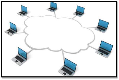
FIG 1.2.1 Cloud Computing Model
Cloud computing is a type of Internet-based computing that provides processing resources and data to computers and other devices on demand. A cloud storage is a type of this cloud providing resources for storage of data. Cloud storage is a cloud computing model where the real data and files can be stored and accessed virtually from anywhere. It is a type of storage method where the raw data is stored in multiple servers of the service provider but for the viewer all the data seems to be appear as if it’s at one place. These storage cloud service providers should keep the server always running and take care of any damage that happens and also protecting from malwares and viruses are the job of the provider. Organization and companies buy such kind of services from cloud service providers for their business purposes. So, by this the organisation can keep their business at all the time and they can be accessible from anywhere. If an organisation wants its own private storage cloud space, the service providers offer them with private cloud where the data resides with them and it’s not anywhere external.
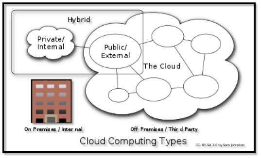
FIG 1.2.2 Cloud Deployment Models
Cloud is basically accessed over internet virtually over a system but this developed environment is an intranet service and accessed like any other website. This cloud is accessed to users only within the organization via local area network. Firstly, users sign up and they get a block of memory available in the storage server. They login and store the files in the block of memory given to them. This storing of files involves a password or a key for cryptographic purposes. Users can share this encrypted files with anyone in the organization.
1.3 Existing System
People communicate through emails, fax and using external storage media, and all this kind of transfer is traditional. Secrets can leak as anyone can see the information. Organizational meetings and communication among people happen through files and documents. There is no secure mechanism to hide the sensitive information.
Disadvantages:
Anyone can go through the information and sensitive data can fall into people with wrong intentions and such loss of secrets can cause problems to the defence of our country. And, the data is sitting there and is not digitalized and any one can go through this unprotected documents.
1.4 Proposed System
Provide a storage cloud platform where the data is stored in the storage cloud. This data is protected with cryptographic algorithms where the user’s data is password protected but just like a password, this application has a key, wherein this key is used in encryption and decryption process. The protected data of one user can be shared with other users and is stored in the cloud safe with end to end protection.
Advantages:
- Accessibility: Users data is always accessible from anywhere of the organisation and is also accessible to others.
- Protected: The user’s information is protected and user is the key to unlock this data. The admin even though has access to the storage server, he cannot read the data.
- Information Security: On transmission of data, security is ensured by firewalls and in addition, double security is ensured by transmitting encrypted data.
- Reliability: The cloud ensures the data to be safely exist in his storage space and ensures no loss of information.
- Usability: The application is accessible over the intranet using a web browser which is a cross platform measure. The application can run on a windows pc as a standalone version.
2. SYSTEM REQUIREMENTS
2.1 Software Requirements:
- .Net Framework version 4.5
- Visual Studio IDE 2015
- C# Programming Language
- Cryptography Libraries
- Web Browser
2.2 Hardware Requirements:
- Storage Server
- Authentication Server
2.3 H/W System Configuration:
- PROCESSOR – Intel (R) Core (TM) i3-4200 (min)
- SPEED – CPU @1.60 GHz 2.30GHz
- RAM – 1GB (min)
- HARD DISK – 128GB (min)
2.4 S/W System Configuration:
- OPERATING SYSTEM: WINDOWS/MAC/Ubuntu
- FRONT END: ASPX/C# Windows Application
3. MODULE DESCRIPTION
Modules of the System
- Cloud Computing
- Architecture of Cloud Computing
- Security Implementations
3.1 Cloud Computing
Cloud Computing is a misnomer. It’s not a cloud but to say it simpler it’s just accessing resources through internet so it’s also called internet computing. Internet is visualized as cloud because it’s like seen from everywhere, so began the journey of cloud. This cloud computing can be used to access many thing over the internet like resources, infrastructure, services, and many operations overs the network to meet the business demand. The cloud service provider just offers what that has been asked and the user uses these services, users doesn’t care about where these resources are until it’s the situation of private cloud. These user’s services are basically used using the virtualization technology.
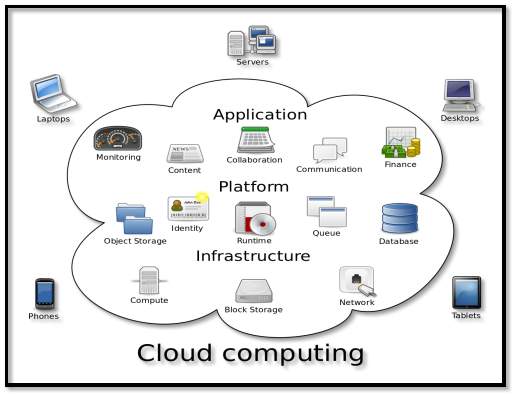
FIG 3.1.1 Cloud Computing
The goal of cloud computing is to allow users to take benefit of their work and use the technologies needed without the worry or knowledge of how resources get scaled and new technological applications are available.
3.2 Architecture of Cloud Computing
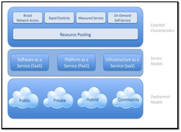
FIG 3.2.1 Cloud Computing Architecture
3.2.1 Cloud Computing Essential Characteristics
3.2.1.1 On-demand self-service: On-demand self-service means that the user has a service provided by the cloud service provider and if the technology needs any additional resources like more storage space and more fast processing, without the users provision the service provider offers the additional resources on demand, automatically. So now the users need not be concerned about the system specification and can do his work, whereas it’s the service provider who does everything. On-demand (OD) computing is popular technology where computing resources automatically scalable. These resources are at the user’s location or at the service provider side.
3.2.1.2 Broad network access: Broad network access refers that the resources or services offered by the cloud service provider are available across many broad devices which are connected to the network. Many devices like mobile phone, tablet, pc, laptop and any device. These cloud resources are accessible from anywhere over the internet. Compute resources forty years ago, were scarce and costly.
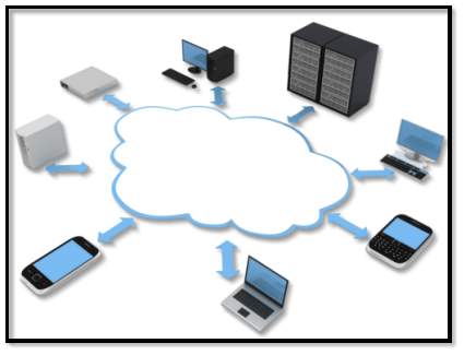
FIG 3.2.1.1 Broad Network Access
3.2.1.3 Resource pooling: Resource pooling is as follows, when a community takes a cloud service and the all use common resources like the data storage. Certain data is public among all the users of a community. In such a case the data should be shared i.e. public. In such scenario, the resource pooling is required. And, when one user of a community is not using resource like temporary memory and another customer needs memory very urgently, so the resource of another user can be used. This is resource pooling. The services can be adjusted to suit each client’s needs without any changes being displayed to the other end user client.
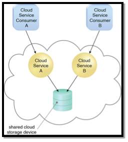
FIG 3.2.1.2 Resource Pooling
3.2.1.4 Rapid elasticity: Rapid elasticity is a very important feature of cloud computing. When a business requests for the cloud service and over the years the company might expand. This leads to more cloud resources request made to the service provider. The storage needs to increase and the physical resources. So, the cloud should be easily evolving without the user knowing. The cloud should be able to scale itself or extend itself so to meet future requirements. This is rapid elasticity.
3.2.1.5 Measured service: Measured service is needed to compute how much of cloud resources are being used by one user. These usages can be bandwidth, physical resources like ram, processors, storage capacity etc. By measuring all these the client pays only for what he uses. This measured service is not just for taxing the user but also to analyze the user’s activity and using these statistics also the scalability depends. The unused resources can be removed from him and use resource pooling concept to use these unused resources for other need. Also, the time can be measured and the location from where the cloud is being accessed can also be noted.
3.2.2 Cloud Computing Service Models
Cloud-computing providers offer the services in three different models. These models are considered as standard by NIST. These models are “Software as a Service(SaaS)”, “Platform as a Service(PaaS)” and “Infrastructure as a Service(IaaS)”. There is another service called a “Mobile Backend as a Service(MBaaS). These models offer different increasing abstraction one after one and each are built on each other. These are explained as follows.
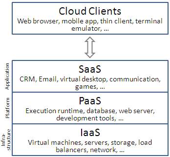
FIG 3.2.2.1 Cloud Computing Model
3.2.2.1 Software as a Service (SaaS): This is a service provided to the customer where the software they demand i.e. applications that the users want to use are provided to them on the cloud infrastructure and this application is used by the customer for his business purposes. As the application is on the cloud the user can access it basically from any device that has internet connection using a web browser. The client does not control or manage the underlying technology like connectivity to servers or application license renewal or the operating system, storage space available. These all underlying backend is taken care by the cloud provider. The user just uses his software.
3.2.2.2 Platform as a Service (PaaS): Here a platform is provided to the user where he can use this provided platform and perform any activity he wants to. For example, let’s just consider a programming platform. User can use any type of programming language and these involve different libraries. May be user can also get external libraries. He might use the test tools like debugger here itself. In this way, entire platform is provided to user. The client does not control or manage the underlying technology like connectivity to servers or application license renewal or the operating system, storage space available. These all underlying backend is taken care by the cloud provider.
3.2.2.3 Infrastructure as a Service (IaaS): The IaaS service is basically giving all the whole infrastructure to the user. This means that the computer is prepackaged and is given to the user and he can do whatever he wants to. He can use all different software’s and install any applications. The whole computer infrastructure is provided to the user and he can choose what OS and what specifications are needed and this whole infrastructure is accessed over the internet. The client does not control or manage the underlying technology like connectivity to servers or application license renewal or the operating system, storage space available. These all underlying backend is taken care by the cloud provider.
3.2.3 Cloud Computing Deployment Models
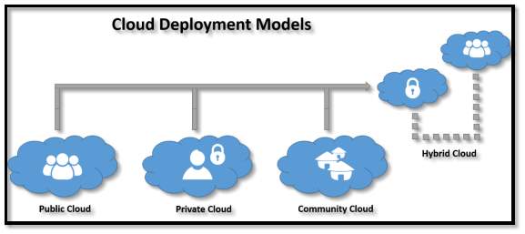
FIG 3.2.2.2 Cloud Computing Model
3.2.3.1 Private Cloud: Private cloud is an infrastructure used for a single organisation. This cloud is managed by the third party and depending on the level of privacy this cloud can be operated internally. A private cloud project requires lot of technology like virtualization to make it accessible to all the people of organisation. This private cloud setup by the organisation also involves lot of planning on the resources that they need and think about future scalability. The private cloud has significant physical footprint, hardware, requiring memory allocation of space and environmental controls. These assets must be refreshed periodically which results in additional capital expenditures.
3.2.3.2 Public Cloud: A public cloud is a type of cloud where the services and offered to the public and is open for them to choose the services they like. These public clouds are basically offered for free. The only difference between the public cloud and private cloud is the accessibility, where all can access public cloud but the private cloud is used by group of people. They both have similar architecture and the difference lies between accessibility. Some examples of public cloud service providers are Amazon Web Services (AWS), Microsoft and Google services where all are accessed via the Internet.
3.2.3.3 Hybrid Cloud: Hybrid cloud is combination of two or more clouds i.e. the combination of private, public and community clouds. The accessibility might be different but the services offered and mostly similar. The hybrid cloud allows users/organisation to extend either the capability and capacity of a cloud service using integration, aggregation and customization with other cloud service. For example, an organization stores sensitive data of an organisation privately at client side on a private cloud application, but can interconnect that application to another business intelligence application provided on a public cloud as a software service.
3.2.3.4 Community Cloud: Community cloud shares cloud infrastructure with other organizations for a specific concern like security, compliance, jurisdiction etc. whether managed by third party or internally by organisation or service provider. Costs are spread in such a way that fewer users than a public cloud and many of private cloud are done, so only some of the investment are realized.
3.3 Security Implementation
3.3.1 Cryptography
Cryptography or cryptology is study of algorithms and techniques for secure transfer or communication of data. More specifically, cryptography deals with construction of algorithms and protocols which can change the data which is being communicated into unreadable format making it impossible to read. Cryptography in modern age was synonymous with encryption, the conversion of data from readable format to unreadable format. But modern cryptography is purely based on mathematical calculations and theories. Cryptography algorithms are designed in such a way that here algorithms are computational hard and unbreakable. Theoretically it’s possible to break it but it’s practically impossible. That’s the reason why these algorithms are computationally secure. During this modern time cryptography is referred as encryption where the readable format called plain text is converted into unreadable format called cipher text. And decryption is reverse of encryption where the unreadable format of text called cipher text is converted into plain text. The generation of cipher text is controlled by the algorithm and a key. This key is secret and based upon this key the cipher text is generated.
3.3.2 Encryption
In cryptography, encryption is the process of encoding the information where the readable parts of communicated message are changed into unreadable content. This encryption process involves the message that is readable which is called plaintext, this plaintext encrypted using an encryption algorithm and a key, generated text that is in unreadable format. This unreadable text is called ciphertext. Key is used in encryption and ciphertext is produced and its practically impossible to decrypt the cipher text without the key to generate the plain text.
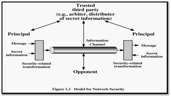
FIG 3.3.1 Network Security Mechanism
3.3.3 Encryption Process
The encryption process of data involves the following steps. First the data passes through the algorithm which is called encryption algorithm and this algorithm consists key. This data called plaintext passes through an encryption algorithm and using a key converts this plaintext into cipher text.
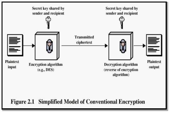
FIG 3.3.2 Model of Encryption
There are two types of encryptions
- Asymmetric Encryption
- Symmetric Encryption
3.3.3.1 Symmetric Key Encryption: Symmetric-key encryption refers encryption technique where both the sender and receiver uses same key which is called public key meaning sender and receiver uses the same key for encryption and decryption for the cryptographic purposes. Most of the symmetric key encryption are implemented as block cipher methods or stream cipher methods. Block cipher method means that A block cipher method involves the plain text divided into many blocks of characters and stream uses a continuous flow of data.
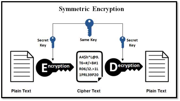
FIG 3.3.3.1 Symmetric Encryption
3.3.3.2 Asymmetric Key Encryption: The symmetric key encryption uses same key for both encryption and decryption and here the private details of the key are being lost confidentiality. And this key might be used for multiple group messages. The problem with symmetric key encryption is that the key management needs to be more secure. So, to make each communicating party use different key such that the decryption process gives the same plain text result.
Diffie Whitfield and Hellman Martin proposed a theory of public key and private key where the cryptography process involves two different mathematically related keys that are a public key for receivers and a private key for the sender. Public key is constructed in such a way that calculation of private key is computationally infeasible from the other public key even though they are related.
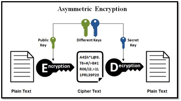
FIG 3.3.3.2 Asymmetric Encryption
In public key encryption algorithm, the public key is freely distributed to the receivers and the sender’s private key remains secret. Here in this cryptography a public key is used for encryption while the private or secret key is used for decryption. Diffie Hellman key exchange protocol is a solution that is widely used in secure communications to allow two parties to secretly agree on a shared encryption key.
3.3.4 Encryption Algorithms
3.3.4.1 Data Encryption Standard: The Data Encryption Standard is a symmetric block cipher developed by IBM and this algorithm uses a 56-bit key for encryption/decryption purpose of 64-bit block of data. Key in DES is a 64-bit key where every 8th bit is ignored which is a parity bit used for calculating errors. However, it is usual to set each 8th bit so that each group of 8 bits has an odd number of bits set to 1. DES is an implementation of a Feistel Cipher and like Feistel it uses 16 round structure.
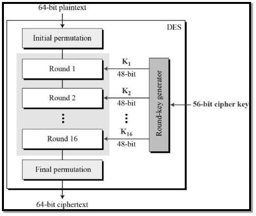
FIG 3.3.4.1 DES Structure
General Structure of DES is shown in the above illustration. Since DES is like Feistel Cipher structure the DES consists following functions
- Round function
- Key schedule
- Any additional processing − Initial and final permutation
Initial and Final Permutation: Initial permutation and final permutations process involves straight Permutation boxes (P-boxes) which are inverses of each other. They involve no cryptographic transformation in DES. The initial and final permutations are shown as follows
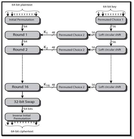
FIG 3.3.4.2 DES Process
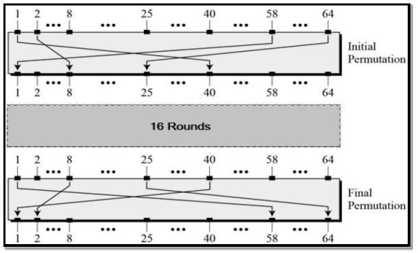
FIG 3.3.4.3 Initial/Final Permutation
Round Function: Round function involves Expansion, XOR and substitution and then involves straight P-box.
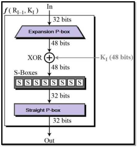
FIG 3.3.4.4 Round Function
Expansion Permutation Box – Expansion process involves 32-bit expanded into 48-bit key value. Permutation logic is shown below –
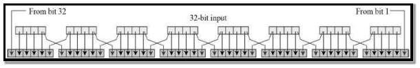
FIG 3.3.4.5 Expansion Permutation Box
The graphically permutation logic is described as table in DES specification illustrated as shown –
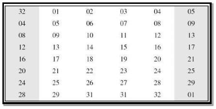
FIG 3.3.4.6 Expansion Box Table
XOR (Whitener) − After the expansion process the 48-bit value is passed through XOR function. The round key is used only in this operation to XOR with.
Substitution Boxes − The Substitution box converts the 48-bit value to 32-bit value to give in input in next round.
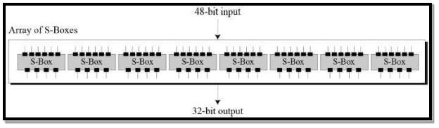
FIG 3.3.4.7 Substitution Box
The S-box rule is illustrated below –
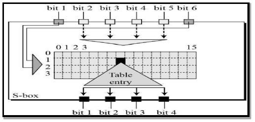
FIG 3.3.4.8 S-Box Rule
Straight Permutation – In ending of the round function the values of the 32 bit are altered using the straight permutation.
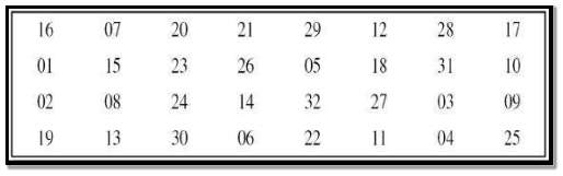
FIG 3.3.4.9 S-Box Straight Permutation
Key Generation: The round key generated sixteen 48 bit keys from 56 bit keys. The process of key generation is as follows –
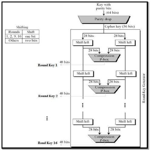
FIG 3.3.4.10 Key Generation
The logic for Parity drop, shifting, and Compression P-box is given in the DES description above.
3.3.4.2 Triple DES: Exhaustive key search against DES in late 1990 caused a problem in secure transfer. The key of DES was becoming east to break down and this lead to worrying cause amongst users of DES. The best logical and pragmatic approach is to not abandon the DES but change how DES operates. This led to the new modified scheme of Triple DES which is also known as 3DES.
Triple DES process basically involves the user to first generate main keys, TDES key K, which consists other three different DES keys K1, K2 and K3. So, the TDES key length is 168 bits The encryption scheme is illustrated as follows –
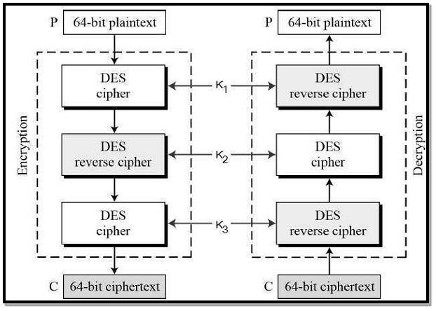
FIG 3.3.4.11 Triple DES
The encryption-decryption process is as follows –
- Encrypt the plaintext block using single DES key K1
- Decrypt output of step 1 using DES key K2
- Finally Encrypt output of step 2 using DES key K3
- The output of step 3 is the ciphertext.
- Decryption of a generated cipher is a reverse process of encryption. First decrypt using key K3, then Encrypt with key K2, and finally Decrypt with key K1.
As Triple DES design as an ENC-DEC-ENC process, it is possible to use a Triple DES method implementation for single DES by setting K1, K2 and K3 all to the same value. By doing this we can provide backwards compatibility with DES. Triple DES systems are significantly more secure than single DESs but doing DES 3*2 times for encryption and decryption is a slower process.
4. SOFTWARE ENVIRONMENT
4.1 .Net Framework version 4.5
.NET Framework could be a computer code framework developed by Microsoft that works totally on Microsoft Windows. it’s an oversized category library referred to as Framework Category Library (FCL) and provides language ability (each language will use code written in different languages) through numerous programming languages. Programs written for the .NET Framework square measure run in an exceedingly computer code atmosphere referred to as the Common Language Runtime (CLR), Associate in Nursing application virtual machine that gives services like security, memory management, and exception handling. FCL and CLR along represent .NET Framework.
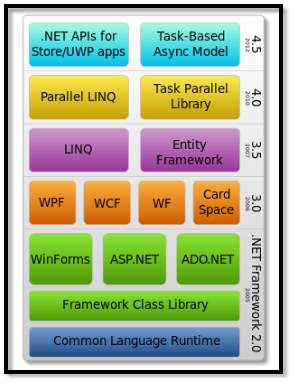
FIG 4.1.1 .Net Framework Architecture
FCL gives UI, information get to, database availability, cryptography, web application improvement, numerical calculations and system interchanges. Developers deliver programming by joining their source code with the .NET Framework and different libraries. The structure is proposed to be utilized by the clear majority of the new applications made for the Windows stage. Microsoft likewise delivers a very incorporated improvement condition for .NET programming called Visual Studio. The .NET Framework begun as exclusive programming, although the organization attempted to institutionalize the product stack very quickly, even before its initially discharge. Regardless of institutionalization endeavors, designers, especially those in open source and open source groups, communicated their worry with the chose terms and points of view of any open source and open source usage, particularly concerning licenses programming. From that point forward, Microsoft has changed the advancement of .NET to more nearly take after a contemporary model of a product extend created by the group, including issuing a refresh of its promising patent to address concerns.
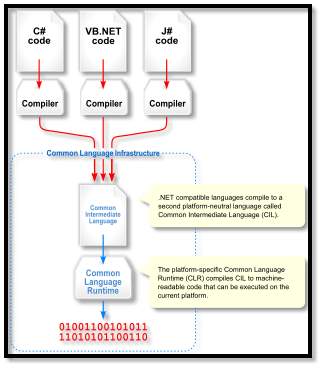
FIG 4.1.2 .Net Framework Working
4.1.1 .NET Architecture
Common Language Infrastructure – Regular Language Infrastructure (CLI) gives a dialect impartial application improvement and usage stage, including special case dealing with, refuse gathering, security and interoperability highlights. By running the centre of .NET Framework inside the extent of CLI, these components are not bound to one dialect, but rather will be accessible in the numerous dialects upheld by the structure. Microsoft’s execution of CLI is Common Language Runtime (CLR). It fills in as the .NET Framework yield motor. Every single .NET program is performed under the supervision of CLR, which ensures many components and practices in memory administration, security and special case taking care of. For PC programs running on CLI, they should be accumulated into Common Intermediate Language (CIL) – instead of incorporated in machine code. In execution, a CIL code is gone into a design system in-time compiler (JIT) in the machine code. Notwithstanding, to enhance execution, will be. NET Framework furnished with Native Image Generator (NGEN), which performs before arrangement.
Assemblies – Incorporated CIL code is put away in CLI congregations. As portrayed in the determination, the arrangements are put away in Portable Executable (PE) record organize, basic on Windows stage for all unique connection libraries (DLL) and executable EXE documents. Every gathering comprises of at least one records, which must contain a show containing the metadata for the get together.
Class Library – .NET Framework incorporates an arrangement of standard class libraries. The class library is composed in a chain of importance of namespaces. The greater part of the implicit application programming interfaces (APIs) are a piece of either System or Microsoft namespaces. These class libraries execute numerous normal capacities, for example, record perusing and composing, realistic rendering, database association, and XML archive control. The class libraries are accessible for all CLI consistent dialects. The class library is partitioned into two sections (with no reasonable limit): Base Class Library (BCL) and Framework Class Library (FCL). BCL incorporates a little subset of the whole class library and is the centre arrangement of classes that fill in as the essential API of CLR. For .NET Framework, most classes considered being a piece of BCL live in mscorlib.dll, System.dll and System.core.dll. FCL is a superset of BCL and alludes to the whole class library that boats with .NET Framework. It incorporates an extended arrangement of libraries, including the Windows Forms, ASP.NET, and Windows Presentation Foundation (WPF) additionally expansions to the base class libraries ADO.NET, Language Integrated Query (LINQ), Windows Communication Foundation (WCF), and Workflow Foundation (WF).
App Models – On the class libraries, numerous application models are utilized to make applications. .NET Framework Bolsters Console, Windows Forms, Windows Presentation Foundation, ASP.NET and ASP.NET Core applications of course. Other application models are offered by option executions of the .NET Framework. Comfort, UWP and ASP.NET Core are accessible on .NET Core.
C++/CLI – Microsoft presented C++/CLI in Visual Studio 2005, which is a dialect and methods for incorporating Visual C++ projects to keep running inside the .NET Framework. A few sections of the C++ program keep running inside an unmanaged Visual C++ Runtime, while uniquely changed parts are converted into CIL code and keep running with the .NET Framework’s CLR.
4.1.2 .Net Framework Design principles
- Interoperability: Since PC frameworks usually require connection amongst more current and more established applications, .NET Framework gives intends to get to capacities actualized in more current and more seasoned projects that execute outside .NET condition. Access to Component Object Model (COM) segments is given in System.Runtime. Interop Services and System.EnterpriseServices namespaces of the structure. Access to different capacities is by means of Platform Invocation Services (P/Invoke). Access to .NET capacities from local applications is by means of invert P/Invoke work.
- Language independence: . NET Framework presents a Common Type System (CTS) that characterizes every single conceivable data sorts and programming develops upheld by CLR and how they might possibly connect with each other fitting in with CLI particular. Due to this component, .NET Framework underpins the trading of sorts and question examples amongst libraries and applications composed utilizing any accommodating .NET dialect.
- Type safety: CTS and the CLR utilized as a part of .NET Framework additionally authorize sort wellbeing. This averts not well characterized throws, wrong strategy summons, and memory estimate issues while getting to a question. This likewise makes most CLI dialects statically wrote (with or without sort deduction). In any case, beginning with .NET Framework 4.0, the Dynamic Language Runtime augmented the CLR, enabling powerfully wrote dialects to be actualized on the CLI.
- Portability: While Microsoft has never executed the full structure on any framework apart from Microsoft Windows, it has built the structure to be cross-stage, and usage are accessible for other working frameworks (see Silverlight and § Alternative usage). Microsoft presented the determinations for CLI (which incorporates the center class libraries, CTS, and CIL), C#, and C++/CLI to both Ecma International (ECMA) and International Organization for Standardization (ISO), making them accessible as official measures.
- Security: NET Framework has its own security instrument with two general components: Code Access Security (CAS), and approval and confirmation. CAS depends on confirmation that is related with a get together. Commonly, the confirmation is the wellspring of the get together (regardless of whether it is introduced on the nearby machine or has been downloaded from the Internet). CAS utilizes proof to decide the consents conceded to the code. Other code can request that calling code be conceded a predetermined consent. The request makes CLR play out a call stack walk: each get together of every strategy in the call stack is checked for the required authorization; if any get together is not conceded the consent a security exemption is tossed.
- Memory management: CLR liberates the designer from the weight of overseeing memory (distributing and authorizing when done); it handles memory administration itself by distinguishing when memory can be securely liberated. Instantiations of .NET sorts (articles) are designated from the overseen pile; a pool of memory overseen by CLR. For whatever length of time that a reference to a protest exists, which might be either immediate, or through a chart of items, the question is thought to be being used. At the point when no reference to a question exists, and it can’t be come to or utilized, it progresses toward becoming waste, qualified for accumulation.
- Performance: At the point when an application is first propelled, the .NET Framework incorporates the CIL code into executable code utilizing it’s without a moment to spare compiler, and stores the executable program into the .NET Native Image Cache. Because of reserving, the application dispatches speedier for consequent dispatches, even though the primary dispatch is normally slower. To accelerate the principal dispatch, engineers may utilize the Native Image Generator utility to physically early gather and store any .NET application.
4.2 C# Programming Language
C# is a current, broadly useful, question situated programming dialect created by Microsoft and endorsed by European Computer Manufacturers Association (ECMA) and International Standards Organization (ISO). C# was created by Anders Hejlsberg and his group amid the improvement of .Net Framework. C# is intended for Common Language Infrastructure (CLI), which comprises of the executable code and runtime condition that permits utilization of different abnormal state dialects on various PC stages and designs. The accompanying reasons make C# a broadly utilized proficient dialect: It is a modern, general-purpose programming language
- Object Oriented.
- Component Oriented.
- Ear to learn.
- Structured language.
- Multi-Platform Compilation
- It is a part of .Net Framework.
- Many Libraries
Strong Programming Features of C# – Even though C# builds nearly take after conventional abnormal state dialects, C and C++ and being a protest arranged programming dialect. It has solid similarity with Java, it has various solid programming highlights that make it charming to various software engineers around the world.
- Boolean Conditions
- Automatic Garbage Collection
- Standard Library
- Assembly Versioning
- Properties and Events
- Delegates and Events Management
- Easy-to-use Generics
- Indexers
- Conditional Compilation
- Simple Multithreading
- LINQ and Lambda Expressions
- Integration with Windows
5. CODING AND TESTING
5.1 Login.aspx.cs
using System;
using System.Collections.Generic;
using System.Linq;
using System.Web;
using System.Web.UI;
using System.Web.UI.WebControls;
using System.Data.SqlClient;
using System.Data;
public partial class Login : System.Web.UI.Page
{
// dbconncetion dc = new dbconncetion();
public string name, position, division, pwd;
public string dlrlid;
protected void Page_Load(object sender, EventArgs e)
{
}
protected void btnLogin_Click(object sender, EventArgs e)
{
if (txtUserName.Text == “admin” && txtPassword.Text == “admin”)
{
Session[“name”] = txtUserName.Text;
Response.Redirect(“Cloud.aspx”);
}
else
{
lblloginmsg.Text = “Enter valid credentials..!!”;
lblloginmsg.ForeColor = System.Drawing.Color.DarkRed;
}
//try
//{
// if (txtUserName.Text == “admin” && txtPassword.Text == “admin” && ddlType.SelectedItem.Text == “Audit”)
// Response.Redirect(“Home.aspx”);
// string userid = txtUserName.Text;
// DataSet ds = dc.getDetails(userid);
// if (ds.Tables[0].Rows.Count > 0)
// {
// name = ds.Tables[0].Rows[0][“Name”].ToString();
// Session[“Name”] = name;
// position = ds.Tables[0].Rows[0][“Position”].ToString();
// Session[“Position”] = position;
// division = ds.Tables[0].Rows[0][“Division”].ToString();
// Session[“Division”] = division;
// dlrlid = (ds.Tables[0].Rows[0][“Dlrl_id”].ToString());
// Session[“DLRL_ID”] = dlrlid;
// pwd = ds.Tables[0].Rows[0][“AuditPwd”].ToString();
// }
// if (txtUserName.Text != “” && txtPassword.Text != “” && ddlType.SelectedItem.Text != “–Select–“)
// {
// if ((txtUserName.Text == dlrlid) && ddlType.SelectedItem.Text != “–Select–“)
// {
// if (txtUserName.Text == dlrlid && txtPassword.Text == pwd && ddlType.SelectedItem.Text == “Division” && (position == “Division Head” || position == “Group Director”))
// {
// Response.Redirect(“Home.aspx”);
// }
// else if (txtUserName.Text == dlrlid && txtPassword.Text == pwd && ddlType.SelectedItem.Text == “IndentOffcr” && (position == “” || position == null))
// {
// Response.Redirect(“Home.aspx”);
// }
// else
// {
// lblloginmsg.Text = “Invalid Username and Password..”;
// lblloginmsg.ForeColor = System.Drawing.Color.DarkRed;
// }
// }
// }
// else
// {
// lblloginmsg.Text = “Enter valid credentials..!!”;
// lblloginmsg.ForeColor = System.Drawing.Color.DarkRed;
// }
//}
//catch (Exception ex)
//{
// lblloginmsg.Text = “**Enter valid credentials..!!”;
// lblloginmsg.ForeColor = System.Drawing.Color.DarkRed;
//}
}
}
5.2 Cloud.aspx.cs
using System.Web.UI.WebControls;
using System;
using System.Collections.Generic;
using System.Threading;
using System.Web;
using System.Web.UI;
using System.Security.Cryptography;
using System.IO;
using System.Text;
using System.Data;
using System.Web.UI.HtmlControls;
public partial class Cloud : System.Web.UI.Page
{
public string selectFile = null;
public static string rName, wName, rPath, wPath, tbt, down, directory, name, serverPath, tbt4;
protected void Page_Load(object sender, EventArgs e)
{
DisableDES();
//Panel1.Enabled = false;
//Panel2.Enabled = false;
DisableTDES();
if (Session[“Name”] != null)
name = Session[“Name”].ToString();
serverPath = Server.MapPath(“~/Files/”);
CheckSource(name);
directory = name;
}
protected void CheckSource(string folder)
{
string path = Server.MapPath(“~/Files/”);
DirectoryInfo dir = new DirectoryInfo(path);
foreach (DirectoryInfo d in dir.GetDirectories())
{
if (d.Name == folder)
{
return;
}
}
DirectoryInfo newD = new DirectoryInfo(path + folder);
newD.Create();
}
public void EnableControls()
{
textBox1.Enabled = true;
//button1.Enabled = true;
label1.Enabled = true;
groupBox1.Enabled = true;
rName = null;
tbt = null;
rPath = null;
wName = null;
wPath = null;
down = null;
}
private void DisableControls()
{
textBox1.Enabled = false;
//button1.Enabled = false;
label1.Enabled = false;
}
protected void DisableDES()
{
label2.Enabled = false;
label3.Enabled = false;
label4.Enabled = false;
textBox2.Enabled = false;
button2.Enabled = false;
button3.Enabled = false;
}
protected void DisableTDES()
{
label10.Enabled = false;
label11.Enabled = false;
label12.Enabled = false;
label13.Enabled = false;
textBox8.Enabled = false;
textBox9.Enabled = false;
button10.Enabled = false;
button11.Enabled = false;
}
protected void EnableDES()
{
label2.Enabled = true;
label3.Enabled = true;
label4.Enabled = true;
textBox2.Enabled = true;
button2.Enabled = true;
button3.Enabled = true;
}
protected void EnableTDES()
{
label10.Enabled = true;
label11.Enabled = true;
label12.Enabled = true;
label13.Enabled = true;
textBox8.Enabled = true;
textBox9.Enabled = true;
button10.Enabled = true;
button11.Enabled = true;
}
protected void openFile()
{
selectFile = FileUpload1.PostedFile.FileName;
FileUpload1.PostedFile.SaveAs(Server.MapPath(“~/Uploads/” + selectFile));
}
protected void openFile2()
{
selectFile = FileUpload2.PostedFile.FileName;
FileUpload2.PostedFile.SaveAs(Server.MapPath(“~/Uploads/” + selectFile));
}
protected void DeleteFiles(String s)
{
DirectoryInfo dir = new DirectoryInfo(s);
foreach (FileInfo file in dir.GetFiles())
{
file.Delete();
}
}
protected void button11_Click(object sender, EventArgs e)
{
if (textBox8.Text.Length == 8 && textBox9.Text.Length == 8)
{
down = “TDES-” + wName;
tbt = wPath + @”TDES-” + wName;
TEncDec encryptor = new TEncDec(textBox8.Text.ToString(), textBox9.Text.ToString());
FileStream fread = new FileStream(rPath, FileMode.Open, FileAccess.Read);
FileStream fwrite = new FileStream(tbt, FileMode.Create, FileAccess.Write);
byte[] plain = new byte[fread.Length];
fread.Read(plain, 0, plain.Length);
byte[] cipher = encryptor.Encrypt(plain);
fwrite.Write(cipher, 0, cipher.Length);
fread.Close();
fwrite.Close();
DeleteFiles(Server.MapPath(“~/Uploads/”));
//Page.ClientScript.RegisterStartupScript(this.GetType(), “OpenWindow”, “window.open(‘download.aspx’,’_newtab’);”, true);
button10_Click(sender, e);
}
else
{
ClientScript.RegisterStartupScript(this.GetType(), “Key Error”, “alert(‘Key length not 8 charecters’)”, true);
//MessageBox.Show(“Key length not 8 charecters”, “Key Error”);
}
}
protected void button10_Click(object sender, EventArgs e)
{
radioButton2.Checked = false;
DisableTDES();
label12.Text = “”;
textBox8.Text = “”;
textBox9.Text = “”;
textBox1.Text = “”;
tbt = “”;
textBox1.Enabled = true;
EnableControls();
return;
}
protected void button7_Click(object sender, EventArgs e)
{
Thread openDialog = new Thread(openFile2);
openDialog.SetApartmentState(ApartmentState.STA);
openDialog.Start();
openDialog.Join();
if (selectFile != null)
{
tbt4 = Server.MapPath(“~/Uploads/” + selectFile);
selectFile = null;
}
openDialog.Abort();
if (textBox6.Text.Length >= 8)
{
string dWName, dWPath;
string[] parts = tbt4.Split(‘\’);
//DES-ENCRYPTED-DOCX-name.txt
string[] type = parts[parts.Length – 1].Split(‘-‘);
dWName = type[3].Replace(“.txt”, “.” + type[2].ToLower());
String tct;
tct = Server.MapPath(“~/Files/” + directory + “/”);
dWPath = tct + dWName;
FileStream fread = new FileStream(tbt4, FileMode.Open, FileAccess.Read);
FileStream fwrite = new FileStream(dWPath, FileMode.Create, FileAccess.Write);
byte[] cipher = new byte[fread.Length];
fread.Read(cipher, 0, cipher.Length);
byte[] plain;
if (type[0].Equals(“DES”))
{
EncDec decryptor = new EncDec(textBox6.Text.ToString());
plain = decryptor.Decrypt(cipher);
fwrite.Write(plain, 0, plain.Length);
}
else if (type[0].Equals(“TDES”))
{
TEncDec decryptor = new TEncDec(textBox6.Text, textBox3.Text);
plain = decryptor.Decrypt(cipher);
fwrite.Write(plain, 0, plain.Length);
}
fread.Close();
fwrite.Close();
//Page.ClientScript.RegisterStartupScript(this.GetType(), “OpenWindow”, “window.open(‘download.aspx’,’_newtab’);”, true);
button8_Click(sender, e);
DeleteFiles(Server.MapPath(“~/Uploads/”));
}
}
protected void button8_Click(object sender, EventArgs e)
{
tbt4 = “”;
textBox6.Text = “”;
textBox3.Text = “”;
}
protected void button3_Click(object sender, EventArgs e)
{
radioButton1.Checked = false;
DisableDES();
//Panel1.Enabled = false;
label3.Text = “”;
textBox2.Text = “”;
textBox1.Text = “”;
tbt = “”;
EnableControls();
return;
}
protected void button2_Click(object sender, EventArgs e)
{
if (textBox2.Text.Length == 8)
{
down = “DES-” + wName;
tbt = wPath + @”DES-” + wName;
EncDec encryptor = new EncDec(textBox2.Text.ToString());
FileStream fread = new FileStream(rPath, FileMode.Open, FileAccess.Read);
FileStream fwrite = new FileStream(tbt, FileMode.Create, FileAccess.Write);
byte[] plain = new byte[fread.Length];
fread.Read(plain, 0, plain.Length);
byte[] cipher = encryptor.Encrypt(plain);
fwrite.Write(cipher, 0, cipher.Length);
fread.Close();
fwrite.Close();
//MessageBox.Show(“File ” + wName + “Envrypted Click Download to save file.”);
//Page.ClientScript.RegisterStartupScript(this.GetType(), “OpenWindow”, “window.open(‘download.aspx’,’_newtab’);”, true);
button3_Click(sender, e);
DeleteFiles(Server.MapPath(“~/Uploads/”));
}
else
{
ClientScript.RegisterStartupScript(this.GetType(), “Key Error”, “alert(‘Key length not 8 charecters’)”, true);
//MessageBox.Show(“Key length not 8 charecters”, “Key Error”);
}
}
protected void setPath()
{
Thread openDialog = new Thread(openFile);
openDialog.SetApartmentState(ApartmentState.STA);
openDialog.Start();
openDialog.Join();
if (selectFile != null)
{
textBox1.Text = Server.MapPath(“~/Uploads/”+selectFile);
selectFile = null;
}
openDialog.Abort();
textBox1.Enabled = false;
rPath = textBox1.Text;
string[] pathBreak = rPath.Split(‘\’);
rName = pathBreak[pathBreak.Length – 1];
string[] rBreak = rName.Split(‘.’);
wName = “ENCRYPTED-” + rBreak[1].ToUpper() + “-” + rBreak[0] + “.txt”;
textBox1.Text = rPath;
wPath = Server.MapPath(“~/Files/” + directory + “/”);
//DeleteFiles(wPath);
}
protected void radioButton1_CheckedChanged(object sender, EventArgs e)
{
if (FileUpload1.HasFile)
{
setPath();
if (radioButton1.Checked == true)
{
label12.Text = “”;
EnableDES();
//Panel1.Enabled = true;
DisableControls();
label3.Text = rName;
}
}
else
{
ClientScript.RegisterStartupScript(this.GetType(), “File Error”, “alert(‘Select file to encrypt’)”, true);
radioButton1.Checked = false;
}
}
protected void radioButton2_CheckedChanged(object sender, EventArgs e)
{
if (FileUpload1.HasFile)
{
setPath();
if (radioButton2.Checked == true)
{
label3.Text = “”;
EnableTDES();
//Panel2.Enabled = true;
DisableControls();
label12.Text = rName;
}
}
else
{
ClientScript.RegisterStartupScript(this.GetType(), “File Error”, “alert(‘Select file to encrypt’)”, true);
radioButton2.Checked = false;
}
}
public class EncDec
{
DESCryptoServiceProvider d;
byte[] key;
byte[] iv;
public EncDec(string k)
{
d = new DESCryptoServiceProvider();
key = Encoding.ASCII.GetBytes(k);
iv = Encoding.ASCII.GetBytes(k);
d.Key = key;
d.IV = iv;
}
public byte[] Encrypt(byte[] s)
{
byte[] cipher;
ICryptoTransform i = d.CreateEncryptor();
cipher = i.TransformFinalBlock(s, 0, s.Length);
return cipher;
}
public byte[] Decrypt(byte[] s)
{
byte[] plain;
ICryptoTransform i = d.CreateDecryptor();
plain = i.TransformFinalBlock(s, 0, s.Length);
return plain;
}
}
public class TEncDec
{
TripleDESCryptoServiceProvider d;
byte[] key;
byte[] iv;
public TEncDec(string k1, string k2)
{
string k = k1 + k2;
d = new TripleDESCryptoServiceProvider();
//key1 = Encoding.ASCII.GetBytes(k1);
//key2 = Encoding.ASCII.GetBytes(k2);
key = Encoding.ASCII.GetBytes(k);
iv = Encoding.ASCII.GetBytes(k1);
d.Key = key;
d.IV = iv;
}
public byte[] Encrypt(byte[] s)
{
byte[] cipher;
ICryptoTransform i = d.CreateEncryptor();
cipher = i.TransformFinalBlock(s, 0, s.Length);
return cipher;
}
public byte[] Decrypt(byte[] s)
{
byte[] plain;
ICryptoTransform i = d.CreateDecryptor();
plain = i.TransformFinalBlock(s, 0, s.Length);
return plain;
}
}
}
5.3 Archive.aspx.cs
using System;
using System.Collections.Generic;
using System.Data;
using System.IO;
using System.Linq;
using System.Web;
using System.Web.UI;
using System.Web.UI.WebControls;
public partial class Archive : System.Web.UI.Page
{
public static string name,serverPath,directory;
protected void Page_Load(object sender, EventArgs e)
{
if (Session[“name”] != null)
name = Session[“name”].ToString();
serverPath = Server.MapPath(“~/Files/”);
directory = name;
DisplayFiles(name);
}
protected void DisplayFiles(string folder)
{
List
DirectoryInfo dir = new DirectoryInfo(serverPath + directory + “/”);
foreach (FileInfo f in dir.GetFiles())
{
fNames.Add(f.Name);
}
DataTable dt = new DataTable();
dt.Columns.Add(“Filename”, typeof(string));
dt.Columns.Add(“Download”, typeof(string));
foreach (string s in fNames)
{
AddNewRow(dt, s);
}
dt.AcceptChanges();
GridView1.DataSource = dt;
GridView1.DataBind();
}
protected void AddNewRow(DataTable d, String fName)
{
DataRow row = d.NewRow();
row[“Filename”] = fName;
//get url from GetURL method
string link = GetURL(fName);
row[“Download”] = HttpUtility.HtmlDecode(link);
d.Rows.Add(row);
}
protected string GetURL(string fName)
{
return “” + “download” + “”;
}
protected void GridView1_OnRowCommand(object sender, GridViewCommandEventArgs e)
{
try
{
GridView gv = (GridView)sender;
Int32 RowIndex = Convert.ToInt32(e.CommandArgument.ToString());
GridViewRow currentrow = gv.Rows[RowIndex];
if (e.CommandName == “Page”)
return;
if (e.CommandName == “Delete”)
{
string fname = currentrow.Cells[0].Text;
DirectoryInfo dir = new DirectoryInfo(serverPath + directory + “/”);
foreach (FileInfo f in dir.GetFiles())
{
if (f.Name == fname)
{
f.Delete();
break;
}
}
DisplayFiles(name);
}
}
catch (Exception ex)
{
}
}
protected void GridView1_RowDeleting(object sender, GridViewDeleteEventArgs e)
{
}
}
5.4 Download.aspx.cs
using System;
using System.Collections.Generic;
using System.IO;
using System.Linq;
using System.Web;
using System.Web.UI;
using System.Web.UI.WebControls;
public partial class download : System.Web.UI.Page
{
protected void Page_Load(object sender, EventArgs e)
{
string fName = Request.QueryString[“file”];
string name = Session[“name”].ToString();
string spath = Server.MapPath(“~/Files/” + name + “/”);
DirectoryInfo dir = new DirectoryInfo(spath);
foreach (FileInfo file in dir.GetFiles())
{
if (file.Name == fName)
{
Response.Clear();
Response.ClearHeaders();
Response.ClearContent();
Response.AddHeader(“Content-Disposition”, “attachment; filename=” + file.Name);
Response.AddHeader(“Content-Length”, file.Length.ToString());
Response.ContentType = “text/plain”;
Response.Flush();
Response.TransmitFile(file.FullName);
Response.End();
}
}
}
}
5.5 SYSTEM TESTING
The reason for testing is to find blunders. Testing is the way toward attempting to find each possible blame or shortcoming in a work item. It gives an approach to check the usefulness of segments, sub-gatherings, congregations as well as a completed item It is the way toward practicing programming with the plan of guaranteeing that the Software framework lives up to its necessities and client desires and does not bomb in an inadmissible way. There are different sorts of test. Each test sort addresses a testing necessity.
5.5.1 TYPES OF TESTS
1. Unit testing
Unit testing includes the plan of experiments that approve that the interior program rationale is working appropriately, and that program inputs deliver legitimate yields. All choice branches and inward code stream ought to be approved. It is the trying of individual programming units of the application .it is done after the finish of an individual unit before coordination. This is an auxiliary testing, that depends on learning of its development and is intrusive. Unit tests perform essential tests at segment level and test a business process, application, or potentially framework setup. Unit tests guarantee that every interesting way of a business procedure performs precisely to the recorded determinations and contains obviously characterized inputs and expected outcomes.
2. Integration testing
Combination tests are intended to test coordinated programming segments to decide whether they really keep running as one program. Testing is occasion driven and is more worried with the essential result of screens or fields. Joining tests exhibit that although the parts were independently fulfillment, as appeared by effectively unit testing, the mix of segments is right and predictable. Coordination testing is particularly gone for uncovering the issues that emerge from the mix of segments.
3. Functional test
Functional tests provide systematic demonstrations that functions tested are available as specified by the business and technical requirements, system documentation, and user manuals.
Functional testing is centered on the following items:
- Valid Input : identified classes of valid input must be accepted.
- Invalid Input : identified classes of invalid input must be rejected.
- Functions : identified functions must be exercised.
- Output : identified classes of application outputs must be exercised.
- Systems/Procedures: interfacing systems or procedures must be invoked.
Organization and preparation of functional tests is focused on requirements, key functions, or special test cases. In addition, systematic coverage pertaining to identify Business process flows; data fields, predefined processes, and successive processes must be considered for testing. Before functional testing is complete, additional tests are identified and the effective value of current tests is determined.
4. System Test
System testing ensures that the entire integrated software system meets requirements. It tests a configuration to ensure known and predictable results. An example of system testing is the configuration oriented system integration test. System testing is based on process descriptions and flows, emphasizing pre-driven process links and integration points.
5. White Box Testing
White Box Testing is a testing in which in which the software tester has knowledge of the inner workings, structure and language of the software, or at least its purpose. It is purpose. It is used to test areas that cannot be reached from a black box level.
6. Black Box Testing
Black Box Testing is testing the software without any knowledge of the inner workings, structure or language of the module being tested. Black box tests, as most other kinds of tests, must be written from a definitive source document, such as specification or requirements document, such as specification or requirements document. It is a testing in which the software under test is treated, as a black box. you cannot “see” into it. The test provides inputs and responds to outputs without considering how the software works.
5.5.2 Unit Testing
Unit testing is usually conducted as part of a combined code and unit test phase of the software lifecycle, although it is not uncommon for coding and unit testing to be conducted as two distinct phases. Test strategy and approach: Field testing will be performed manually and functional tests will be written in detail.
Test objectives
- All file uploads must work properly.
- Key should not be simple.
- File access should be consistent.
Features to be tested
- Verify that file extensions are valid and present.
- No duplicate entries of files should be allowed.
- Large file upload should not crash.
5.5.3 Integration Testing
Software integration testing is the incremental integration testing of two or more integrated software components on a single platform to produce failures caused by interface defects. The task of the integration test is to check that components or software applications, e.g. components in a software system or – one step up – software applications at the company level – interact without error.
Test Results: All the test cases mentioned above passed successfully. No defects encountered.
5.5.4 Acceptance Testing
User Acceptance Testing is a critical phase of any project and requires significant participation by the end user. It also ensures that the system meets the functional requirements.
Test Results: All the test cases mentioned above passed successfully. No defects encountered.
6. SYSTEM DESIGN
6.1 INPUT DESIGN
The input design is the link between the information system and the user. It includes the development specification and data preparation procedures and steps required to enable transaction data in a useful form for processing can be achieved by inspecting the computer to read or read data from a written or printed document to test the data directly in the system. The design of the input focuses on controlling the required input, checking the errors, preventing delay, preventing extra steps and keeping the process simple. The input is designed to provide security and ease of use while maintaining privacy. Input Design considered the following:
- What data is to be given in as input?
- How this data has to be arranged or coded?
- The dialog to guide the user while in providing input.
- Methods for validating input and what to do when errors occur.
OBJECTIVES
1. Input Design is the way to changing customizable images of the contribution to a PC-based framework. This description is essential to keep away from errors in the information entry process and to prove the right to the administration to get the right data from the electronic framework.
2. It is achieved by easily understanding the scenes for passing through information to deal with large amounts of information. The purpose of describing information is to make the information section simpler and free from blunders. The information section screen is planned so that each of the information controls can be performed. It also provides record offices.
3. When the information is entered, it checks for its legitimacy. Information can be entered using screens. Appropriate messages are given as necessary, so the customer will not be in corn. Consequently, the purpose of the information configuration is to design an information that is something other than difficult to check.
6.2 OUTPUT DESIGN
A quality output is one that meets the requirements of the end user and clearly displays the information. In each system, the results of the processing are sent to the users and to another system via the output. The export design determines how the information needs to be moved for the immediate need and the export of the copy. It is the most important and direct source information for the user. Efficient and intelligent output design improves the relationship of the system to help user decisions.
1. The design of computer output must be carried out in an organized, thoughtful manner; The correct output must be developed while ensuring that each output element is designed so that people can find the system can use simple and effective. When designing the computer output, they must identify the specific output needed to meet the requirements.
2. Select methods for presenting information.
3. Create document, report, or other formats that contain information produced by the system.
The output form of an information system should accomplish one or more of the following objectives.
- Convey information about past activities, status or projections of the
- Future.
- Signal important events, opportunities, problems, or warnings.
- Trigger an action.
- Confirm an action.
6.3 System Architecture
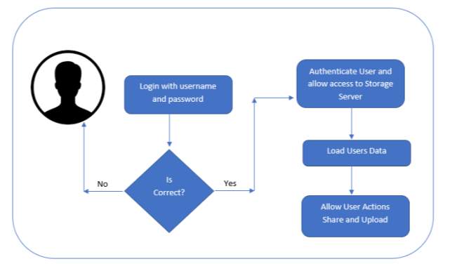
FIG 6.3.1 System Architecture
6.4 UML Concepts
The Unified Modelling Language (UML) is a standard language for writing software blue prints. The UML is a language for
- Visualizing
- Specifying
- Constructing
- Documenting the artefacts of a software intensive system.
The UML is a language which provides vocabulary and the rules for combining words in that vocabulary for communication. A modelling language is a language whose vocabulary and the rules focus on the conceptual and physical representation of a system. Modelling yields an understanding of a system.
6.4.1 Building Blocks of the UML
The vocabulary of the UML encompasses three kinds of building blocks:
- Things
- Relationships
- Diagrams
Things are the abstractions that are first-class citizens in a model; relationships tie these things together; diagrams group interesting collections of things.
1. Things in the UML
There are four kinds of things in the UML:
- Structural things
- Behavioral things
- Grouping things
- A notational thing
Structural things are the nouns of UML models. The structural things used in the project design are:
First, a class is a description of a set of objects that share the same attributes, operations, relationships and semantics.
| Window |
| Origin
Size |
| open()
close() move() display() |
FIG 6.4.1 Class
Second, a use case is a description of set of sequence of actions that a system performs that yields an observable result of value to particular actor.
FIG 6.4.2 Use Case
Third, a node is a physical element that exists at runtime and represents a computational resource, generally having at least some memory and often processing capability.
FIG 6.4.3 Node
Behavioral things are the dynamic parts of UML models. The behavioral thing used is:
Interaction:
An interaction is a behavior that comprises a set of messages exchanged among a set of objects within a context to accomplish a specific purpose. An interaction involves several other elements, including messages, action sequences (the behavior invoked by a message, and links (the connection between objects).
FIG 6.4.4 Message
2. Relationships in the UML:
There are four kinds of relationships in the UML:
- Dependency
- Association
- Generalization
- Realization
A dependency is a semantic relationship between two things in which a change to one thing may affect the semantics of the other thing (the dependent thing).
FIG 6.4.5 Dependency
An association is a structural relationship that describes a set links, a link being a connection among objects. Aggregation is a special kind of association, representing a structural relationship between a whole and its parts.
FIG 6.4.6 Association
A generalization is a specialization/ generalization relationship in which objects of the specialized element (the child) are substitutable for objects of the generalized element (the parent).
FIG 6.4.7 Generalization
A realization is a semantic relationship between classifiers, where in one classifier specifies a contract that another classifier guarantees to carry out.
FIG 6.4.8 Realization
6.4.2 UML Diagrams
1. Use Case Diagram
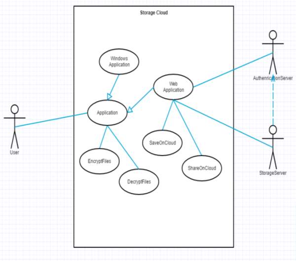
FIG 6.4.9 Use case Diagram
The above diagram is Use Case diagram of our system. It shows the set of actions performed by various users. In our system, we have 3 types of users. They are 1) User 2) Authentication Server and 3) Storage Server. As described earlier, the content in the Ovals are actions performed in the system and those actors are like symbols represent users in system. Those dashed lines from user to action means users are performing those actions respectively.
2. Class Diagram
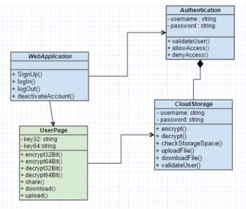
FIG 6.4.10 Class Diagram
The above diagram represents class diagram of our system i.e., it shows various classes used in our system and the relationship with one class to other in the system. Each rectangle box represents a class and the upper portion of it represents class name and middle portion represents attributes of the class and the lower represents the functions performed by that class.
3. Activity Diagram
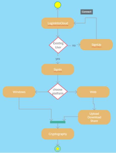
FIG 6.4.11 Activity Diagram
The above diagram represents activity diagram of the system i.e., it represents the flow of activities in our project. Dot at the start represents starting and dot with circle represents ending and an activity is represented as curve sided rectangle. On seeing it we can understand the flow activities that must be gone from start to end.
4. Sequence Diagram
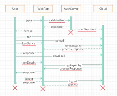
FIG 6.4.12 Sequence Diagram
The above diagram Show sequence diagram for a registered user. It represents sequence or flow of messages in system among various objects of the system in user’s life time. The rectangle boxes at top represent objects that are actors and the dashed lines dropping from those boxes are life lines which shows existence of the object up to what time. The boxes on the dashed lines are events and the lines connecting them represent messages and their flow.
5. Collaboration Diagram
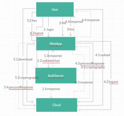
FIG 6.4.13 Collaboration Diagram
The above diagram Show collaboration diagram for a user. It represents sequence or flow of messages among system of various objects and their relationship throughout the life time. The rectangle boxes represent objects that are actors and the dashed lines dropping from those boxes are dependencies which shows dependence of one object with other. The boxes on the dashed lines are events and the lines connecting them represent messages and their flow.
6. Component Diagram
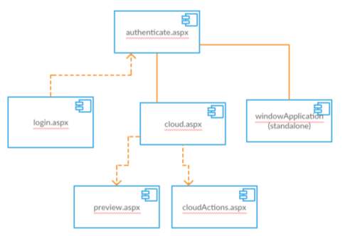
FIG 6.4.14 Component Diagram
A component diagram shows various components invoked in system at time of execution of various functions in the system.
8. Deployment Diagram
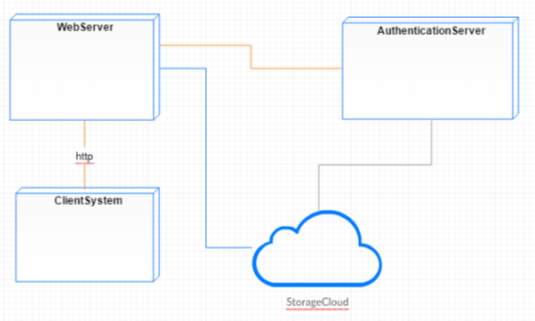
FIG 6.4.15 Deployment Diagram
The above diagram represents deployment diagram of the system i.e., it represents the structure diagram which shows architecture of the system as deployment (distribution) of software artifacts to deployment targets. Artifacts represent concrete elements in the physical world that are the result of a development process.
7. RESULTS AND ANALYSIS
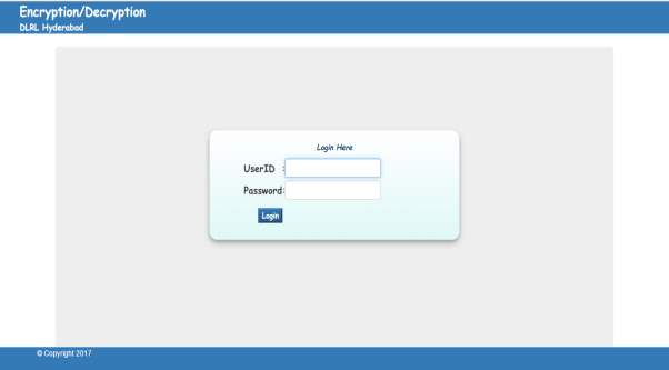
FIG 7.1 Cloud Login Screen
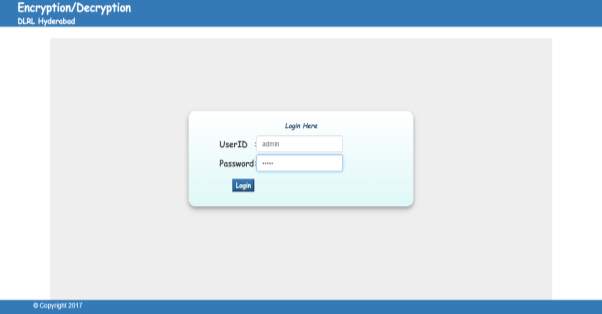
FIG 7.2 Login Screen with Credentials
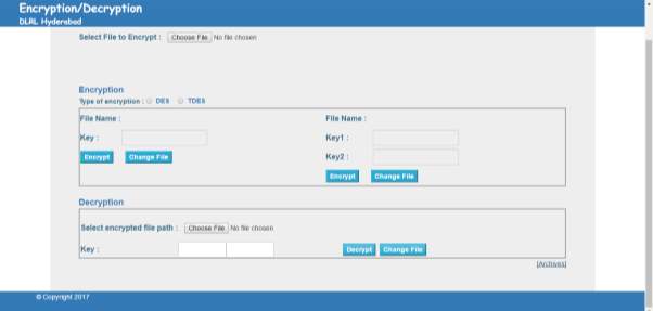
FIG 7.3 User Activity Page
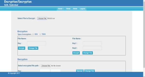
FIG 7.4 User File Upload Page
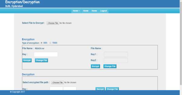
FIG 7.5 DES Encryption
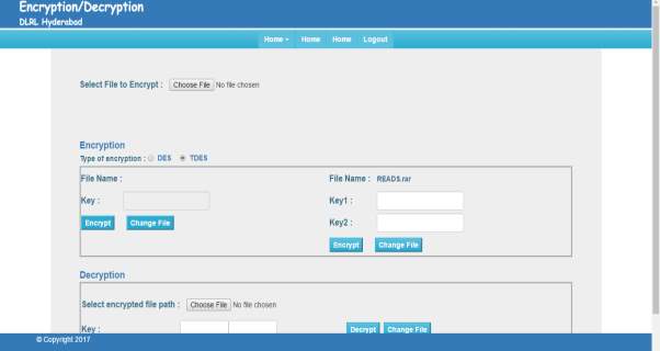
FIG 7.6 TDES Encryption
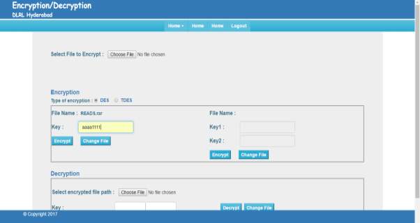
FIG 7.7 DES Key
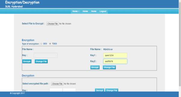
FIG 7.8 TDES Key
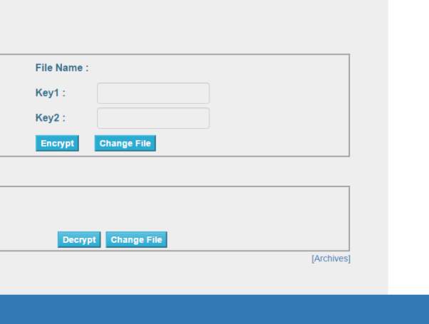
FIG 7.9 Archives Link
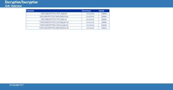
FIG 7.10 Archives Page
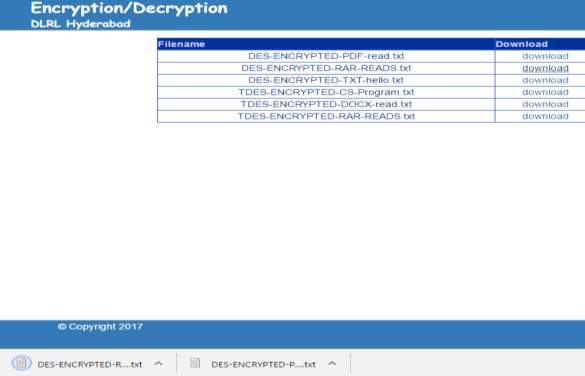
FIG 7.11 Archives DES Download 1
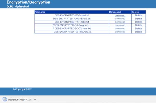
FIG 7.12 Archives DES Download 2

FIG 7.13 Downloaded File
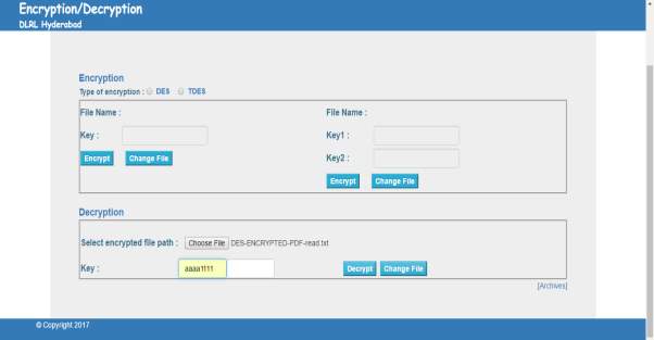
FIG 7.14 Decryption DES
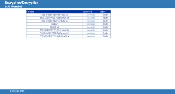
FIG 7.15 DES Decrypted File Archives
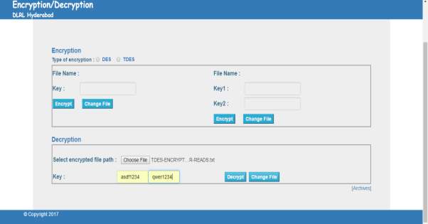
FIG 7.16 Decryption TDES
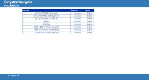
FIG 7.17 TDES Decrypted File Archives
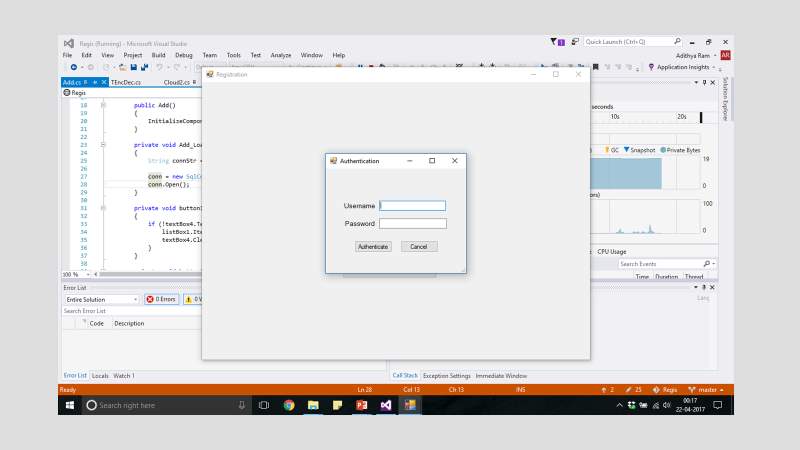
FIG 7.18 Windows Application Authentication
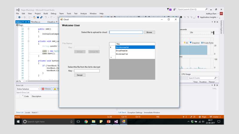
FIG 7.19 Windows File Upload
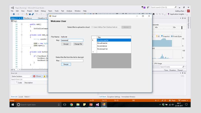
FIG 7.20 Windows Encryption Key
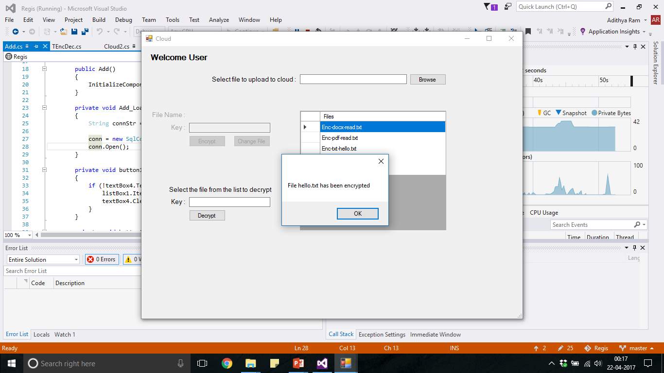
FIG 7.21 Windows Encryption List
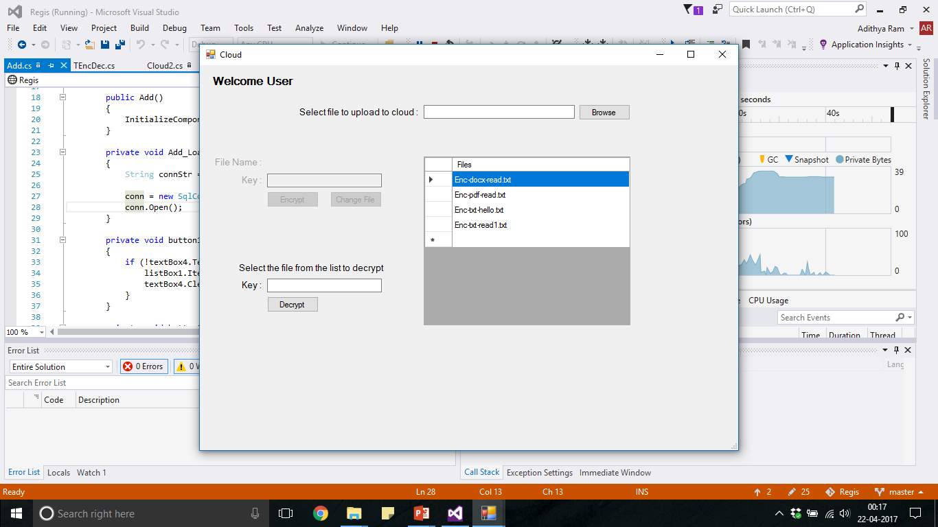
FIG 7.22 Windows Decryption Item Select
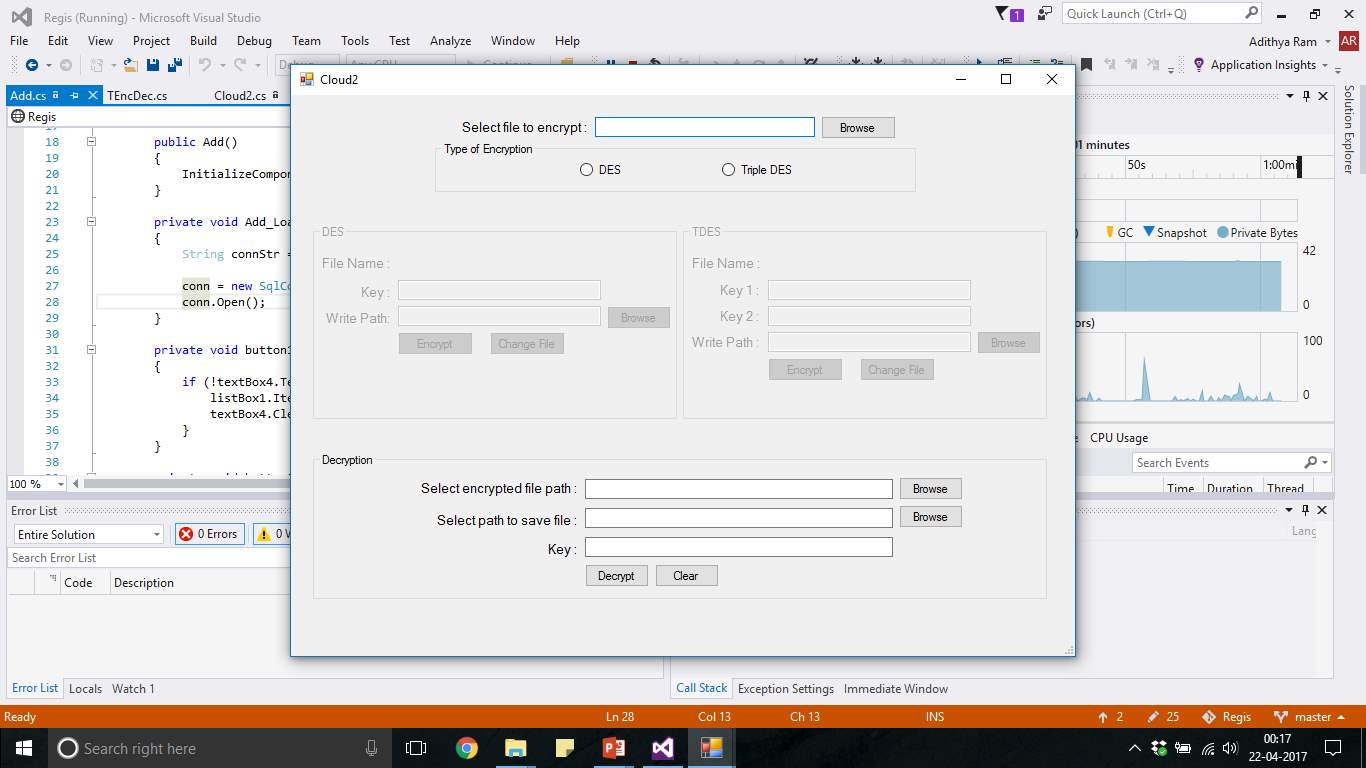
FIG 7.23 Windows 2 Application ENC/DEC File Upload
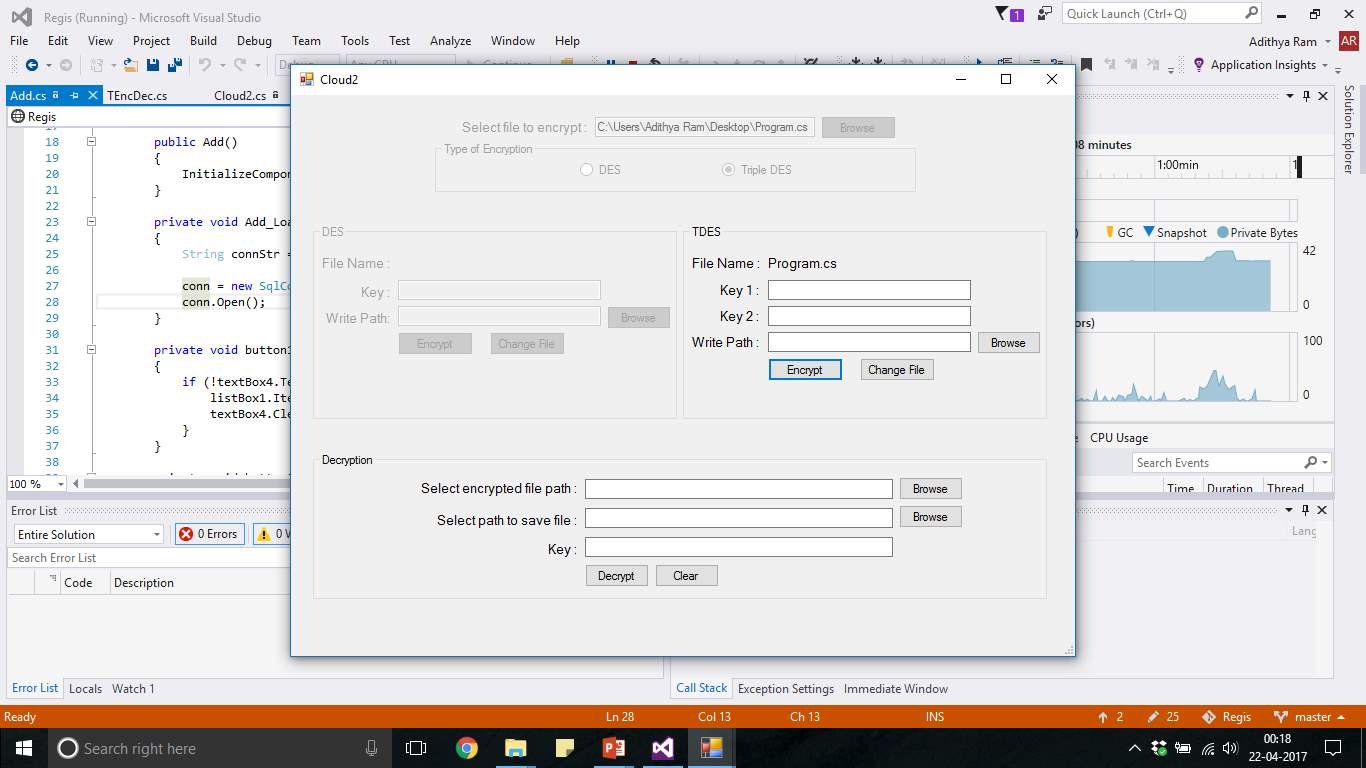
FIG 7.24 TDES Encryption
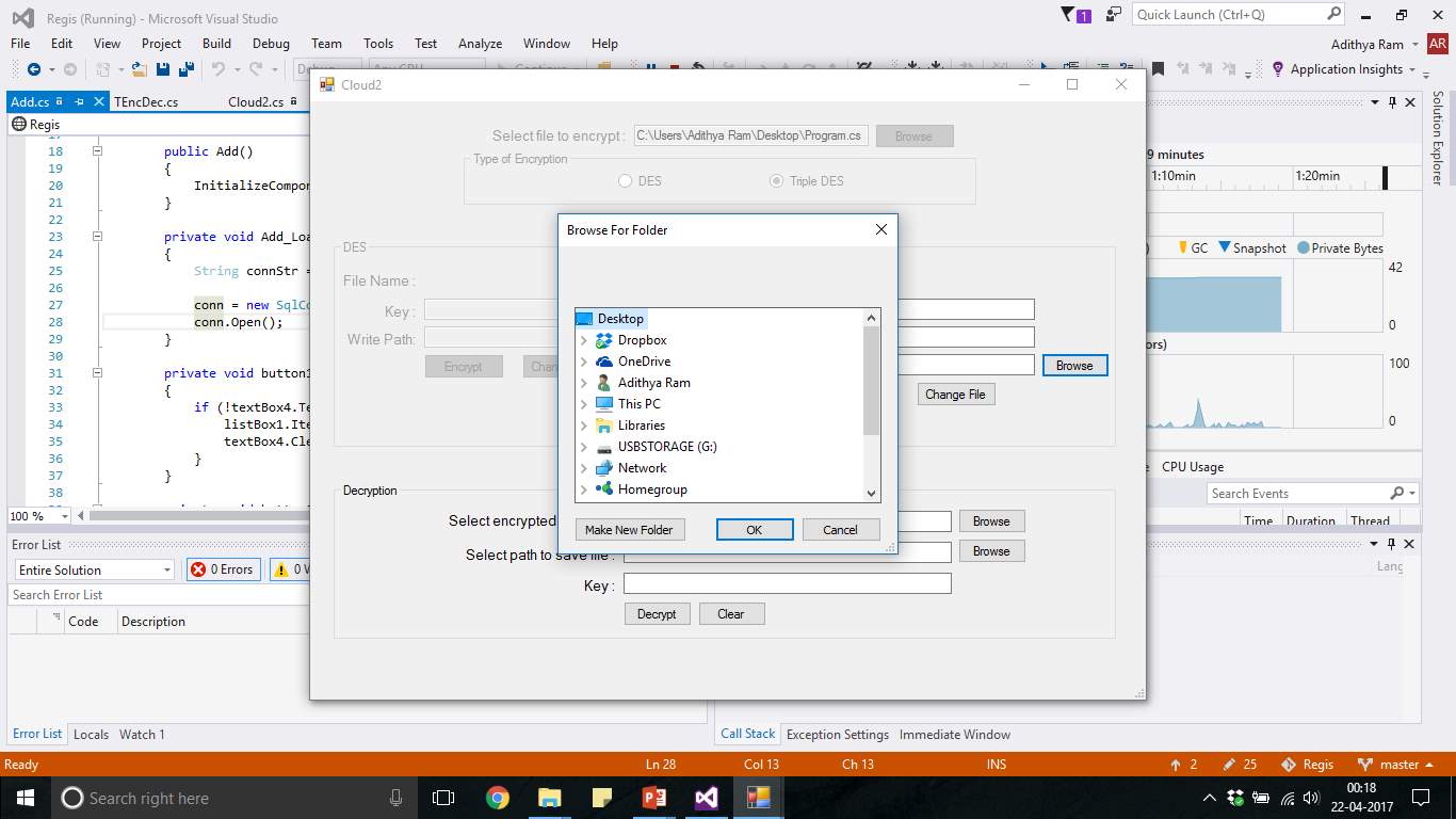
FIG 7.25 TDES Path Select
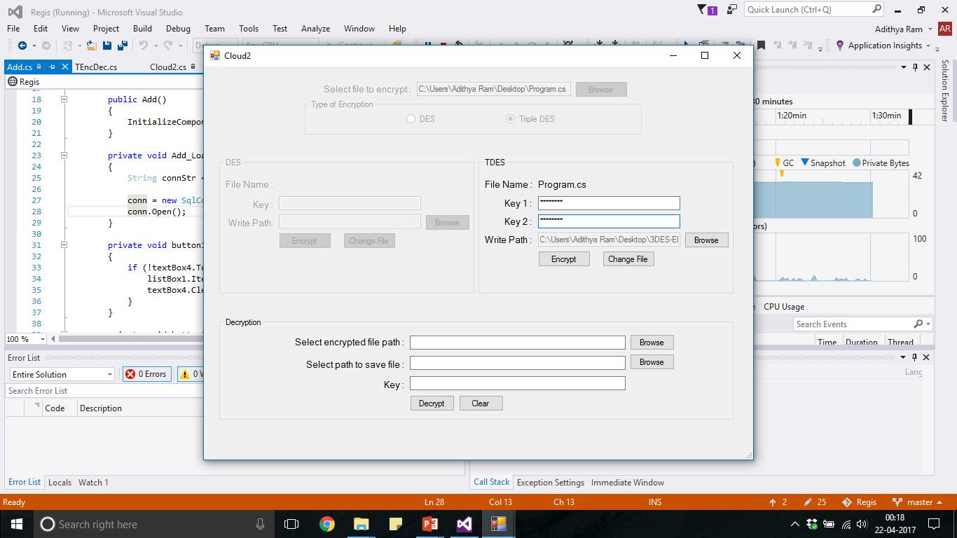
FIG 7.26 TDES Key1/Key2
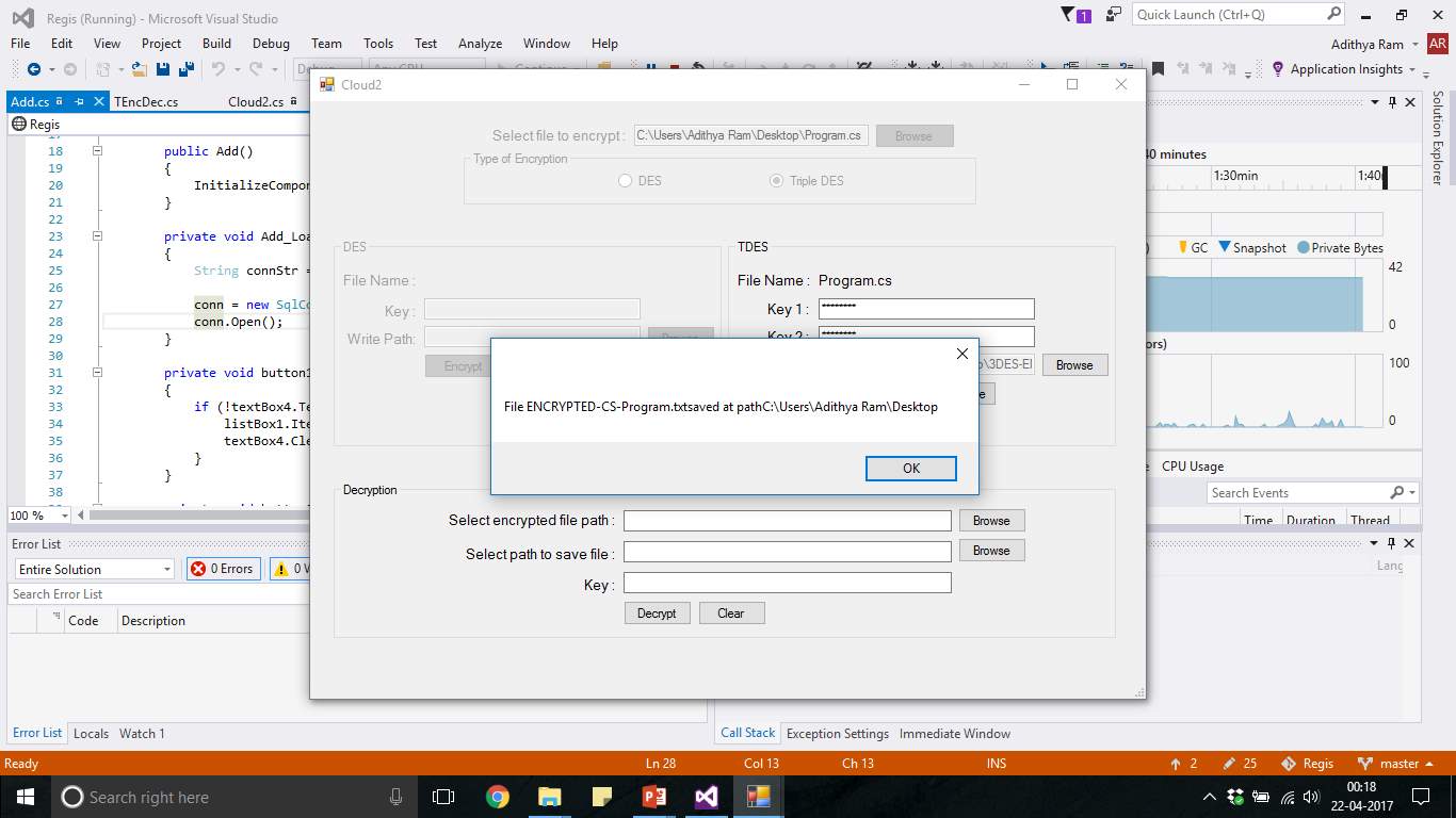
FIG 7.27 TDES File Encrypted
8. CONCLUSION AND FUTURE SCOPE
The cloud is now used for secure transfer of files between the employees of the organization. This transfer of files ensures end-end security implementation making the communication between people very secure. In this way, the security can be maintained as all the data of the organization is not compromised. And even the key transfer also happens through third party ensuring the key doesn’t fall into wrong hands there by protecting the files from attacks and threats. In this paper, we show how such information can be used effectively for the task of organization, the defence of the country and protecting the integrity of the work of the employees. Further this approach can digitalize the data that has be sitting in papers and files leading the data to be prone to be exposed to unauthorized people. We also find value in combining all the confidential data at one place in the data center making it secure through firewalls which is highly authorized and secure.
The future scope of this project can begin with making this private cloud scalable where the resources of a single user can be analyzed and scaled. By analyzing the usage of a single user, the resource pooling can be possible and only necessary resources are allocated to a user. Instead of using a symmetric key algorithm, the key of the user is not private anymore. Therefore, using asymmetric key algorithm, usage of public key and private key is more secure and the private key of the user is private and receiver gets a public key which is open for authenticated viewers.
9. BIBLIOGRAPHY
References Made From:
Amazon Cloud Storage. https://aws.amazon.com/s3
Cloud Based Data Storage www.oracle.com/Storage_Cloud_Svcs/
Wenying Zeng, Yuelong Zhao, Kairi Ou, Wei Song, Research on Cloud Storage Architecture and Key Technologies- Project under grant 2007J1-C0401, and Research Fund for the Doctoral Program of Higher Education of China grant 200805610019.
Sun Microsystems, Inc. 2009. Introduction to Cloud Computing architecture. http://www.sun.com/featured-articles/CloudComputing.pdf, White Paper, 1st Edition, June 2009:1-32.
Cloud Storage for Cloud Computing, https://www.ogf.org/Resources/documents/CloudStorageForCloudComputing.pdf
Secure Data Storage and Retrieval in the Cloud, Vaibhav Khadilkar, Anuj Gupta, Murat Kantarcioglu, Latifur Khan, Bhavani Thuraisingham, The University of Texas at Dallas
Kamara S., Lauter K. (2010) Cryptographic Cloud Storage. In: Sion R. et al. (eds) Financial Cryptography and Data Security. FC 2010. Lecture Notes in Computer Science, vol 6054. Springer, Berlin, Heidelberg.
F. Yahya, V. Chang, R.J. Walters, G.B. Wills, “Security Challenges in Cloud Storages”, Cloud Computing Technology and Science (CloudCom) 2014 IEEE 6th International Conference on, pp. 1051-1056, 2014.
Sites Referred:
https://msdn.microsoft.com/en-us/library/system.security.cryptography(v=vs.110).aspx
https://msdn.microsoft.com/en-us/library/92f9ye3s(v=vs.110).aspx
Cite This Work
To export a reference to this article please select a referencing stye below:
Related Services
View all


Related Content
All TagsContent relating to: "Cyber Security"
Cyber security refers to technologies and practices undertaken to protect electronics systems and devices including computers, networks, smartphones, and the data they hold, from malicious damage, theft or exploitation.
Related Articles

DMCA / Removal Request
If you are the original writer of this dissertation and no longer wish to have your work published on the UKDiss.com website then please: