Satellite Re-entry Analysis Tools
Info: 11921 words (48 pages) Dissertation
Published: 13th Dec 2019
Tagged: Computer Science
Abstract
Typically, when a satellite re-enters the atmosphere it is done via controlled re-entry, meaning that the time and impact location of its re-entry is predetermined. This process requires a controlled re-entry subsystem, which can be difficult and expensive to design. An alternative to this is satellite design for demise, which is the intentional design of the satellite such that it completely melts or ablates upon uncontrolled re-entry to the earth’s atmosphere. This alternative is not only cheaper and simpler, it also removes the risk of controlled subsystem failure offering a safer more reliable re-entry.
This investigation looks at some of the tools and methodology involved in design for demise, this includes the various software packages used, experiments carried out as well as the implement design changes used. These tools and methods are compared in order to best evaluate their effectiveness in producing or simulating design for demise. The design modifications were modelled and tested within DRAMA, a re-entry analysis software produced by ESA. The design changes simulated in this investigation were as follows; Component relocation, Wall thickness reduction, increased/decreased size and altered geometry. Some of these simulations were run using multiple materials, such as steel, titanium, aluminium and copper.
The results of these simulations were consistent with the research into previous work, that material selection was the most effective method for implementing design for demise. This does not mean however that the other methods are without merit, as it has shown during this investigation that they can serve to expedite the demise, in the case of a complete demise, as was the case with the wall thickness and increased/decreased size experiment. The final two experiments, component arrangement and altered geometry would require further work before their practicality can be commented on, this could be achieved using higher fidelity software or experimental testing.
Contents
2.0 Current Re-entry Analysis tools
2.1 Object orientated software
2.2 Spacecraft orientated software
3.0 Current Approaches for Design for Demise
3.1 Identification of critical parts
3.2 Structural Design for Demise
3.3 Additional Benefits for Design for Demise
4.0 Critical Analysis of current approaches.
5.0 Identification of More Promising Ideas
7.0 Implementation of Selected Approach
7.1 Component Arrangement (Exterior tank)
Nomenclature
| Ac | Casualty Cross Section |
| Ah | Average Human Cross section |
| hf | material heat of formation |
| Cd | Drag Coefficient |
| qst | stagnation point heat flux |
| V | Velocity |
| Vcirc | Circular Orbit velocity, 7.80288km/s |
| αt | thermal accommodation coefficient |
| ρ | Density |
| Kn | Knusden number |
| R | Object Nose Radius, m |
| St | Stanton number |
| Subscripts | |
| cont | continuum flow |
| fm | free molecular flow |
| trans | rarefied transitional flow |
Acronyms
| ARES | Assessment of Risk Event Statistics |
| CCS | Casualty Cross Section |
| CROC | Cross Section of Complex Bodies |
| D4D | Design For Demise |
| DAS | Debris Assessment Software |
| DRAMA | Debris Risk Assessment and Mitigation Analysis |
| ESA | European Space Agency |
| JAXA | Japan Aerospace Exploration Agency |
| MIDAS | Master(-based) Impact Flux |
| NASA | National Aeronautics And Space Administation |
| NASDA | National Space Development Agenncy (Japan) |
| ORSAT | Object Re-entry Survival Analysis Tool |
| S/C | Spacecraft |
| SARA | Survival and Risk Analysis |
| SCARAB | Spacecraft Atmospheric Re-entry and break up |
| SERAM | Spacecraft Entry Risk Analysis Module |
| SESAM | Spacecraft Entry Survival Analysis Module |
List of Exhibits
Equations
Equation 1 Bridging function for transitional flow [8]
Equation 2 stagnation point heat flux for continuum flow [8]
Equation 3 stagnation point heat flux for free molecular flow [8]
Equation 4 Casualty Cross Section [15]
Figures
Figure 1 Comparison of full re-entry and assumed re-entry [8]
Figure 3 Melting Promotion type tank [9]
Figure 4 Temperature Evolution for tests 1 & 2 [9]
Figure 5 Temperature Evolution for Tests 2 & 3 [9]
Figure 6 Temperature Evolution Arc Tunnel Testing [9]
Figure 7 Comparison of tank performance [11]
Figure 8 SARA Objection Definition
Figure 9 SARA Material Definition
Figure 10 Demise/Impact Altitude of tank
Figure 11 Surviving Mass of tank
Figure 12 Trajectory of tanks of varying wall thickness titanium
Figure 13 Demise Altitude vs time for tanks of various wall thickness
Figure 14 Demise Altitude vs distance for aluminium tanks for varying wall thickness
Figure 15 Demise Altitude vs time for tanks of various diameter
Figure 16 percentage of mass vs Diameter of tank
Figure 17 Demise Altitude vs Time for components of Various Geometry (Aluminium)
Figure 18 Surviving Mass Vs Geometry
Figure 19 Design Altitude vs time for Parts Of various Geometry for different materials
Tables
Table 1 Laser test conditions [9]
Table 2 Wall thickness and volume calculation
Table 3 Surviving mass for tanks of various wall thickness
Table 4 Table of surviving mass for tanks of varying diameter and material
Table 5 Table of Surviving Mass for various Geometries and materials
1.0 Introduction
Ever since the first launch of an unmanned satellite in 1957 the population of unmanned satellites orbiting earth has been continuously increasing and as of 2015 there are 1071 operational satellites orbiting the earth [1]. Once a satellite has completed its designated mission, if left in an orbit which is affected by atmospheric or lunisolar perturbations, will eventually re-enter the earth’s atmosphere uncontrollably. While most objects will burn up during the re-entry process heavier objects have the potential to make it to ground, at significant risk to the populace as was the case with NASA’s skylab-1 in 1979 [2]. Or more currently the Chinese space station Tiangong-1 (Heavenly Palace) which is due to re-enter the atmosphere later this year. [3]
Most satellites have to be designed for a controlled re-entry which can be a complicated and expensive process. Current safety standards at both NASA and ESA the risk to ground of any debris that has re-entered the atmosphere uncontrollably with a Kinetic Energy of 15J must be 1:10,000 (0.0001) [4]. An alternative to this which may simplify the design and reduce costs for low earth orbit missions while still meeting this standard is Spacecraft Design for Demise (D4D).
D4D is the design of a spacecraft, and/or its components, such that it will completely melt or ablate (demise) upon uncontrolled re-entry into the earth’s atmosphere. If the mass of component has been reduced to zero post re-entry then it is considered to have completely demised. If the satellite can completely demise upon re-entry then the need for a controlled re-entry would be eliminated, erasing the risk that could be generated by a controlled re-entry subsystem. [5] Not having to design and manufacture a controlled re-entry subsystem is likely to not only decrease risk but cost as well, as the controlled deorbit of a satellite such that it lands in the ocean could increase the necessary propellant up to 5 times. This would increase satellite mass (and cost) and potentially require a larger more expensive launcher. [6]
D4D became a bigger focus for NASA when they adopted a zero fault policy after the premature de-orbit of the non-demisable Compton Gamma Ray Observatory mission after one of three gyroscopes required for the controlled re-entry failed in the year 2000. The mission controllers opted to de-orbit the satellite at this point as they still had full control, which would have been lost had one more gyroscope failed. Had the S/C been demisable, the satellite could have remained in orbit in order to finish its mission. [7]
The aims of this thesis are to review and assess the current tools and methods involved in design for demise. Section 2.0 begins this by reviewing the current software tools used by various organisations to assess the demisability, the mass percentage lost upon re-entry. These software packages can be divided into two separate categories, spacecraft orientated and object orientated. All of these packages, particularly the later variety, tend to work with a number of simplifying conditions and these vary from software to software and thus the accuracy for each are considerably different.
Following this, Section 3.0 will display some current examples of applied D4D carried and D4D research out NASA and JAXA (The Japanese Exploration Agency). The success and limitations of these cases and research will be discussed by the author in section 4.0. These cases include the modification of components and satellite assembly as well as a larger study into a design modification.
Any ideas found to be more promising or less explored by the author and cases proposed by the author, will be discussed and documented in section 5.0. These ideas will be simulated and tested in DRAMA software developed by ESA, see section 6, for which a download license was provided for the purpose of this investigation. The simulated conditions for each of the tested cases is provided in section 7.0, this includes any simplifications or assumptions made.
The final results of these tests are presented in section 8.0 and discussed in section 9.0, this includes any recommendations to further or improve upon the cases presented. The final findings of this investigation are presented in section 10.0.
2.0 Current Re-entry Analysis tools
In order to accurately measure the demisability of a spacecraft several software packages have been developed to estimate the casualty risk posed by a body upon re-entry. These software packages can be divided up into two sub-categories; object-orientated and spacecraft-orientated.
2.1 Object orientated software
Object orientated methods simplify the analysis of a complete software by reducing the model to the individual components. This simplification require that only the components that are expected to survive, or those that have survived previous re-entries, need to be modelled. This is very beneficial as it vastly reduces the preparation time for any analysis. There are however several limitations to object orientated software such as that they are not able to analyse the fast heating of external parts or the protection of internal parts by the outer shells. [8]
Typically, an object orientated tool will assume a complete break up at an altitude of approximately 75km. In reality, a satellite is likely to have several break up stages both prior to and following 75km thus the risk calculated by an object orientated tool is normally taken to be a worst case scenario. [8]
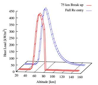
Figure 1 Comparison of full re-entry and assumed re-entry [8]
It can be concluded if a large portion of mass survives the assumed re-entry that the component would also survive the full re-entry. [8]
2.1.1 DAS
DAS (Debris Analysis Software) was developed by NASA to quickly aid their programs in mitigating risk. The spacecraft modelled in DAS are modelled as a number of simple geometric objects (Spheres, cylinders, boxes and flat plates). For the thermal analysis of the components DAS uses a lumped thermal mass model. The lumped thermal mass model assumes uniform temperature distribution for each object, thus treating each object as an individual thermal node. [8]
One of the major limitations of DAS is that it cannot simulate partial melting or ablation of an object, creating a more conservative result when compared to other tools as objects which would have their mass reduced in reality are still considered whole. All materials in DAS are assumed to temperature independent with a consistent emissivity of 1 for all materials [8].
2.1.2 ORSAT
Having also been developed by NASA, ORSAT (Object Re-entry Survival Analysis Tool) is similar to DAS such that it considers the thermal destruction by melting for selected components. The major differences are that ORSAT does consider the partial melting of a component to be a partial demise and the material properties are temperature dependant. [8]
Unlike the rest of the software packages in this category, ORSAT has the potential for multiple break up altitudes to be defined as well included the concepts of aerodynamic and thermal mass. Aerodynamic mass and thermal mass are used for trajectory calculation and heating analysis respectively. [8]
ORSAT is limited to tumbling motions or stable orientations of bodies, two conditions which produce no lift. The types of motion available to a component are limited by the primitive shape assigned to it [8].
- Spheres
- Spinning
- Not spinning
- Cylinder
- Broadside and spinning
- Random tumbling and spinning
- End-over tumbling and spinning
- Box
- Not tumbling
- Normal to the flow tumbling
- Flat Plate
- Not tumbling
- Normal to the flow tumbling
Due to the three dimensional nature of flight dynamics, the analysis carried out only has to provide coefficients of drag. The aerodynamic analysis is based upon hypersonic limits above much greater than a Mach number of 1, with Mach number independence for blunt bodies. [8]
Three times of flow regime are defined [8]:
- Free molecular flow CDfm = f(Shape, Motion)
- Rarfied transitional flow CDtrans = f(Shape, motion, Kn)
- Hypersonic continuum flow CDcont = f(Shape, motion)
A Knudsen number dependent bridging function is applied for the transitional flow region [8]:
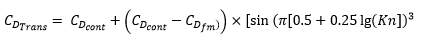
Equation 1 Bridging function for transitional flow [8]
The Knudsen number is the dimensionless parameter which is the ratio of molecular mean free path length to a representative physical length scale.
The aero-heating law also differentiates between the three flow regimes defined above. Although an averaged shape and motion dependant heat flux is assumed. [8]
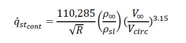
Equation 2 stagnation point heat flux for continuum flow [8]
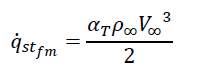
Equation 3 stagnation point heat flux for free molecular flow [8]
2.1.3 ORSAT-J
Japanese spaces agencies such as NASDA (National Space Agency of Japan) and JAXA (Japan Aerospace Exploration Agency) use a modified version of the ORSAT software called ORSAT-J. ORSAT-J has several limitations that the core version of ORSAT does not have such as that it does not consider partial melting and that material properties are assumed to temperature independent making it similar to DAS. [8] [9]
2.1.4 DRAMA/SESAM
DRAMA (Debris Risk and Mitigation Analysis) developed by ESA (European space agency) is used in similar manner to DAS will assist in several risk and mitigation analysis for various missions. The re-entry and risk analysis are carried out in DRAMA’s SESAM and SERAM modules [8], which are both incorporated into a singular module called SARA as of the DRAMA-2.0 update [10]. More details into SESAM and SERAM, as well as DRAMA as a whole, are given in section 6.0.
2.2 Spacecraft orientated software
Spacecraft orientated software are capable of modelling an entire satellite assembly as close to real design as possible. The aerodynamic and thermodynamic properties are calculated for the real complex geometries as opposed to the simplistic shapes of an object orientated software. Break ups are calculated due to thermal and mechanical loading and the shadowing of components is considered. [8]
2.2.1 SCARAB
The only spacecraft currently in use is ESA’s SCARAB (Spacecraft Atmospheric Re-entry and break up). The complex modelling within SCARAB is possible due to the hierarchy levels within the modelling system, allowing satellite systems to be built from subsystems, compounds, elements and primitives. The SCARAB modeller also provides for each of its components, the centre of mass and moment of inertia matrix, resulting in a final model of consistent geometry resembling the spacecraft. [8]
The material database within SCARAB is more extensive, at least when compared to DRAMA, having 20 physical properties. Including temperature independent properties, density, melting temperature and heat of melting. As well as temperature dependant properties such as ultimate tensile strength, elasticity module, specific heat capacity, thermal conductivity and emission coefficient. Following the re-entry the trajectory of the satellite, and later on its individual components post break up are calculated by a 6 degree of freedom analysis. [8]
2.3 Experimental Testing
Unique to an investigation carried out by a team in JAXA is the determination of a components demisabiltiy through a series of experimental tests. [9] This allows for a more realistic observation, if less precise, of how the objects and materials are affected by the heat flux and air flow. More details of these experiments are given in section 3.1.
3.0 Current Approaches for Design for Demise
3.1 Identification of critical parts
When applying D4D to an existing satellite design it is important to assess which of the components can already be described as demisable. [11] This can be done by carrying out a re-entry analysis in one of the previously mentioned software packages, or through a physical inspection of a satellite post re-entry. Any parts that survive the re-entry process are dubbed non-demisable or ‘critical parts’. [11]
Currently the most common method of applying design for demise is by applying a different material, or combination of materials, to a critical part. During one such project conducted by NASA this process was applied to a propellant fuel tank. [11]
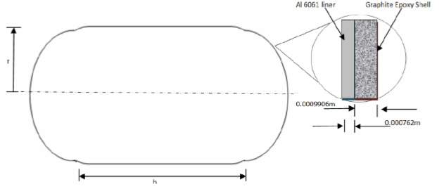
The propellant tank or COPV (Composite overwrapped pressure vessel) tank in question is dome-shaped at each end made of A1 6061 (Aluminium) of overall thickness 0.03 inches and covered with a graphite epoxy shell of thickness 0.03 inches. The masses of each material were calculated in DAS taking both the density and the volume into consideration. Through the analysis carried out in DAS and ORSAT not only was this new tank design demisable it also had a preferable mission performance as will be discussed later.
A separate group, also at NASA, carried out more in depth research on how the selection of a material could be used to implement D4D. Using Cubesats as the focus of the project, several simulations were conducted to determine how several properties of material related to one another. The main property of interest was the “Maximum Safe Mass” the amount of mass for a given material that could be used while still maintaining demisability. The goal of this project was to establish a relationship which could be used quickly and efficiently for a given geometry (CubeSats) to determine the Maximum-Safe mass. The simulations were used to compare this property to density, melting temperature and specific heat of ablation. The results of this research concluded that no simple relationship could produce the desired results. [12]
Similarly in Japan in May 2015 JAXA began working on their own demisable tank in Tsukuba city. Opposed to the aluminium and graphite used in the previous case, the JAXA demisable tank was comprised of an aluminium liner and a carbon composite. As mentioned prior, D4D is typically investigated using one of the software packages in section 2.0 however this particular project at JAXA assessed the demisability of their respective models through the use of computer simulation, JAXA assessed the demise characteristics of their model by simulating the re-entry conditions experimentally. [9] The first test carried out was a laser heating experiment.
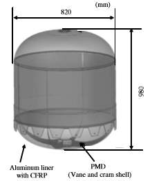
Figure 3 Melting Promotion type tank [9]
Laser heating is the process of applying heat to the surface of any material via laser. In laser heating, the most important parameters to consider are the power of the laser and the interaction time between the laser and the heated material. Typically, as the temperature of the material increases the absorption of the laser also increases. [13] The laser heating was carried out on a number of specimens which were aluminium plates joined to a carbon composite, a carbon fibre reinforced plastic (CFRP). The last was applied with two different heat fluxes and a number of different pressures, as seen in Table 1, to observe how this affected the temperature evolution on the specimens.
| Test No | Specimen | Heat Flux (kW/m2) | Irradiation Time (s) | Atmospheric Pressure (Pa) |
| 1 | CFRP & Aluminium | 200 | 60.8 | 5 |
| 2 | CFRP & Aluminium | 500 | 180.7 | 5 |
| 3 | CFRP & Aluminium | 500 | 535 | 9000 |
| 4 | Aluminium | 200 | 47.6 | 6 |
Table 1 Laser test conditions [9]
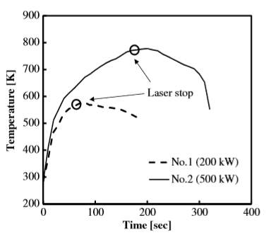
Figure 4 Temperature Evolution for tests 1 & 2 [9]
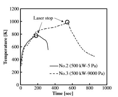
Figure 5 Temperature Evolution for Tests 2 & 3 [9]
As seen from Figure 4 above, the temperature increases sharply when the laser is initially applied to the specimen but this increase eventually slows. Estimating that the temperature would take too long to reach the melting point of aluminium the laser is switched off at approximately 80s and 200s for tests 1 and two respectively. From Figure 5 it is observed that the difference in atmospheric pressure allowed for a longer period of rapid temperature increase.
From the laser heating experiment conducted in section 6.4., it was evident that the model constructed by JAXA was not as demisable as originally assumed however as the heating was not contained within an airflow, the results differ from the real life scenario. This discrepancy lead to further testing, using the arc wind tunnel to simulate convective heat transfer. [9]
The arc wind tunnel is currently one of the world’s most useful tools in aerodynamic analysis. Capable of testing models of up to a scale of 0.5. It is unique in that it possesses its own unique model motion system creating an automated pitch, roll and yaw. [14]
The tests conducted with the arc tunnel were intended to simulate the airflow experienced by the tank upon re-entry to the atmosphere. For this test, 60 x 30 x 26 mm3 specimens of cylindrical aluminium were formed with fibres rolled onto its surface area to approximate the effect of the filament winding. Similarly, a layer of CFRP was inserted vertically between the rolled layers to duplicate the anisotropic properties of the CFRP. The layers of aluminium and CFRP were of thickness 1.0 and 1.5 mm respectively.
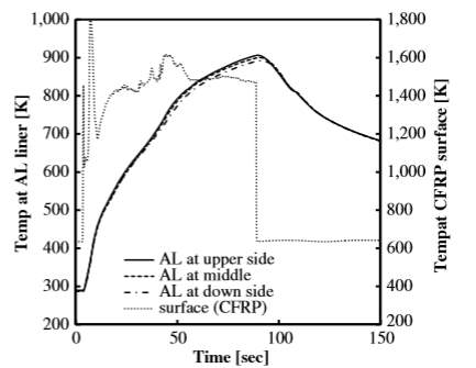
Figure 6 Temperature Evolution Arc Tunnel Testing [9]
By comparing Figure 4 and Figure 6, it can be seen that the temperature increase follows similar behaviour: with an initially high temperature increase slowing down at approximately 600K although this initial rate of temperature increase is far higher due to the airflow on the specimen.
From the two tests the authors at JAXA predicted the following demise mode. [9]
- The adhesive and resin applied between the begin to evaporate and aluminium temperature increase due to heat transfer from CFRP
- Due to either the shear stress from the air flow or thermal stress between the carbon fibres and aluminium, residual carbon fibre begins to break off.
- The broken fibres are removed due to the air flow
- With the absence of the carbon fibre the aluminium is directly heated until it melts.
3.2 Structural Design for Demise
An alternate approach that has been carried out by ESA is that rather than designing the satellite in such a way that it is more susceptible to re-entry conditions, they have designed their model in such a way that the effects of an uncontrolled re-entry are increased. [15] This can be done by triggering an earlier beak-up of the satellite to expose the inner critical parts such that they are not shielded from the heat flux. [15]
Methods of this were analysed and compared by calculating casualty cross sections (CCS) of the surviving components in each scenario. Using the CCS together with the population density and predicted kinetic energy provides an estimation of the casualty risk. D4D translates this as minimizing the amount of surviving fragments or reducing their cross sections. An alternative method of reducing risk is to reduce the amount of fragments by grouping them together into a singular larger fragment is called the design for survival approach.
The CCS is the sum of the geometric cross sections of the surviving components compared with the average cross section of the human body.
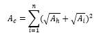
Equation 4 Casualty Cross Section [15]
Where the average human cross section Ah is taken to be 0.36m2. [15]
In the analysis done by ESA, three scenarios were created.
- The reference model. A representative model inspired by satellite design at that time.
- Central split. This model was designed such that the two larger space craft components, the service module and payload module, would separate on re-entry so that neither module protected the other from heat flux.
- Open Sided. The four smallest walls on the model, two on the service module and two on the payload module, break off from the main body prior to uncontrolled re-entry.
[15]
The efficiency of the design modifications is determined by calculating the reduction in the CCS compared to the reference module. Compared to the reference model designs 2&3 saw a reduction CCS of 37% and 47% respectively.
3.3 Additional Benefits for Design for Demise
One of the previously mentioned cases of an aluminium tank was created to investigate the additional benefits of design for demise. It was found that, as seen in Figure 7, a demisable tank was able to carry more propellant compared to a non-demisable tank of the same mass. [11] As wall thickness is kept constant, an increase in height yields an increase in tank mass. As the tank mass increases, the increase in propellant mass is greater for the demisable tank.
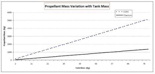
Figure 7 Comparison of tank performance [11]
4.0 Critical Analysis of current approaches.
The ideas discussed in section 2.0 while all have seen a degree of success, are limited in their exploration. In terms of broader material selection, from the research NASA has carried out on Cubesats it can be assumed that re-designing a satellite with different materials would be a lengthy process. Even then, some components such as tanks are limited in what materials can be used as all known cases involve an aluminium tank re-enforced with a second material, graphite or CFRP. These cases are also difficult as the modelling of these composite components can be difficult, as most re-entry software only consider the melting temperature of the material not its susceptibility to air resistance in the case of the CFRP.This is assuming as well that a change of material can be enforced, which is not always the case. [15]
Structural design for demise however is less explored and is equally promising. That being said, it is a much more difficult approach to explore. Due to the complexity of designing an entire satellite for structural break up, the assembly of the satellite would need to be modelled which is more time consuming. Furthermore, the structural D4D discussed in section 3.2 is based around CCS and the authors of that research admitted in their own published paper that “The uncertainties associated with a re-entry event in terms of casualty cross section are large, object depended and not well understood”. [15]
5.0 Identification of More Promising Ideas
In section 4.0 it was discussed that Structural design for demise is quite promising and is not well explored at this time. While this holds, the analysis of an entire satellite for structural design for demise would prove difficult within the limitations of this investigation. For the purposes of this investigation, the analysis is limited by the available modelling software. Both DAS and DRAMA are available commercially but as object orientated software are limited to the analysis of individual components, both software are also limited to a singular break up altitude. This limitation is not including that object orientated software are reduced to primitive shapes.
Additional for methods for D4D are described below [11]:
- Geometry
Demisability is a function of Area to Mass ratio, therefore changing a components shape to allow for a greater surface area can increase its demisability.
- Size
Changing a components dimensions to alter Area to Mass ratio, changing a components dimension to alter the mass can affect this ratio.
- Wall Thickness
Altering the wall thickness can be a useful alternative for increasing or decreasing mass as it does not affect the dimensions.
- Perforation
If any object can be perforated without compromising the structural integrity it can reduce the mass and increase the surface area. This change in the Mass to Area Ratio makes the object more likely to demise.
An object close to the centre of the satellite, inside the structural body, is exposed to re-entry conditions much later in the re-entry process than components on the outside of the structural body. If one of these components possesses a low demisability, a design can be made so that it is exposed to re-entry conditions much earlier in the re-entry phase.
An alternative to this is the break up altitude, the higher the break up altitude, the earlier the interior of the satellite is exposed to re-entry conditions.
These methods can be used individually or in conjunction with one another.
Of that list, the one found most promising by the author is item VI, component arrangement. Thus one of the proposed ideas in the following section simulates the re-arrangement of a satellite such that a critical component is placed on the exterior of the spacecraft as opposed to the interior. This allows for the component to be exposed to re-entry conditions longer rather than making the component more susceptible to them.
Some of the other presented ideas have also been used to propose cases, such as Geometry alteration, Size Adjustment, Perforation and Reduced Wall thickness.
6.0 DRAMA
The following simulations have been carried using the European debris analysis software, DRAMA. This software is usable for a number of debris risk assessment and mitigation aspects such as
- Prediction of debris or meteoroid flux on a sphere for any given object
- Determination of probabilities of no penetration for different shielding methods and the corresponding impact flux
- Prediction of any orbital uncertainties and any avoidance manoeuvres to prevent collision
- De-orbiting procedures
- Lifetime prediction (orbital)
- Analysis of atmospheric re-entry
[8]
Within DRAMA there are five modules which can run varying types of analysis.
- ARES: Assessment Of Risk Event Statistics
- Annual collision probability due to the whole population and trackable population
- Mean number of avoidance manoeuvres per year, and false alarm rate, risk reduction and remaining risk
- The calculation of ∆V required for the rate of manoeuvres and avoidance strategies
- Computation of propellant mass fraction required to fulfil the aforementioned ∆V requirements.
- MIDAS: MASTER (-based) Impact Flux and Damage Assessment
- The MIDAS software tool can be used to simulate the collision flux and damage statistics for a given mission.
- OSCAR: Orbital Spacecraft Active Removal
- A software tool used to analyse the various disposal strategies after the satellites operation life span.
- CROC: Cross Section of Complex Bodies
- The CROC module allows for the calculation of satellite cross sections from various view points on the satellite.
- SARA: (Re-entry) Survival and Risk Analysis
- The SARA module consists of two tools, SESAM and SERAM.
- SESAM, which is also referred to as re-entry is used to calculate the risks associated with the re-entry, controlled or uncontrolled, of any components that may survive the re-entry process.
- SERAM, also referred to as RISK, calculates the casualty risk assessment based on the data provided by SESAM.
- The SARA module consists of two tools, SESAM and SERAM.
[16]
As mention prior in section 2.0, the module of interest for this investigation is the SARA module. As part of the SESAM module, individual components of the re-entering object can be modelled by defining their shape, dimensions, mass and material properties as shown in Figure 8 and material properties defined as shown in Figure 9.
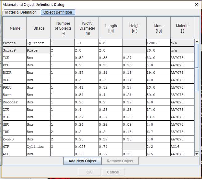
Figure 8 SARA Objection Definition
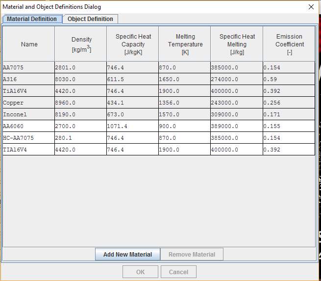
Figure 9 SARA Material Definition
The options highlighted in grey are the pre-defined and cannot be altered by the user, however up to 15 custom materials can be created. [16] The list of objects can be managed by utilising the “Add New object” and “Remove object” buttons. The dimensions and material composition of each individual component can easily be altered to enact any of the methods mentioned in section 6.0.
The motion of the individual objects following the break- up of the parent object is determined by force calculation, taking into account Earth’s gravity and the aerodynamic drag. The temperature is calculated via approximations for the heat flow as a function of local atmospheric density, velocity and ballistic coefficient. If the temperature reaches the melting temperature of that material it remains constant as the mass begins to deplete via melting. [17]
The methods used for aerodynamic and aerothermodynamic calculations are the same as used in ORAST (See section 2.0) with the differences listed below:
- The geometric shapes are limited to random tumbling and spinning
- Only lumped thermal mass model, with continuous melting (mass reduction)
- The material database is temperature independent, also oxidation heating is not considered
- The drag coefficient for Ma < 1 is simplified subsonic to 50% of the hypersonic continuum drag coefficient
- The stagnation point heat flux is simplified during the transitional flow regime.
7.0 Implementation of Selected Approach
7.1 Component Arrangement (Exterior tank)
In order to carry out simulations on an exterior tank within DRAMA several models must be used. DRAMA is limited to the analysis of the components after a singularly assumed break up at an altitude of 78km, prior to this breakup DRAMA only calculates the ballistics on a single parent object. [10]
Taking this into consideration the following set up has been devised to test the demisability of an exterior tank.
Case 1
Tank In order to approximate the behaviour of an exterior tank, all components except for the tank are removed from the Default SARA module. This allows for an effective re-entry analysis of the tank below 78km with no other components to shield it from the heat flux.
Case 2
In reality, during uncontrolled re-entry the exterior tank could be shielded from the heat flux by the main body of the satellite if that side of the satellite enters the atmosphere first. In this case, the satellite body would need to demise on its own to ensure the demise of the tank. Case 3 consists of the default SARA model without the tank.
Each of the cases detailed above were created with SARA and run to produce the following results.
7.2 Material Alteration
Experiments 7.3-7.6 have been run using multiple materials to assess how affective they are in comparison to material alteration as well as to draw comparisons to past research.
7.3 Wall thickness (Tank)
Similar to section 7.1, this section also looks at an applied D4D using a tank as its subject. In this section, the default tank within DRAMA has its wall thickness reduced to assess how this affects the demisability of the tank. As seen from Figure 8 the object definition window does not have an option for the alteration of wall thickness. Thus, in order to simulate the different wall thicknesses the tank mass at each individual wall thickness had to be calculated. This was done using the diameter of the tank (volume) and density of the material.
| Wall thickness (m) | Outer Radius (m) | inner radius (m) | volume m3 |
| 2.64E-03 | 0.225 | 2.22E-01 | 1.24E-03 |
| 2.39E-03 | 0.225 | 2.23E-01 | 1.13E-03 |
| 2.14E-03 | 0.225 | 2.23E-01 | 1.01E-03 |
| 1.89E-03 | 0.225 | 2.23E-01 | 8.94E-04 |
| 1.64E-03 | 0.225 | 2.23E-01 | 7.76E-04 |
| 1.39E-03 | 0.225 | 2.24E-01 | 6.59E-04 |
Table 2 Wall thickness and volume calculation
7.4 Wall Perforation
Perforation is the process of piercing a surface to reduce its mass while maintaining the same surface area. This is the same process applied to reducing the wall thickness, it can be assumed that perforating the walls would have similar results.
7.5 Increasing size
An alternative method for affected the surface area is to increase or decrease the size of the component. For simplicity this was done using a series of generic spheres as only one dimension could be altered.
7.6 Alternative Geometry
As the heat flux and aerodynamic drag of a component are dependent upon the cross sectional area of a component, thus the amount of melted mass and trajectory are also affected, altering the geometry can also have an effect upon the demise of an object. In order to assess this generic shapes of the same material and equal mass, , objects of equal volume and mass were constructed within DRAMA and exposed to re-entry conditions.
8.0 Results
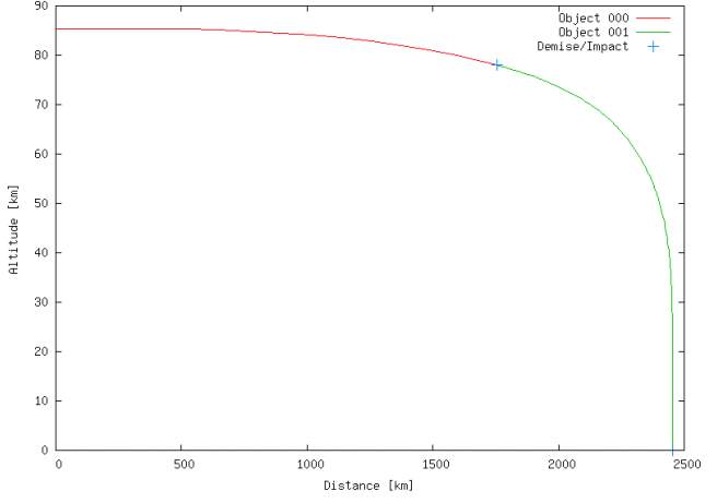
Figure 10 Demise/Impact Altitude of tank
The first demise/impact point shown in Figure 10 shows the assumed breakup of the parent object at 78km whereas the second one shows the impact point of the tank. From Figure 11 it can be seen that the majority of the tank mass survives the re-entry process, with only approximately 4% of the mass being removed by melting of ablation.
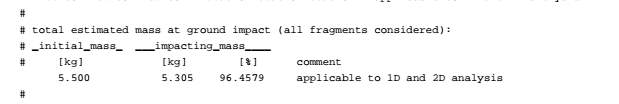
Figure 11 Surviving Mass of tank
In the case of the exterior tank presented, the initial results are quite discouraging. While the results are of a conservative nature, 95% surviving mass is still a majority of the mass. It is unlikely that even when heating prior to 78km is included that the titanium tank will demise. Due to this largely negative result, case 2 for this experiment was not run.
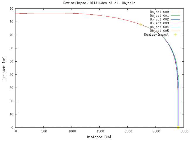
Figure 12 Trajectory of tanks of varying wall thickness titanium
| Titanium | |||||
| Wall Thickness(m) | Density | Mass | Surviving mass | Surviving mass percentage | Demise |
| 2.64E-03 | 4420 | 5.5 | 5.3108825 | 96.562% | No |
| 2.39E-03 | 4420 | 4.984487049 | 4.813095461 | 96.562% | No |
| 2.14E-03 | 4420 | 4.467814919 | 4.314189103 | 96.562% | No |
| 1.89E-03 | 4420 | 3.949982308 | 3.814162166 | 96.562% | No |
| 1.64E-03 | 4420 | 3.430987915 | 3.313013396 | 96.562% | No |
| 1.39E-03 | 4420 | 2.910830438 | 2.810741533 | 96.562% | No |
| Copper | |||||
| 2.64E-03 | 8960 | 11.14932127 | 0 | 0.000% | Yes |
| 2.39E-03 | 8960 | 10.10429954 | 0 | 0.000% | Yes |
| 2.14E-03 | 8960 | 9.05692798 | 0 | 0.000% | Yes |
| 1.89E-03 | 8960 | 8.007203955 | 0 | 0.000% | Yes |
| 1.64E-03 | 8960 | 6.955124823 | 0 | 0.000% | Yes |
| 1.39E-03 | 8960 | 5.900687946 | 0 | 0.000% | Yes |
| Steel | |||||
| 2.64E-03 | 8030 | 9.992081448 | 9.638062002 | 96.457% | No |
| 2.39E-03 | 8030 | 9.055527376 | 8.734690041 | 96.457% | No |
| 2.14E-03 | 8030 | 8.116867375 | 7.829286764 | 96.457% | No |
| 1.89E-03 | 8030 | 7.17609908 | 6.921849889 | 96.457% | No |
| 1.64E-03 | 8030 | 6.233220126 | 6.012377137 | 96.457% | No |
| 1.39E-03 | 8030 | 5.288228148 | 5.100866225 | 96.457% | No |
| Aluminium | |||||
| 2.64E-03 | 2801 | 3.48540724 | 0 | 0.000% | Yes |
| 2.39E-03 | 2801 | 3.158721317 | 0 | 0.000% | Yes |
| 2.14E-03 | 2801 | 2.831300812 | 0 | 0.000% | Yes |
| 1.89E-03 | 2801 | 2.503144897 | 0 | 0.000% | Yes |
| 1.64E-03 | 2801 | 2.174252749 | 0 | 0.000% | Yes |
| 1.39E-03 | 2801 | 1.844623542 | 0 | 0.000% | Yes |
Table 3 Surviving mass for tanks of various wall thickness
.
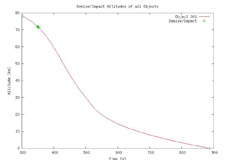
Figure 13 Demise Altitude vs time for tanks of various wall thickness
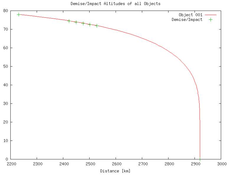
Figure 14 Demise Altitude vs distance for aluminium tanks for varying wall thickness
From Table 3 and Figure 12 it can be seen that regardless of wall thickness a titanium tank will not demise, similarly for steel. Figure 13 shows that reducing the wall thickness reduces the time taken to demise, this is due to the amount of mass required to ablate being reduced. It is worth noting that for both steel and titanium models the percentage of ablated mass remains constant despite the change in wall thickness, this could possibly be due to the lumped thermal mass approach assuming a uniform temperature distribution. Note that Figure 13 in object 001 is made out of titanium similar to the tanks in Figure 12, this is due to the code within DRAMA. When no objects survive DRAMA does not provide any plots as to their trajectory or demise altitude. Also, due to constraints within drama the time scale cannot be altered, being set at hundreds of seconds. This can make the difference in demise times less clear, Figure 14 is included as it shows the different demise points along the trajectory clearer.
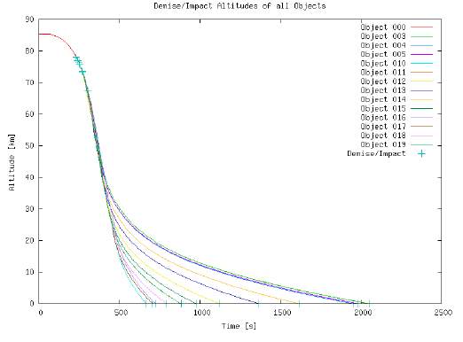
Figure 15 Demise Altitude vs time for tanks of various diameter
| Titanium | ||||
| Diameter | Mass | Surviving mass | Surviving mass percentage | Demise |
| 0.25 | 5 | 4.823 | 96.460% | No |
| 0.5 | 5 | 4.823 | 96.460% | No |
| 0.75 | 5 | 4.823 | 96.460% | No |
| 1 | 5 | 4.823 | 96.460% | No |
| 1.25 | 5 | 4.823 | 96.460% | No |
| Copper | ||||
| 0.25 | 5 | 0 | 0.000% | Yes |
| 0.5 | 5 | 0 | 0.000% | Yes |
| 0.75 | 5 | 0.556 | 11.120% | No |
| 1 | 5 | 1.582 | 31.640% | No |
| 1.25 | 5 | 2.701 | 54.020% | No |
| Steel | ||||
| 0.2 | 5 | 1.666 | 33.320% | No |
| 0.3 | 5 | 4.525 | 90.500% | No |
| 0.4 | 5 | 4.823 | 96.460% | No |
| 0.5 | 5 | 4.823 | 96.460% | No |
| 0.6 | 5 | 4.823 | 96.460% | No |
| Aluminium | ||||
| 0.25 | 5 | 0 | 0.000% | Yes |
| 0.5 | 5 | 0 | 0.000% | Yes |
| 0.75 | 5 | 0 | 0.000% | Yes |
| 1 | 5 | 0 | 0.000% | Yes |
| 1.25 | 5 | 0 | 0.000% | Yes |
Table 4 Table of surviving mass for tanks of varying diameter and material
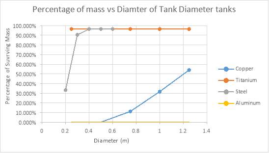 Figure 16 percentage of mass vs Diameter of tank
The results from experiment 7.3 suggest that altering the wall thickness has no effect on the percentage of surviving mass, thus the results from experiment 7.5 can be assumed to be a result of the diameter change only. The range of diameter for steel was altered from that used in the other materials as in the initial range only the 2.5m diameter result differed in terms of surviving mass.
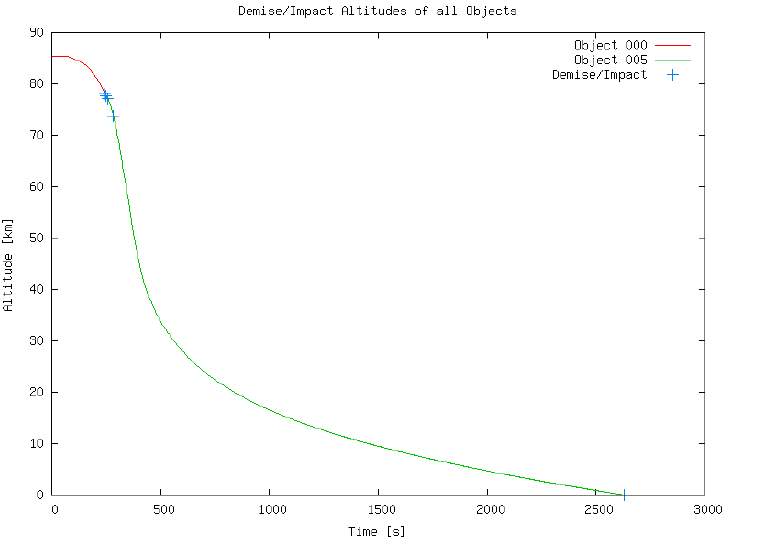
Figure 17 Demise Altitude vs Time for components of Various Geometry (Aluminium)
From Figure 17 it can be seen that for an aluminium component, the time taken to demise varies with the geometry similar to the wall thickness experiment. Unfortunately, due to constraints within the software it is not possible to determine which object demises at which point. This however can be approximated using a less demisable material. The results for all four materials is plotted and tabulated blow in Figure 18 and Table 5 respectively.
| Titanium | ||||
| Geometry | Mass | Surviving mass | Surviving mass percentage | Demise |
| Cylinder | 5.5 | 3.389 | 61.618% | No |
| Box | 5.5 | 5.305 | 96.455% | No |
| Sphere | 5.5 | 5.305 | 96.455% | No |
| Plate | 5.5 | 5.305 | 96.455% | No |
| Copper | ||||
| Cylinder | 5.5 | 0 | 0.000% | Yes |
| Box | 5.5 | 0 | 0.000% | Yes |
| Sphere | 5.5 | 1.571 | 28.564% | No |
| Plate | 5.5 | 1.435 | 26.091% | No |
| Steel | ||||
| Cylinder | 5.5 | 0.058 | 1.055% | No |
| box | 5.5 | 0.119 | 2.164% | No |
| sphere | 5.5 | 5.305 | 96.455% | No |
| plate | 5.5 | 5.305 | 96.455% | No |
| Aluminium | ||||
| Cylinder | 5.5 | 0 | 0.000% | Yes |
| box | 5.5 | 0 | 0.000% | Yes |
| sphere | 5.5 | 0 | 0.000% | Yes |
| plate | 5.5 | 0 | 0.000% | Yes |
Table 5 Table of Surviving Mass for various Geometries and materials
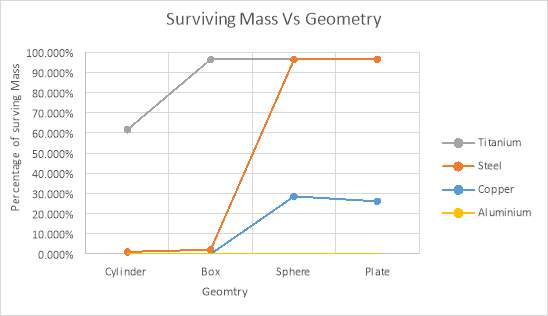
Figure 18 Surviving Mass Vs Geometry
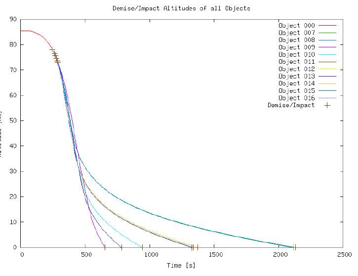
Figure 19 Design Altitude vs time for Parts Of various Geometry for different materials
9.0 Discussion
The results of the simulations carried during this investigation are consistent with previous work as it suggests that the most effective design change that can be made to produce partial or complete demise is the alteration of material. This is demonstrated by how in each test conducted during this investigation all titanium components experience a near complete survival, regardless of the alteration carried out. Similarly all aluminium components completely demise.
Based on the results of the geometry and size tests it seems that how these alterations affect the surviving mass varies with material. Observing the steel and titanium plots for these tests it can be concluded there is a point in which the rate at which material is ablated rapidly increases or that DRAMA possesses a minimum threshold for ablated mass which is higher than zero. While the surviving mass for a steel sphere does drop significantly, this does not occur until a third of its original diameter. A dimension change of this magnitude is likely to be unrealistic.
The effectiveness of a structural D4D such as the proposed external tank is still unclear. This is due to one of the key limitations of DRAMA, that the heating of the components is not considered prior to 78km. Further testing of this idea would need to be carried out to accurately comment upon its merit. Although it is unlikely that titanium could be used, as is normally the case for a standard tank in satellite design. While the exterior tank itself could be tested experimentally using a wind tunnel or laser heating, the entire satellite would likely need to be modelled in SCARAB to accurately assess how much the tank and s/c body shield one another.
While the other design methods, altered geometry, reduced wall thickness and increased/decreased size were, mostly, unsuccessful in producing a complete demise they still have use. In particular the reduced wall thickness and size experiment would be useful in providing an effective safety factor. If a component was found to completely demise after being exposed at a particular altitude during simulation, lowering the wall thickness and/or size to the minimum allowable value will allow for a margin of safety in the event the component is exposed later than anticipated. It should be noted though that depending on the function of the component, minimising this value could lower other present safety factors. The altered geometry experiment yielded mixed results, with the box and cylinder experiencing a near complete demise and the sphere and plate experiencing a near complete survival. This is likely to do with how the flow adapts to both the geometry and the motion, although it is not possible to determine further details using DRAMA. A higher fidelity tool would be recommended for investigating how the geometry could be used to affect demisability further.
Of the re-entry analysis tools found during the course of this investigation, the most advanced and least limiting software is SCARAB, the only known spacecraft orientated software developed and used by ESA. The software allows for the objects to be modelled as close to the original geometry as possible, opposed to the majority of the other re-entry tools which are limited to primitive shapes and has the option to include more material properties which are temperature independent or dependant depending on the property. These factors allow for a much more realistic image of the re-entry. The time required to build a model in SCARAB is much greater however due to the need to model the entire s/c assembly, thus it would likely be beneficial to run preliminary analysis in DRAMA to determine which parts are critical and need to be modelled in more detail. The aerodynamic and aerothermodynamic calculations are also more complex, using a six degree of freedom analysis. SCARAB is also capable of modelling the joining of the individual components, calculating heating prior to 78km and controlling the defined break up altitude, making it the most suited tool for simulating structural design for demise.
Of the object orientated codes however, the most effective is likely to be the core ORSAT program used by NASA. It can be seen to be a less limited version of DRAMA as it can model more motions for various geometries and can consider 1 dimensional heat conduction. Unlike DRAMA ORSAT also considers oxidation heating. The simplification of translational heat flow in DRAMA is also not made within ORSAT as the bridging function is dependent upon the geometry.
While DAS is likely to be the least useful of the software found in this investigation due to its in ability to process partial demise it is commercially available similar to DRAMA. One of the initial aims of this investigation was to compare the results of similar simulations in both DAS and DRAMA in order to create a visual representation of how the limitations within the software affects the results. However due to the time constraints of the investigation and the time in which the software license for DAS was granted this was not feasible.
Many of the results are limited determined by the limitations of the software. Such as the pre-defined break up altitude of 78km and that the rate at which is mass is lost cannot be plotted or defined (although for the wall thickness experiment this would like be constant due to the assumed uniform temperature distribution assumed by the lumped thermal mass model).
As previously stated, the most commonly explored method of implementing a design for demise is the use of a more demisable material. While this is true, due to the limitations of the software tools currently used, the use of composite materials is not as explored. This is also true for materials with complex properties, such as tungsten which while having the highest melting temperature of any known metal produces a flammable dust which increases the rate of heat flux. In order to further investigate this, experiments like the ones carried out during the JAXA investigation would be recommended. Other materials should be tested in place of the CFRP in that model to see how the different material heat conduction coefficients affect the demise of aluminium tank.
10.0 Conclusions
This purpose of this investigation was to identify and assess the various tools and methods used in satellite design for demise. From this, several software packages used in simulating how a spacecraft is affected by re-entry into the earth’s atmosphere. Software used in this field was found to be divided into two categories, object orientated and spacecraft orientated. While all the software packages come with their own limitations and merits it was concluded that the least limiting of the current software packages was ESA’s SCARAB which is the only spacecraft orientated tool currently in use. Alternatively, though not as common, experimental testing has also been used to test design for demise. While more expensive than the simulation packages, the experimental apparatus described may provide more accurate data for how different materials may be affected by re-entry conditions.
During the research section of this investigation, it was found that changing the materials that a given component was comprised off was the most common method for applying design for demise. Other methods for D4D were found, presented and tested using the re-entry analysis module of a software developed by the ESA. These methods and their results are listed below:
- Component Arrangement
One of the least explored ideas in design for demise is structural design for demise. This idea was simulated here using component re-arrangement. Due to the limitations of the software used this had to be done by studying the effects on a single component, in this case a propellant tank which is typically comprised of titanium. From this it was concluded that a material change would still be necessary but further work using more advanced software or experimental testing would be required to determine the effectiveness and which materials could be used.
- Wall Thickness
By reducing the wall thickness of a component while maintaining a constant area reduces the total mass of the component. The results given by DRAMA for this experiment suggest that lowering the wall thickness of a component cannot demise a component comprised of titanium. It can however reduce the time taken to demise for a component made of a more demisable material, such as aluminium.
- Alternate Geometry
As the forces on a component during re-entry conditions are either aerodynamic or aerothermodynamic they are dependent upon the cross sectional area facing the airflow. One way of affecting the cross sectional area is to use an alternative shape when possible. Four simple shapes of equal mass and of the same material were exposed to re-entry conditions. The results do prove that altering the geometry can influence the surviving mass but are inconsistent due to the limitations of the software.
- Increasing/Decreasing size
A series of simulations were run on spheres of various cross section area (by varying the diameter) to assess how this change in cross section of constant shape affected the amount of ablated mass. Due to the results of the wall thickness experiment it was concluded this simulation could be run with constant mass for simplicity. Similar to the wall thickness experiment, all titanium objects experience near complete survival while aluminium experiences near complete demise. Both steel and copper however see a decrease in surviving mass when diameter (and thus cross section) is reduced. For steel, the decrease does not occur until 50% of its original diameter, with a more significant decrease observed at 33%.
It is recommended by the author that each test be re-run using different software or using the experimental apparatus detailed in section 3.0. For the wall thickness experiment, it would be most advantageous to re-run in a condition where the lumped thermal mass approach is not applied as it would confirm whether or not the wall thickness would affect rate at which the mass melts and ablates. If this is the case, the size experiment would need to be re-evaluated under conditions where the variation in wall thickness is considered. The alternative geometry test would need to re-done in an environment where the rate of melting and ablation can be observed and where the motion of the objects is unrestricted.
References
| [1] | F. Cain, 23 December 2015. [Online]. Available: http://www.universetoday.com/42198/how-many-satellites-in-space/. |
| [2] | E. Hanes, “The Day Skylab Crashed to Earth: Facts About The First U.S Space station’s Re-entry,” history , 11 July 2012. [Online]. Available: http://www.history.com/news/the-day-skylab-crashed-to-earth-facts-about-the-first-u-s-space-stations-re-entry. [Accessed 11 Feburary 2017]. |
| [3] | T. Phillips, “China’s Tiangong-1 Spacestation ‘out of control’ and will crash to Earth,” the guardian , 21 September 2016. [Online]. Available: https://www.theguardian.com/science/2016/sep/21/chinas-tiangong-1-space-station-out-of-control-crash-to-earth. [Accessed 11 Feburary 2017]. |
| [4] | NASA, “NASA-STD-8719.14A,” 2011. [Online]. Available: http://www.hq.nasa.gov/office/codeq/doctree/871914.pdf. |
| [5] | M. E. J. A. Peter M.B Waswa, “Spacecraft Design-for-Demise Implementation stratgey & decision-making methodology for low earth orbit missions,” 2012. |
| [6] | “Design for demise – A first look,” 24 February 2016. [Online]. Available: http://m.esa.int/Our_Activities/Space_Engineering_Technology/CDF/Design_For_Demise_A_First_Look. |
| [7] | P. W. M/B, “Spacecraft Design-for-Demise Strategy, Analysis and Impact on Low Earth Orbit Space Missions,” International Space University, 2005. |
| [8] | B. F. Tobias Lips, “A comparison of commonly used re-entry analysis tools,” Acta Astrinautica 57, pp. 312-323, 2005. |
| [9] | I. M. K.-i. K. Tadashi Masuda, “Demise Characterists Evaluation for Melting Promotion-type tank,” Journal Of Propulsion and Power, Tsukuba City, 2015. |
| [10] | ESA, DRAMA Final Report, 2014. |
| [11] | J. H. Peter Wasa, “Illustrative NASA Low Earth Orbit spacecraft subsystems design-for-demise trade-offs, analyses and limitations,” International Journal of Design limitations , 2012. |
| [12] | D. J. R.L. Kelly, “Cubesat Material Limits for Design for demise,” 2015. |
| [13] | “what is laser heating?,” TWI (The welding Institute) , [Online]. Available: http://www.twi-global.com/technical-knowledge/faqs/process-faqs/faq-what-is-laser-heating/. [Accessed 10 November 2016]. |
| [14] | “The Arc Wind Tunnel,” ARC Auto Research Centre , [Online]. Available: http://www.arcindy.com/wind-tunnel.html. [Accessed 10 November 2016]. |
| [15] | Q. F. H. K. Stijin Lemmens, “On-ground Casualty risk recuction by structural design for demise,” COSPAR, Darmstadt, 2014. |
| [16] | European Space Agency, DRAMA Software User Manual, 2014. |
| [17] | “DRAMA/SESAM,” HTG Hyperschall technologie gottingen gmbh, [Online]. Available: http://www.htg-hst.de/1/htg-gmbh/software/dramasesam/. [Accessed 14 March 2016]. |
| [18] | “What are SmallSats and CubeSats?,” 26 Fed 2015. [Online]. Available: http://www.nasa.gov/content/what-are-smallsats-and-cubesats. |
| [19] | “Tungsten,” pt.chemicalstore, [Online]. Available: http://pt.chemicalstore.com/W%20-%20Tungsten.html. |
Cite This Work
To export a reference to this article please select a referencing stye below:
Related Services
View all


Related Content
All TagsContent relating to: "Computer Science"
Computer science is the study of computer systems, computing technologies, data, data structures and algorithms. Computer science provides essential skills and knowledge for a wide range of computing and computer-related professions.
Related Articles

DMCA / Removal Request
If you are the original writer of this dissertation and no longer wish to have your work published on the UKDiss.com website then please: