Development of a Rotational Movement Mechanism Against External Vibrations
Info: 17667 words (71 pages) Dissertation
Published: 16th Dec 2019
Tagged: EngineeringMechanics
Development of a rotational movement mechanism able to reach and maintain the desired position (multi-stable position mechanism) against external vibrations, by the usage of shape memory alloy (SMA) technology
i. Preface
This thesis is the final proof of competence for obtaining the Master of Science (MSc) degree in Scientific Instrumentation at Ernst-Abbe-University of Applied Sciences, Jena, Germany. It is a mandatory requirement to carry out a research thesis for minimum of 18 weeks to gain good practical work experience. It was a wonderful opportunity for me to showcase my talents in a reputed organization, Actuator Solutions GmbH, to benefit from the experience and expertise of the company, and to learn and further develop a new set of skills. In this Master’s thesis, I described my practical experiences with the latest technologies during the thesis period.
ii. Confidential Clause
This final thesis is based on internal, confidential data and information of Actuator Solutions GmbH. This work may only be made available to the first and second reviewers and authorized members of the board of examiners. Usage of the work in this master thesis in any format or medium, including print and electronic media, without due permission from the author and from Actuator Solutions GmbH would be considered as legal violation of the act, which may lead to jurisdictional convictions.
v. Abstract
Shape memory alloys (SMA) are fascinating due to their unique property of remembering shape. A decade’s study of SMA has led to solutions and developments that have used it in engineering application in a variety of forms, such as SMA wires and springs. SMA wires are widely used in actuators as active components, which can fulfil a wide range of applications in different sectors, including automotive, white goods, medical, telecommunications etc. The implementation of SMA technology in an actuator can deliver a very promising alternative to the traditional actuator because of its simple, quiet, and light-weight construction.
Head Up Displays (HUD) used in the automotive industry currently run using conventional actuators based on a stepper motor and gear system to achieve the required rotation. Due to the usage of a gear system, along with a stepper motor, these systems produce a high level of noise. The market is now replacing them with alternative solutions that reduce or completely remove any noise during the movement.
This paper discusses a new approach to develop a mechanism – namely that of a SMA‑driven actuator – that is able to provide a rotational controlled movement and maintain the desired position by the use of frictional behaviour against external vibrations. This mechanism will be applied to the HUD inside the car and will provide the required rotational movement to the mirror, which will then project the message onto the wind shield.
vi. Acronyms
ABS Acrylonitrile Butadiene Styrene
ASG Actuator Solutions GmbH
CAD Computer Aided Design
CNC Computer Numerical Controlled
FDM Fused Deposition Modelling Technology
HUD Head Up Display
IC Integrated Circuit
NdFeB Neodymium Magnet (Neodymium Iron Boron)
NiTi Nickel Titanium
NiTiNol Nickel Titanium Novel Ordinance Laboratory
O/P Output
PA Poly Acrylate
PCB Printed Circuit Board
POM Polyoxymethylene
SMA Shape Memory Alloy
SME Shape Memory Effect
vii. List of Symbols
Symbol Unit Description
A – Austenite
M – Martensite
Mt
– twinned martensite
Md
– detwinned martensite
Mf
⁰C Martensite finish temperature
Ms
⁰C Martensite start temperature
Af
⁰C Austenite finish temperature
As
⁰C Austenite start temperature
MPa Stress
t ⁰C Temperature
f
MPa detwinning finish stress
s
MPa detwinning start stress
% Strain
L mm Length
d mm Diameter
r mm radius
A
mm2 Area
F N Force
α ⁰ Angle
Mt N-m Torque
m Kg mass
Fs
N Spring force
VH
V Hall voltage
g
ms2 acceleration due to gravity
M Nm Moment
R Resistance
mm Resistivity
viii. List of figures
Figure 1: ASG Headquarters in Gunzenhausen
Figure 2: Temperature induced phase transformation of a SMA without mechanical loading [11]
Figure 5: One way shape memory effect
Figure 6: Two-way shape memory effect
Figure 7: Standard wire diameters and their corresponding values [17]
Figure 8: Typical electrical actuation, time vs stroke [18]
Figure 9: Life cycle behavior under stress-strain [19]
Figure 10: SMA wire in U-shape geometry
Figure 11: SMA wire in V-shape geometry
Figure 12: Tool feeding the part in a CNC machine
Figure 13: Parts before and after manufacture
Figure 14: Injection Molding Machine [26]
Figure 15: Schematic representation of a Head Up Display [34]
Figure 17: Rotational motion mechanism in initial design
Figure 18: Braking mechanism in initial design
Figure 19: Braking mechanism detailed view
Figure 20: Customer specified dimensions
Figure 21: Final actuator rotational mechanism
Figure 22: Final actuator rotational mechanism
Figure 24: Pin orientations at various positions
Figure 25: Stress and strain values from lifecycle graph
Figure 27: SMA wire in U-shape
Figure 28: Wire length before and after activation
Figure 29: Final actuator brake release mechanism views
Figure 30: Final actuator brake release
Figure 31: Final actuator assembled to mirror
Figure 32: SMA in V-shape configuration
Figure 33: Stress and strain values from lifecycles graph
Figure 34: Hall sensor assembly in actuator
Figure 35: Hall effect sensor principle [35]
Figure 36: Hall sensor position in PCB
Figure 37: Typical magnet and magnetic flux distribution [41]
Figure 38: Final actuator exploded view
Figure 39: Overall dimensions of final actuator
Figure 40: Final actuator major assembling steps
Figure 41: Driving wheel assembly
Figure 43: Driven wheel assembly
Figure 44: Final assembly sequence
Figure 50: Extension spring dimensions
Figure 52: Housing bottom cover
Figure 53: SMA wire crimping with fasteners
Figure 54: Special crimp dimensions
ix. List of tables
Table 1: Angles corresponding to mirror position
Table 2: Wire lengths corresponding to the mirror angular positions
Table 3: Minimum wire lengths for corresponding strain values
Table 4: Stress and strain when life cycles > 100K
Table 5: Bill of materials final actuator
Table 8: Material properties RGD 835
Table 9: Mesh information RGD 835
Table 10: Material properties POM
Table 11: Mesh information POM
Table of Contents
2.1.3 Phase Transformation in Shape Memory Alloys
2.2.4 Selection of plastic part materials
3 Actuator Design and Development
3.5 Part dimensions and material selection
3.6.2 Crimping using fasteners
3.6.3 Fastening with specially designed crimps
3.7 Analysis of snap using solid works simulation
3.7.1 Simulation using material Verowhite RGD 835
3.7.2 Simulation using material POM
3.7.3 Analysis results conclusion
A. Injection moulding material properties
D. Actuator Assembled with HUD Mirror
E. Data sheet verowhite plus RGD 835
F. Hall sensor AS5048 data sheet
Overview of the chapters
This thesis is structured as follows:
Chapter 1: Introduction
An introduction to the thesis is given in which the goals and objectives, scope, and limitations of the project are discussed and a small overview of the company where this thesis is performed is given.
Chapter 2: Literature study
The study mainly focuses on theoretical understanding, which will help in better understanding and implementing suitable technology during development of the project. The two main technologies used are: Shape Memory Alloy (SMA) and plastic fabrication methods. The properties of SMA are discussed, such as transformation temperatures, shape memory effect (SME), and formulas helpful in implementing SMA wire in different geometries. For plastic fabrication methods, the working and selection of different production methods are discussed, depending upon the required quantity and properties of the part. A discussion is also provided of the advantages of one technique over another.
Chapter 3: Actuator design and development
This chapter provides an evolution of the actuator, explains the heads up display, and the development of the actuator in which different mechanisms are designed and calculations can be performed by considering initial inputs and final inputs. The workings of a Hall sensor are explained and it is discussed how it can be used in this project to measure the angular movement. A bill of materials with dimensions of parts and material selection is described. In a further section, the different methods that can be used to fastening the SMA wire are explained and finally an analysis is carried out on the housing top cover snap. Lastly, the results are given and conclusions deliberated.
Chapter 4: Future work and conclusion
This briefly discussed continuation of the work by taking the best results from two designs and developing an actuator for real working conditions. A conclusion is given by observing the results.
1 Introduction
Researchers have been developing shape memory alloys (SMA) for decades, but despite this there are still not many SMA-driven actuators available on the global market. A few existing SMA-driven actuators have excellent positive properties, such as being light weight, occupying less space, and having large working capacity per volume. The company Actuator Solutions GmbH (ASG) develops and produces actuators based on SMA technology. The SMA wire is the active component for each of these actuators. Such actuators are able to fulfil a wide range of applications in different sectors (such as automotive, white goods, medical and telecommunications). The products using SMA technology are a promising alternative to conventional actuators. One of the applications is in Head-Up Displays (HUD). HUDs are currently used in the automotive industry, which uses a tradition actuator based on an electrical stepper motor and gears system to produce the required rotation. Due to the high level of noise produced by the gear system during movement, the market is now looking towards alternative solutions to reduce or completely remove any noise during the movement. In this thesis, one of the SMA-driven actuators that can replace the electric motor in the HUD is discussed.
1.1 Goals and Objective
The main goal of this master’s thesis is to develop a rotational movement mechanism able to reach and maintain the desired position against external vibrations by the usage of SMA technology. This mechanism can be applied to the HUD inside cars and will provide the rotational movement to the mirror (display), which then will project the text onto the wind shield (magnification mirror).
Starting from preliminary customer technical requirements, notably in terms of respecting the geometrical constraints and assuring accurate working conditions, a new mechanism is completely designed.
The main objectives of this thesis investigation include the following:
- Understanding and converting the technical product requirements into a preliminary mechanical sketch;
- Performing the SMA wire calculations (minimum length and diameter needed to meet the specifications);
- Designing a preliminary concept mechanism (including parts design and assembly with the help of CAD software SolidWorks);
- Defining the BOM mechanism (Bill of materials), and selecting the best materials and technologies to produce each single component;
- Performing and verifying the design through FEM simulations wherever it is necessary;
- Realizing a prototype to prove the concept design mechanism and performing functional tests;
- Iteratively modifying and improving the design, based on test results.
1.2 Scope and Limitations
This thesis work will concentrate only on the design and development of the SMA wire driven rotary actuator, not on the electronics and the software that are needed to control the device for small steps. The electronics and software part of this project is supported by the Electronics Department.
One of the biggest challenges for this project is to define a mechanism capable of performing the rotational movement within a defined and precise number of small steps and maintaining the desired position only by the effect of friction between the materials involved in the engagement. This is completely dependent upon the precise dimensions and quality of the parts.
One limitation is the duration of the thesis, as within the given time frame it is only possible to produce a device that can give satisfactory results in laboratory conditions, not in real-world conditions. Vibrations due to the speed of the car will negatively affect the stability of the desired position but, if further time is possible, special materials could be used to guarantee performance.
1.3 Company Profile
Actuator Solutions GmbH

Figure 1: ASG Head Quarters in Gunzenhausen
Actuator Solutions GmbH (ASG) is an international company headquartered in Gunzenhausen, a small city in the German state of Bavaria. In 2011, the company was established at Treuchtlingen and later in 2013 it moved to Gunzenhausen. This company is a joint venture between two leading companies: one the Italian company “SAES Getters” and the other a German company “Alfmeier Präzision AG” [1]. “SAES Getters supply and manufacture the SMA trained wires, springs, components and Alfmeier Präzision develops and mass produces SMA actuators” [2]. These two companies are highly successful in their respective fields. ASG contributes to introducing modern technology to current market needs by producing numerous actuators based on SMA for the replacement of motors and electromagnetic actuators in various fields, such as automotive, white goods and consumer electronics [3]. The concept design and development takes place in the Mechanical Department and once initial design is finalized, the design is printed by the Shop Floor Department for functional testing. The Electronics Department provides support for further stages involving electronics and software to control the mechanism. The company has all the required facilities under one roof to design and test the part inhouse, which saves a lot of time in the production of the final part. This extensive R&D makes ASG a successful manufacturer of SMA actuator and valves in Europe and Asia. “The mission of Actuator Solutions is to increase the worldwide market and technology leadership in SMA actuators by serving the needs of the industrial market, leveraging the integrated internal value chain” [4].
2 Literature Study
Before starting actual design, a theoretical study was undertaken on SMA, plastic parts fabrication techniques, and Hall sensors. This helped in providing a better understanding and allowing the design of the actuator to produce positive results.
2.1 Shape Memory Alloys
A superior type of material that have an exceptional ability to memorize their shape are shape memory alloys, or simply SMA. “This means that these alloys plastically deform at one temperature and they will completely recover their original shape on being raised to a higher temperature” [5]. The required shape of these materials at a specific temperature (generally, this temperature is lower or in a cold state) is defined prior to positioning in a temperature where they can easily be deformed. When a SMA is heated to higher temperatures, the order of crystal structure changes and this causes it to go back to its initial shape [6]. In the process of recovering their shape the alloys can produce a displacement or force as function of temperature.
NiTiNol (Nickel Titanium Novel Ordinance Laboratory) alloys are a widely-used SMA. Nickel-Titanium alloys exhibit the greatest resistance to effects, in adding to satisfactory properties of elasticity, malleability and fatigue. These alloys have a capacity of maximum 5% strain recovery and persist for a substantial number of life cycles. NiTiNol alloys are electrically conductive and when an electrical current is applied it shows some resistance. Because of the heat this produces, this helps lead to a change of crystal structure at higher temperatures. Normally, the selected crystal change temperatures are above atmospheric temperatures.
There are some boundaries to SMA use in engineering applications. As NiTiNol alloys can accurately yield small displacements, these are more appropriate for small applications. “The Actuators functional behaviour of the NiTiNol alloys are highly influenced by the factors like force, temperature, displacement and number of life cycles” [7]. Motors or solenoids are used in areas where continuous movement or large displacement is essential. In the market, many companies are capable of producing NiTiNol in various forms, notably wire and springs. Actuator Solutions GmbH is one of the companies that develop various kinds of actuators using SMA in wire or springs for the telecom and automotive industries.
2.1.1 Nitinol History
In the 1890s, a scientist called Adolf Martens discovered martensitic behaviour in steels, which led to the discovery of SMA. These alloys were unutilized until 1963, when it was discovered that these alloys exhibited reversible martensitic transformations [8]. The discovery of NiTi alloys happened accidentally when Beuhler and his co-worker were conducting experiments on a material that was suitable for heat shielding. Through experimental developments, NiTi materials were discovered to have shape memory properties and to possess good mechanical and better fatigue properties than other alloys. The new alloys were named as NiTiNol by scientists, as the alloy was a combination of Nickel and Titanium and had been discovered at the Naval Ordinance Laboratory. After discovering NiTiNol alloys, a series of experiments took place to evolve SMAs.
2.1.2 Working principle
SMA work by changing their crystal structure (phase transformation) when exposed to certain temperatures. These alloys are tuned by holding them in a desired shape at an elevated temperature (the austenite phase), and then when they cool they transform to the martensitic phase without changing shape. Upon applying a load, the alloys plastically deform at one temperature and they will completely recover their original shape on being raised to a higher temperature [9]. In recovering their shape, SNA can produce a displacement or a force as a function of temperature.
In this master thesis, NiTi-based SMA wires were used as they exhibit a greater resistance to impact in addition to satisfactory properties of elasticity, malleability and fatigue.
2.1.3 Phase Transformation in Shape Memory Alloys
SMAs have two different phases of transformation when exposed to certain temperatures. The two phases have different properties with different crystal structures.
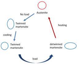
The first is the Austenite (A) phase, which is seen at elevated temperatures and exists in cubic crystal structures. The second phase is the martensite (M) phase, which is seen at low temperatures and can exist in tetragonal, orthorhombic, or monoclinic crystal structures. In martensitic transformation, the transformation among the structures occurs by shear lattice distortion rather than diffusion of atoms. “Each martensitic crystal formed can have a different orientation direction, called ‘variant’” [10]. When the variant is formed by the self-accommodated martensitic then it is called twinned martensite (
Mt): this occurs when the system is in a ‘no load’ condition. When the variant is formed by a reorientation of a specific variant then it is called detwinned martensite (
Md): this occurs when the system is in ‘load’ condition. The shape recovery is observed when the reversible phase transformation occurs i.e. when the transformation happens from parent (Austenite) to product phase (martensite) and vice versa.
Phase transformation when no load condition
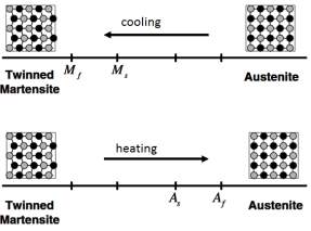 In the absence of load when the material is cooling, the crystal structure changes during the phase transformation from austenite to martensite. This is called forward transformation. Upon heating the material from the martensitic phase, the crystal structure changes back to austenite and this is called reverse transformation. Throughout this process the material will not change its shape [12].
Figure 2 shows the transformation between twinned martensite and austenite phase and their crystal structures. When the load is zero, during cooling (forward transformation) the transformation from austenite to twinned martensite starts at the martensitic start temperature (
Ms) and completes the transformation at the martensitic finish temperature (
Mf). Here the material is fully in the twinned martensitic phase. Similarly, when the material is heated the reverse transformation starts at the austenitic start temperature (
As) and ends at the austenitic finish temperature (
Af).
Phase transformation during load condition
The Figure 3 shows that, in the twinned martensitic phase, if the material undergoes a certain loading condition, the crystal structure orientation changes, forming detwinning martensite. The change of shape happens at the microscopic level, and once the load is released the material regains its deformed shape (showed in Figure 4). “A subsequent heating of the SMA to a certain temperature above
Afwill result in a reverse phase transformation (from detwinned martensite to austenite) and will lead to complete shape recovery” [13]. When the temperature falls back to below
Mfthen it transforms to the twinned martensite phase without any deformation in the shape.
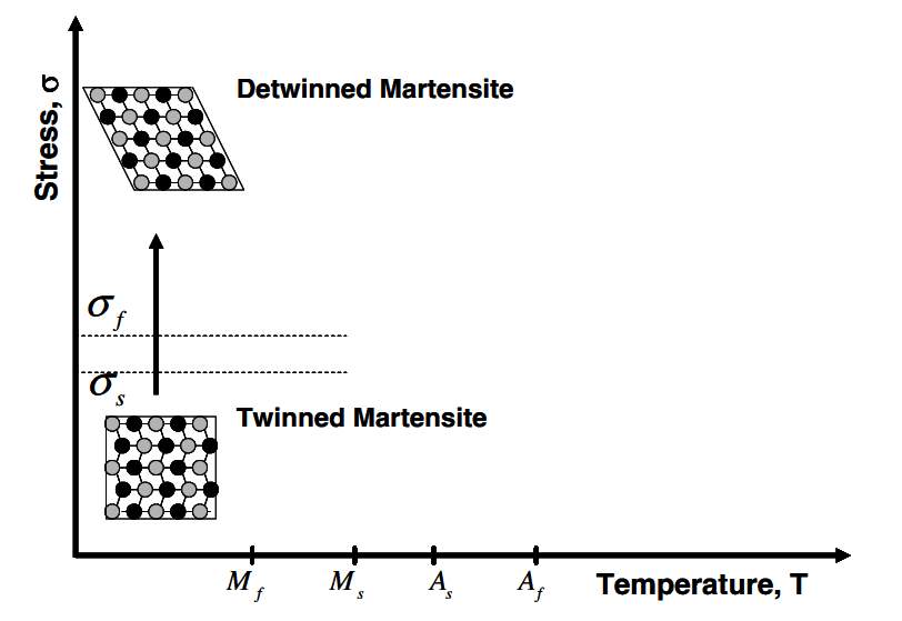
Figure 3: shape memory effect of an SMA showing the detwinning of the material with and applied stress [14].
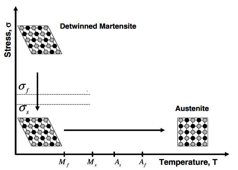
Figure 4: shape memory effect of an SMA showing the unloading and subsequent heating to austenite under no load condition [15].
2.1.4 Shape Memory Effect
If the load is applied to the material, when it is in twinned martensitic phase it distorts its shape and if the load is removed while cooling below the austenite start temperature (
As) and removed again when it is heated above the austenite finish temperature (
Af), the SMA will transform back to the austenite phase by gaining its original shape. This effect is called the shape memory effect (SME) [16]. The SME exists in two forms:
One way SME
 Figure 5 presents a graphical example of one way SME. In martensitic phase or cold phase when the load is applied to SMA, it deforms. This deformation is seen until the system is heated higher than the transformation temperature. When the system is heated again to a temperature greater than the transformation temperature then it reaches the austenite phase. In this phase it regains its original shape. It maintains its original shape even the system cools down (under no load condition).
 Two-way SME
The material is trained to memorize two different shapes at two different temperatures respectively i.e. one shape at a low temperature and another at an elevated temperature. Upon heating and cooling, the SMA memorizes respective shapes without any distortion. As this shows two distinct shapes at different temperatures, this is hence named as two-way SME. The above process is showed in Figure 6.
2.1.5 SMA wire standards
The company SAES Getters supplies the SMA to ASG in the form of wires and springs. In this thesis, SMA wires are used to minimise the input electrical power and to reduce the occupation of space required. Smartflex is a SMA wire produced by SAES. Figure 7 shows standard wire diameters, in the range of 25 microns to 500 micron diameters with corresponding force values. SMAs can produce a maximum of 5% stroke but the company suggests using a maximum of 3.5% stroke to maintain the long life span of the SMA wire.
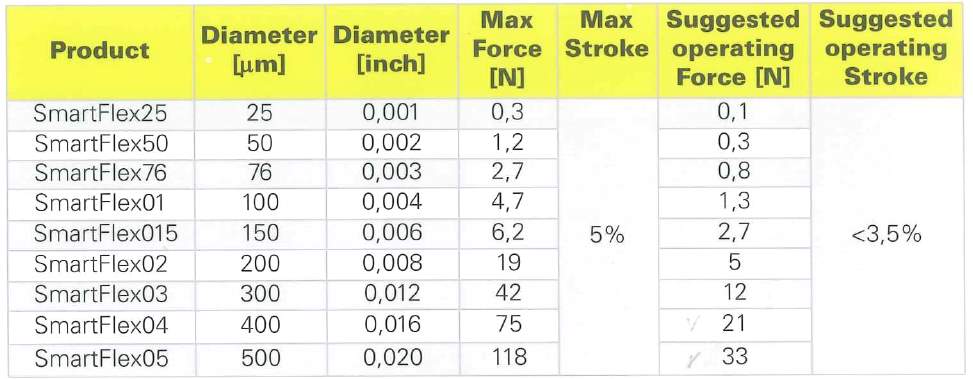
Figure 7: Standard wire diameters and their corresponding values [17]
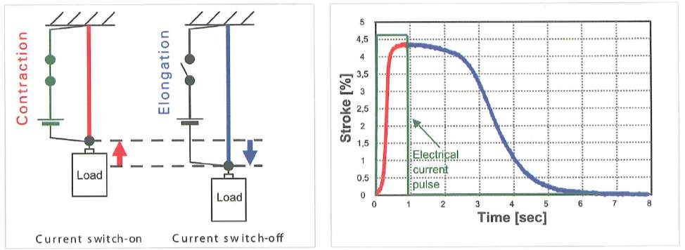
Figure 8: Typical electrical actuation, time vs stroke [18]
In Figure 8, the left picture illustrates the SMA wire contraction and elongation when a current is supplied and cut-off by producing an actuation. The right Figure shows a graph between time and stroke, which explains that when the current is supplied to SMA wire it contracts within a short period of time, and when the current supply is cut off, the wire takes a longer time to cool down.
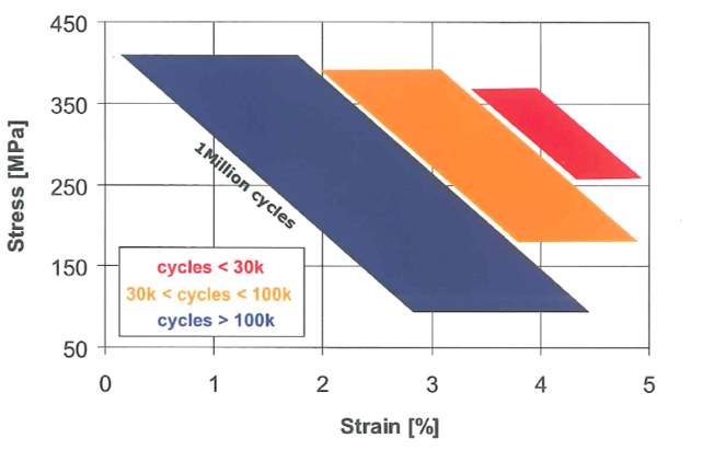
Figure 9: Life cycle behavior under stress-strain [19]
Figure 9 shows the fatigue behaviour under stress-strain. When the values fall in the blue area then the estimated life cycle of the wire is greater than 100000 cycles: in most cases this is considered as a safe design. When the values are in the orange area this means the life cycle of the wire would be between 30000 and 100000 cycles: this condition is considered only when the other properties such as space, wire length etc. dominate over the life span of the wire. Finally, when the values are in the red area, this means the life expectancy performance is less than 30000 cycles: this is not recommended for a SMA-driven product.
2.1.6 SMA wire calculation formulae
The following formulas are very useful in the selection of SMA wire dimensions when utilized in different geometries. In this project, SMA wire is used in two different geometries:
- V-Shape geometry
- U-Shape geometry
In all three cases if the Force (N) and Stroke (mm) are known, then the minimum diameter of the wire can be determined by the following formulas.
For a higher number of life cycles, it is recommended to keep the strain within 4%, as is shown in Figure 9.
Wire calculations for U-shape geometry
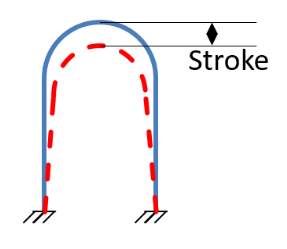
Figure 10: SMA wire in U-shape geometry
The minimum wire length needed (L):
| L=2l mm |
Where,
l – Stroke (mm)
– Strain
Minimum diameter of the wire (d):
| d=4F2πmm |
Where,
F – Force (N)
– Stress (MPa)
Wire calculations for V-Shape geometry
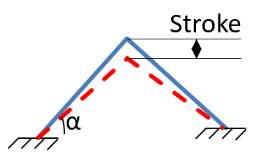
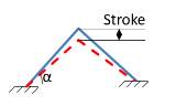
Figure 11: SMA wire in V-shape geometry
The minimum wire length needed (L):
| L=2lsinα mm |
Where,
l – Stroke (mm)
– Strain
α – Angle between SMA wire and horizontal
Minimum diameter of the wire (d):
| d=4F2πsinαmm |
Where,
F – Force (N)
– Stress (MPa)
α – Angle between SMA wire and horizontal
2.2 Plastic parts fabrication
Plastics are one of the most commonly used materials in industry because of their properties including malleability, durability and cost effectiveness. Fabrication of plastic parts includes design, manufacture, and assembly of the parts by various methods available in the market [20]. Not all plastic materials satisfy the functionality of the project, so the materials, functionality, and quantity of the required parts determine the fabrication method.
During development of this project, the first prototype was realized by producing the parts inhouse using a 3D printer. Later parts were produced by using a CNC machine at a customer location. The CNC produced parts helped to get precise values under laboratory conditions. Once the parts are finalized to use under real conditions, then the injections moulding process is used to mass produce the parts. Each fabrication process is briefly described below.
2.2.1 3D Printing Technology
3D printing of plastic parts is a widely-used fabrication process that was used during the concept stage of the project. 3D printers use the technique of additive manufacture. “Additive refers to the successive addition of thin layers between 16 to 180 microns or more to create an object” [21]. Almost all 3D printers work based on additive methods to construct complex products. The material used in 3D printers may vary but they follow three steps to achieve the final product. The printing of the product starts from a CAD sketch, then this data is sent to the 3D printer in the supporting format. After this the printer analyses the CAD data and prints the product by layer by layer by using printing material. This can be plastic, liquid, powder filaments, or sheets of paper [22].
Working principle of 3D Printers
3D printers work in three steps,
Pre-processing: CAD file is prepared with desired features using CAD software or with a 3D scanner and saved in a supporting format (.stl) file format. The file is then sent to a 3D printer.
Production: In this step, a material that satisfies the functionality of the desired product is chosen and after all desired settings are completed, the machine starts printing the part by first heating the thermoplastics to a semiliquid state and then printing layer by layer.
Post-Processing: After the part is printed, it requires fine finishing done by skilled workers. The printed part is cleaned using special chemicals and water in a safe environment.
The material that is chosen for the project determines the printing method. The 3D printer that is used in this project uses FDM technology.
Fused Deposition Modelling (FDM) Technology
In the 1980s, Scott Crump, founder of Stratasys Ltd., first developed and implemented the Fused Deposition Modelling (FDM) technology. This inspired various companies to adopt and develop FDM technology. This technology is mostly used by individuals because of its affordable cost. “This process works by material being melted and extruded through a nozzle to 3D print a cross section of an object each layer at a time, the bed lowers for each new layer and this process repeats until the object is completed” [23]. The quality of the 3D printed part depends on the thickness of the layer. To achieve complex shapes two or more print heads are used in some 3D printers.
Advantages:
- Clean and user friendly
- Supports mechanically and environmentally stable thermoplastics
- Complex geometries and cavities can be achieved
2.2.2 CNC Machining
Even though 3D printers are more useful to produce parts in small quantities and for functional tests at the initial design stage, these parts are not accurate in fit and functionality. When the accuracy of fit and functionality plays a major role, then using CNC machining is the best option for small quantities of parts.
Working
CNC refers to computer numerical controlled machining. In this the CAD design converts into numbers, “these numbers are used as coordinates and the CNC machine uses these coordinates to control the movement of the cutter which creates the shapes as required” [24]. The movement of the machine is controlled on the X, Y and Z axes to machine the material in 3 directions.
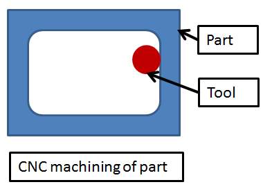
Figure 12: Tool feeding the part in CNC machine
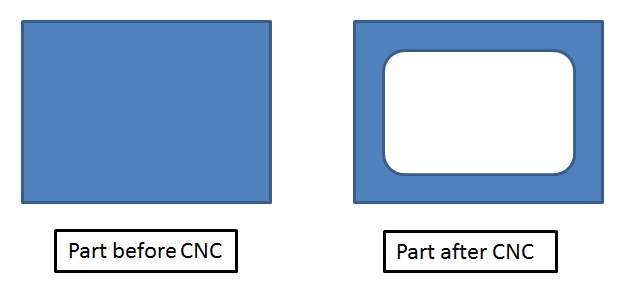
Figure 12 illustrates the typical feeding of a tool in the CNC machine. The tool uses coordinates to cut the part into a desired shape. It can produce sharp corners for outer dimensions, but inside the corners are produced with a minimum radius that is equal to the radius of the tool. Figure 13 is an example of how the part looked before and after machining.
Advantages over injection molding [25]:
- CNC machining allows for 85% of the form, fit, and function testing of injection molded parts without having to produce injection mould tooling.
- Greatest flexibility for design changes
- Greatest cost efficiency for smaller quantities
- No parting lines, ejector marks, or flash
- No draft angles required
- Closest tolerances possible
2.2.3 Injection Molding
Injection molding is one of the most commonly used fabrication methods for plastic components. It is best suited for mass production of plastic parts with repeatability of accuracy achievable.
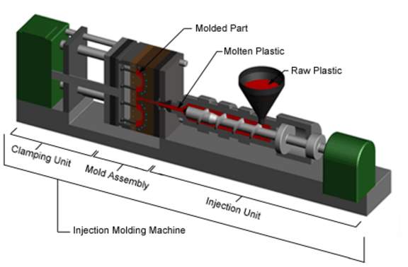
Figure 14: Injection Molding Machine [26]
Working
“Injection molding is the process of heating plastic resin pellets and forcing the melted plastic into a mold cavity. Once the plastic has cooled, the part is released and then the process begins all over again” [27]. Injection molded machines contain three major parts as shown in Figure 14,
- Injection unit
- Mold
- Clamping unit
Plastic pallets in the hopper feed through the barrel into the injection unit. Inside the barrel the screw transport the pallets forward. Heater bands wrap around the barrel to warm the plastic pallets. As the pallets are moved forward by the screw, they gradually melt and are entirely molten by the time they reach the front of the barrel. Once enough molten plastic is in front of the screw, it rams forward like a plunger in a syringe. The screw then injects the molten plastic in the mold cavity image. After the plastic solidifies, the mold opens and the part is ejected. Then the mold is closed and the process repeats [28].
Advantages [29]:
- Complex shapes achieved at affordable cost
- Many parts can be created with same mold at same time
- Tolerance Repeatability and high production rates
- Requires less finishing work and less labour
- Extra material can be reused, hence virtually no waste
2.2.4 Selection of plastic part materials
Proper material selection is critical in prototyping and in low volume part production. The mechanical properties, moldability characteristics, and cost of the material should be considered.
Plastic material selection starts by considering the functional requirements of the application.
The below properties need to be considered when selecting plastics [30]:
- Mechanical loads
- Operating environment
- Needs for transparency
- Compatibility with adhesives and/or surface
- Friction and wear requirements
- Flammability characteristics
3 Actuator Design and Development
The main aim of this actuator is to produce a rotational movement mechanism that can reach and maintain multi stable positions of the rotatable mirror in the HUD by using SMA wire.
3.1 Head Up Display
HUDs were initially used in avionics for military purposes. Now the automotive industry has adopted HUD technology. “With increasing traffic congestion and information density, it is becoming increasingly important that the information needed by the driver and critical to the driving situations is ideally prepared and displayed” [31]. The technological advancements and help of advanced satellite systems has allowed HUDs to become more reliable and safer, by proving the user with a view of both the real world and the overlaid information projected onto the display surface for pleasant driving [32].
A car driver has to constantly adjust their eyes when shifting from viewing the road to monitoring instruments and vice versa. The use of a HUD that projects the instrument information reduces the need for this adjustment and makes it possible to more quickly comprehend the information [33].
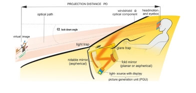
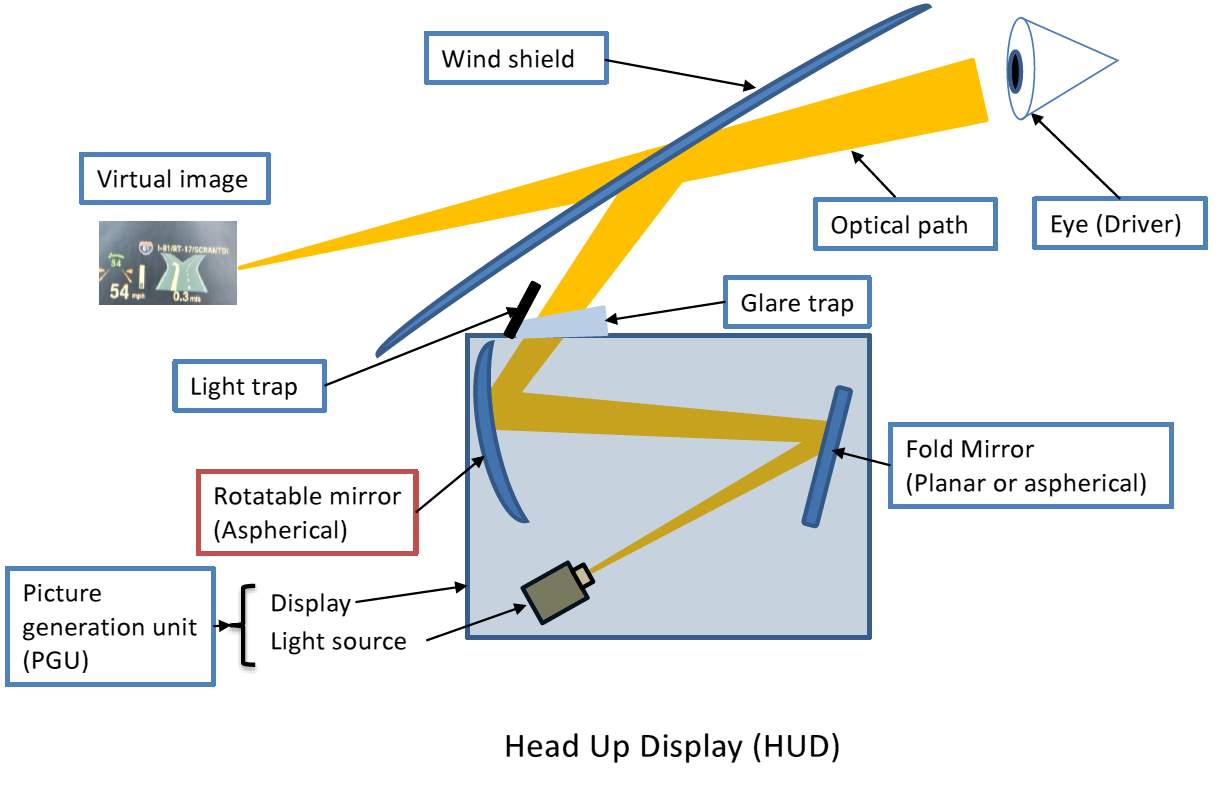
Figure 15: Schematic representation of a HUD [34]
A typical working principle of a HUD is shown in Figure 15. The information (pictures, text) is emitted from a light source called a picture generation unit (PGU). This light is then projected to the fold mirror. The fold mirror helps to align the ghost image to the main reflection. After the light is reflected from fold mirror, the light hits and reflects from the rotating mirror and projects directly on to the wind shield in front of the driver’s eyes.
The height of the image is adjusted by rotating the rotatable mirror. In a conventional method, the rotatable mirror is rotated using a stepper motor. In this project, the SMA-driven rotary actuator is used in place of a stepper motor to achieve customer requested angular positions. The following section explains the development of the rotary actuator.
3.2 Evolution of Design
The evolutions of design stated from studying and understanding the initial inputs from the customer.
Initial inputs:
- The device must be able to produce unidirectional motion
- Total angle to be rotated is 3.52˚
- The image height position must be adjusted by 20 steps with each step being 0.176˚
Table 1: Angles corresponding to mirror position
| Step | 1 | 2 | 3 | 4 | 5 | 6 | 7 | 8 | 9 | 10 |
| Tilt angle (˚) | -1.760 | -1.584 | -1.408 | -1.232 | -1.056 | -0.880 | -0.704 | -0.528 | -0.352 | -0.176 |
| Step | 11 | 12 | 13 | 14 | 15 | 16 | 17 | 18 | 19 | 20 |
| Tilt angle (˚) | 0.176 | 0.352 | 0.528 | 0.704 | 0.880 | 1.056 | 1.232 | 1.408 | 1.584 | 1.760 |
The mechanism should first reach zero position and after reaching zero position it must perform ± 10 degrees on each side with an incremental value of 0.176˚. Table 1 shows the values of mirror tilt angle, corresponding to the steps.
Initial concept:
After studying various possibilities and trying them in sketch and in CAD, the first approach was with a worm gear mechanism. As this mechanism can transmit unidirectional motion, it was the best option to test for initial inputs.
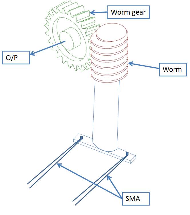
The above shown Figure 17 is a schematic of a controlling mechanism with worm gear and two SMA wires. When any one of the SMA wires is activated, then the worm rotates the worm gear that is attached to the mirror and this motion is unidirectional, which means the mirror will be in locked at a certain position even though it undergoes vibrations. Even though this is efficient in producing unidirectional motion, this mechanism occupies more space and requires more power to achieve the desired motion with a loss of efficiency.
In a conventional method, the HUD mirror is controlled by a stepper motor. The worm gear mechanism is occupying more space than a stepper motor so this is dropped and alternative mechanisms are investigated considering the below factors.
- The design must be cost effective
- Easy to manufacture
- Fewer losses in transmission
- Must satisfy multi-stable condition
- It should be compact
3.2.1 Initial Design
By considering the drawbacks from concept 1, a new design was developed to satisfy the initial requirements. The initial design was developed with a combination of different diameter wheels and three SMA wires. The mechanism is explained below.
To achieve multiple stable positions, the mechanism works in two simultaneous actuations:
- Rotation
- Braking
The mechanism is controlled by 3 SMA wires. Two wires are used to produce a rotational motion and one wire is used for a brake release mechanism. A Hall sensor is used to detect the angle. The Initial design is intentded to achieve the mechanism without considering the overall dimensions.
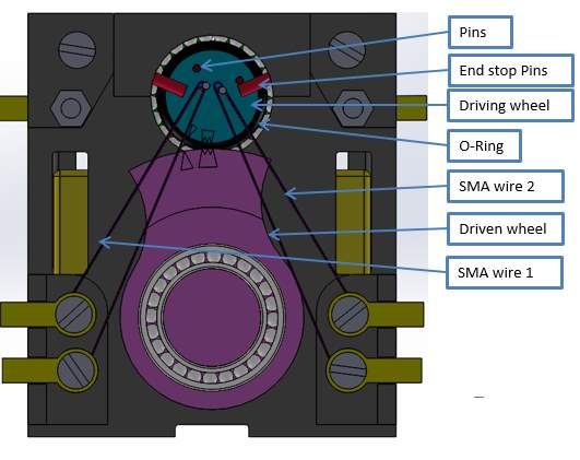
Two SMA wires are attached to an eccentric pin on the small wheel symmetrically in a V-Shape configuration as shown in Figure 18. On activating a wire, the driving (small) wheel is rotated through small angles and this movement is transmitted to the driven (big) wheel though friction. An O-ring is used between the driving and driven wheels as a frictional material. This O-ring facilitates ease of assembly and manufacture. Because of the big and small diameter combinations of the wheels, the rotational movement is enhanced by changing the wheel ratio.
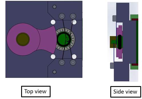
Figure 17: Rotational motion mechanism in initial design
The rotational mechanism can produce a total angle of 3.52˚ with the following configurations:
- The diameter of the driving wheel = 35 mm
- The diameter of the driven wheel = 7.5 mm
- Total angle in smaller wheel (driving) = 16.42°
- Total angle in bigger wheeln(O/P) = 3.52°
- Minimum angle rotation of smaller wheel = 0.821°
- The transmission ration between the wheels = 4.66:1
The main drawback is that when one SMA wire is activated the other opposes the movement and vice versa. This causes interruptions in the rotation.
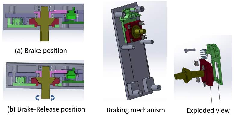
Figure 18: Braking mechanism in initial design
Figure 20 shows a detailed view of braking mechanism. The braking mechanism works in a sequence of steps. Initially the mechanism is under braking conditions (i.e. no rotational motion) by the spring force, shown in Figure 19(a). When the SMA wire is activated then the wire pushes the brake stopper against the spring force, for a stroke of 2 mm. The first 1.5 mm supports the brake shoe and then, due to the inclined step, the brake shoe moves down due to the leaf spring force by 0.5 mm along the inclined profile, thus releasing the brake. Now the shaft can be rotated to a desired angle by a rotational mechanism.
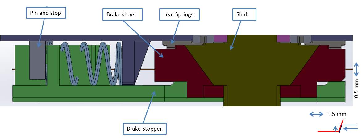
Figure 19: Braking mechanism detailed view
When the desired angle is achieved the SMA wire touches the end stop pin. Then it sends a signal to cut off the power to the SMA wire, which is responsible for brake release. The brake stopper comes back to its original position by spring force. During it coming back to its original position, it lifts the brake shoe by 0.5 mm and this stops the rotation of the shaft due to friction between the shaft and brake shoe.
The brake is capable of stopping a torque of 40 milli-N-m, which is suggested by the customer. But the drawback of this brake is that when the brake stopper moves due to the spring force, then it make a noise. This property means that this does not satisfy customer requirements i.e. a noise free actuator.
To avoid the above two problems, i.e. rotational motion stopping because of wires acting one against each other and the noise in the brake mechanism, a final design has been developed and this is detailed in the following section.
3.2.2 Final Actuator Design
During the initial design development, the customer changed the requirements of the actuator and came up with new set of inputs as follows.
New inputs:
- The device must be able to produce unidirectional motion;
- The mirror must rotate to a total angle of 9.8°;
- After the device is activated the mirror must rotate from parking position to zero position (i.e. 8° from parking position);
- After the mirror reaches the zero position it must perform ± 10 steps each direction with an incremental value of 0.18˚;
- The device must be compact (30mm x 40 mm x 15 mm) as it should occupy less space than existing stepper motor (refer Figure 20);
- The device must consume less power;
- The mechanism must run smoothly with less noise, and if possible no noise.
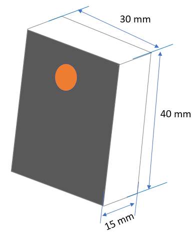
Figure 20: Customer specified dimensions
The final design also works with the same basic principle as the initial design, but here diriment configuration is used as described below:
- Two SMA wires attached in a U-shape configuration to produce rotation;
- One SMA wire is used in V-shape configuration to release the brake, but here the brake is applied in a radial direction.
The two mechanisms are explained in detail in the following.
Rotational motion:
The total angle to be achieved as per the new inputs is higher compared to the initial design, and therefore to build the mechanism in the final design is more challenging. Here two SMA wires are assembled as two eccentric pins in a U-shape configuration individually as shown in Figure 21. Four eccentric pins are attached to the driving (small) wheel (ref Figure 21). First two pins (used for wire) with a diameter of 0.6 mm are inserted into a driving wheel at an eccentric distance of 1 mm each. The other two pins with a diameter of 0.6 mm are inserted in the driving wheel at an eccentric distance of 2.6 mm each. These pins are used for ends top during calibration.
When one of the SMA wires is activated then the wheel rotates in the same direction as the wire movement; this driving wheel then rotates the driven wheel, which is connected to the rotating mirror. The idea is to achieve a bigger stroke that leads to a larger angle of rotation in a smaller space (the final product dimensions are shown in section 3.4).
A Hall sensor is aligned axially exactly above the driving wheel, which then senses the angle of rotation made by driving wheel. A detailed working description of a Hall sensor is explained in section 3.3. Theoretically the Hall sensor that is used in this project can sense at least an angle of 0.0219⁰ (see data sheet in the appendix), but practically the Hall sensor can detect a minimum of 0.5⁰ angles by considering losses (this value is suggested by the Electronic Department in ASG). So, the mechanism is designed to produce a minimum of 0.54⁰ by taking losses (such as measuring, assembling, environment etc.) into consideration.
 |
 |
| Figure 21: Final actuator rotational mechanism | Figure 22: Final actuator rotational mechanism
made from CNC produced parts |
Figure 21 refers to a CAD model that shows a mechanism with combination of small and big diameter wheels with a transmission ratio of 3:1. A prototype made from CNC produced parts is shown in Figure 22.
From the customer inputs, the mechanism must produce a total angle of 9.8⁰ to reach the mirror in all desired positions. This means the driving wheel should able to reach an angle of 29.4⁰. But for calibration purposes (suggested by the Electronic Department) it must perform an additional 2⁰ angle to reach the end stop pins i.e. a total angle of 31.4⁰.
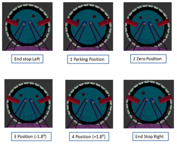
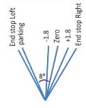 The final positions to be achieved are shown in Figure 23 in a simple schematic form. Initially, when the car is in an off condition, the mirror is located at the parking position. The actuator is activated when the user starts the car. Once the actuator activated, first it calibrates by reaching end stops (i.e. total angle) then it moves to zero position (i.e. it rotates 8.33⁰ from end stop left). After reaching the zero position, the mirror can be adjusted ± 10 steps with each step of 0.18⁰. The user will adjust the height of the image by adjusting the mirror position.
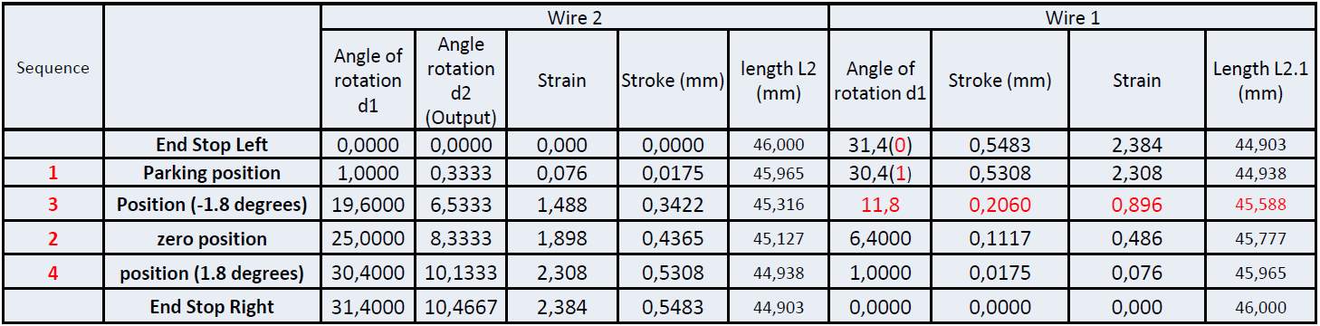
To reach the mechanism in all positions suitable wire dimensions should be calculated and implemented in the mechanism. The wire lengths corresponding to the angular position are shown Table 3 which gives more detail of the values, and the pin orientation at various positions is shown in Figure 24. The values in the table are valid only when the system is balanced with two wires. If the balancing is undertaken with the friction between the wheels then one side of wire action is sufficient to produce the rotation.
Table 2: Wire lengths corresponding to the mirror angular positions
The wire length, and corresponding current and voltage values are calculated as follows:
SMA wire calculations:
- Diameter of the driving wheel
d1= 9 mm
- Diameter of the driven wheel
d2= 27 mm
- Transmission ratio =
d2:
d1= 3:1
- Total angle required by customer (output) = 9.8⁰
- Total angle in driving wheel
α2=
9.8*3=29.4 (+ 2⁰ to reach end stops) = 31.4⁰
- Minimum angle of rotation in driven wheel = 0.18⁰
- Minimum angle of rotation in driving wheel = 0.54⁰
- Total angle in driven wheel during calibration = 10.466⁰
- Total length of the wire can be accommodated
L1= 46 mm
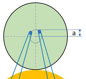
 Eccentric distance (a) = 1 mm (ref fig. 25)
|
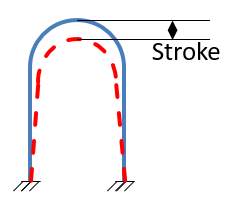
Figure 27: SMA wire in U-shape configuration |
Stroke=2πaα2360=2*π*1*31.4360= 0.5483 mm (ref fig 26)
Strain =2lL1= 2*0.548346= 0.0238 mm
Length of the wire after activation (L2):
L2=L1-L1= 46-0.0238*46=44.903 mm
Minimum wire diameter of the wire for cycles > 100 k
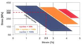
From the Figure 27 the values of stress and strain are,
Strain = 2.5 % = 0.025 and Stress = 330 MPa
Wire cross-section area A=F 2mm2
Where,
F – Force (N)
– Stress (MPa)
Diameter d=4F2π mm
(Area=π4 d2)
Diameter d=4*102*π*330= 0.14 mm ≈ 150 microns
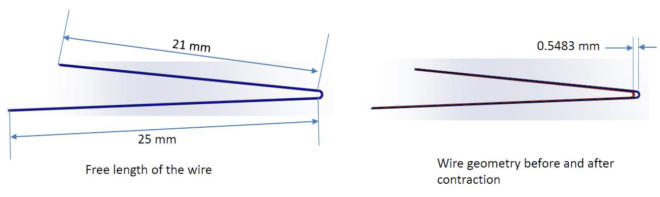
Figure 28: Wire length before and after activation
Figure 28 represents SMA wires in a U-shape configuration before and after activation. The current and voltage values to achieve the required stroke are calculated as follows:
Current and Voltage Calculations:
Length of the wire
L1= 46 mm
Diameter of the wire
D1= 0.15 mm
Current (I) = 0.6 A
Resistivity () = 0.001 mm (constant)
Cross section area of the wire (A)=π*D124=0.0177 mm2
Resistance (R)=*L1A=0.001*460.0177= 2.60
Voltage(V)=I*R= 2.6*0.6 =1.56 V
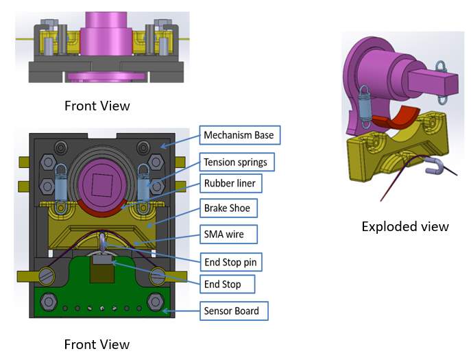
Figure 29: Final actuator brake release mechanism views
Figure 30: Final actuator brake release
mechanism made from CNC produced parts
Even though the braking mechanism in the initial design is able to produce a satisfactory braking force, the mechanism failed to satisfy the no noise condition. Here in the final design the brake is applied radially on to the shaft. Figure 29 shows different views of the brake release mechanism. Initially the mechanism is in a braking condition. Two tension springs are attached to a brake shoe that would create sufficient force (refer to section 3.5) to hold the shaft against rotation. A friction material is used on the brake shoe to reduce the spring force and to increase braking capacity. One SMA wire is attached in a V-shape configuration to the pin, which is inserted in the brake (refer to SMA wire calculations for all the wire dimensions). When the mirror needs to be rotated, then the SMA wire is activated to make a stroke of 0.6 mm thus releasing the brake. When the brake moves 0.6 mm along with the pin, the pin touches the end stop in the Hall sensor PCB at the end of the stroke. Once it touches the end stop, the signal is processed and activates the other SMA wires that are responsible for rotation. Once the mirror rotates to a desired angle then the power is cut off to the brake SMA. When the power is cut off to the SMA, then the brake pulls back to its original position by a spring force. This leads to the shaft rotation stopping and the brake holding it until the SMA is activated again.
The brake force and the required SMA wire dimensions are calculated as follows:
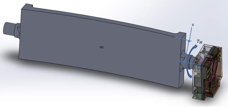
Figure 31: Final actuator assembled to mirror
Torque (
TM)= 40 mill-N-m (Given)
Distance (
x) = 25 mm
Force F=TMx
Where,
TM-Torque moment (milli-Nm)
x-distance from axis to the extreme point(mm)
F=40 milli-N-m0.025 m= 1600 milli-N=1.6 N
Mass of the mirrorm:m=Fag= 40 mill kg m2s20.025 m x 9.8 ms2 =163 grams
The spring force is chosen such a way that the force can stop the shaft against 40 milli-N-m.
SMA wire calculations:
- Stroke required to release the brake (l) = 0.6 mm
- Force needed to overcome spring force (F) = 10 N
- Total spring force (Fs) = 9.378 N (standard spring with 10 newtons is chosen ref springs in section 3.5 for explanation)
- Angle which the wire makes with the horizontal when it is attached in V- shape configuration (α)= 30⁰ (ref fig. 32)
- Strain value from the graph () = 2.5% = 0.025
 Minimum wire length when the strain is 0.025
Minimum wire length needed L:
L=2lsinα mm
Where,
l – Stroke (mm)
– Strain
α – Angle between SMA wire and horizontal
L=2*0.6*sin(30⁰)0.025=24 mm
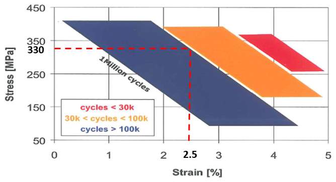
Figure 33: Stress and strain values from lifecycles graph
The stress and strain values are derived from the lifecycle graph as shown in Figure 33.
Strain () = 2.5 % = 0.025
Stress () = 330 MPa
Minimum wire diameter of the wire for cycles > 100 k
Wire cross-section area (A)=F 2sinα mm2
Diameter d=4F2πsinα ( Area=π4 d2)
Diameter d=4*102*π*330*0.5=0.20 mm=200 microns
Current and Voltage Calculations:
Length of the wire
L1= 24 mm
Diameter of the wire
D1= 0.2 mm
Resistivity () = 0.001 mm (constant)
Current (I) = 0.8 A
Cross section area of the wire A=πD124= 0.0314 mm2Resistance R=LA=0.001*240.0314=0.76
Voltage V=IR=0.76*0.8=0.61 V(Practically the brake is working at 1.5 V)
3.3 Hall Sensor Assembly
Hall sensors are used to measure an angle of rotation (or movement). The Hall sensor assembly contains a sensor and a magnet. The sensor is placed in static conditions above or to the side of the magnet with a specified air gap and the magnet is attached to the rotating (or moving) part (in this project it is attached to driving wheel). When the driving wheel rotates along with the magnet, the sensor senses the change in magnetic flux and sends this measurement to the electronics for calibration. The functionality of the mechanism is controlled by electronics. Below Figure 34 shows the assembly of a Hall sensor in the rotating actuator. An air gap of 0.8 mm is maintained as shown in Figure 34. A brief description of sensor and magnet is below.
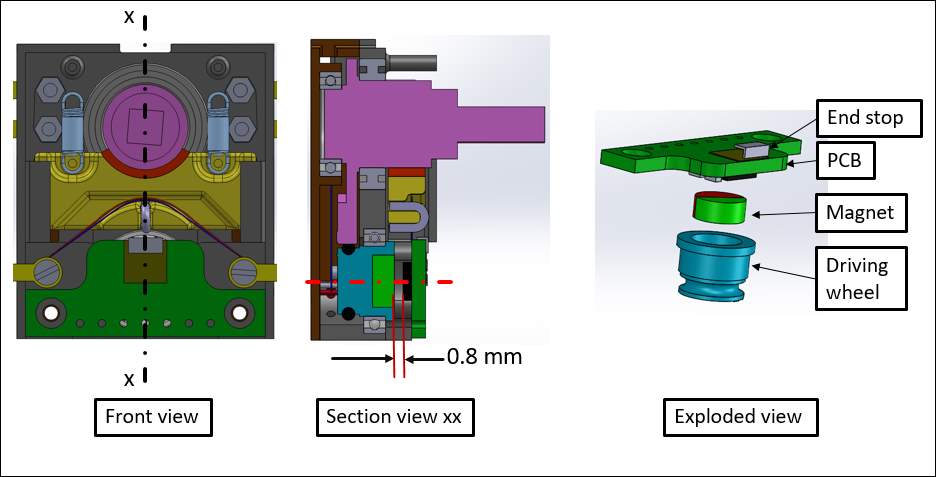
Figure 34: Hall sensor assembly in actuator
Hall sensor
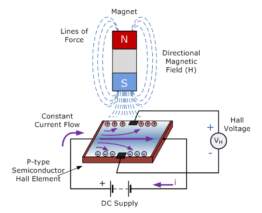 The workings of the Hall sensor can be explained as when a current is passed through a thin piece of rectangular p-type semiconductor material (ref Figure 34) then charged particles flow in a straight path. “When this device is exposed to a magnetic field in which the magnetic flux is perpendicular to the flow of charged particles then the magnetic flux exerts a force (Lorentz force) on the semiconductor material which deflects the charge carriers, electrons and holes either side of the semiconductor slab” [36]. The voltage difference between these planes is called Hall voltage. “The effect of generating a measurable voltage by using a magnetic field is called the Hall effect” [37].
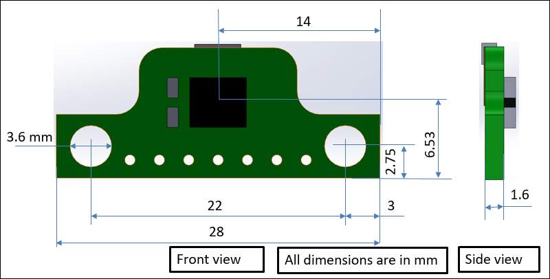
Figure 36: Hall sensor position in PCB
The Hall sensor that is used in this project is a product of the company AMS AG with the part number AS5048B. The Hall sensor placement and PCB dimensions are shown in Figure 36. From the data sheet (ref data sheet in the appendix) the Hall sensor has the following properties [38]:
- The Hall sensor AS5048B is a 14-bit angular position sensor, with a maximum system accuracy of 0.0217⁰: this is estimated as 0.5⁰ under working conditions [39]
- The operating voltages are either 3.3 V or 5 V
- The temperatures can range from -40⁰C up to +150⁰C.
These excellent operating properties of the sensor make it ideal for rotational angle sensing in harsh industrial and automotive environments.
Magnet
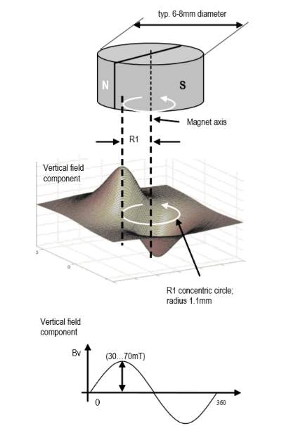 Choosing a proper magnet provides accurate results. According to the Hall sensor AS5048 manufacturing company AMS AG, “the sensor works with magnet having typical diameter 6-8 mm, height ≥ 2.5 mm and the magnetic flux
BZat a given distance, along a concentric circle with a radius of 0.1 mm should be in the range of ±30 to ±70mT” [40] (refer data sheet in appendix).
Figure 37 shows a schematic from the data sheet. The allowable axis to axis between magnet and the centre of the IC is within the displacement radius (Rd) of 0.25 mm and the magnet can be placed above or below to the IC by maintaining an airgap range of 0.5 to 2.5 mm for the magnet with material sintered NdFeB and dimensions of 6mm x 3mm [42] (refer data sheet for more details about NdFeB magnet).
The above Hall sensor is suggested by the Electronic Department and it provided support in terms of the electronics and software to control the device, including the Hall sensor.
3.4 Bill of materials (BOM)
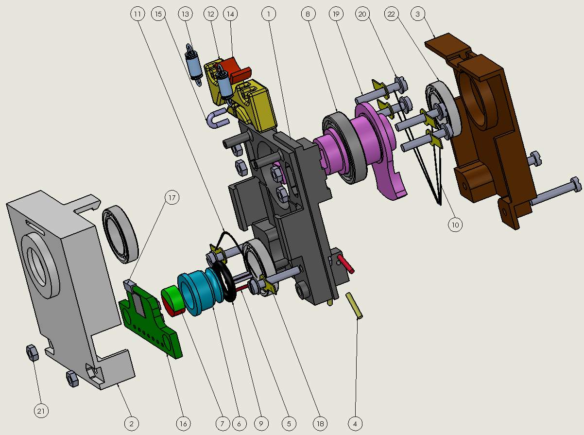
Figure 38: Final actuator exploded view
The above Figure shows an exploded view of the final actuator, which shows a list of parts utilized in this project to produce the customer specified results.
In Table 5 a complete parts list is shown along with the used quantity. The materials for each part that are not standard are discussed in detail in the section relating to parts dimension and material selection (Section 3.5)
Table 5: Bill of materials final actuator
| No | Part Name | Qty | No | Part Name | Qty |
| 1
2 3 4 5 6 7 8 9 10 11 |
Mechanism Base
Base Housing Top Cover Pin_ End stop rotation Pin_ SMA wire rotation Driving Wheel Hall sensor_ Magnet Bearing_10x15x3 O-Ring_6x1.5 SMA wire_ Rotation SMA wire_ Brake release |
1
1 1 4 4 1 1 1 1 2 1 |
12
13 14 15 16 17 18 19 20 21 22 |
Brake shoe
Tension Spring Brake Shoe Liner Pin_ Brake Hall sensor End Stop_ Brake Washer_ Crimp Bolt_ M1.6×10 Washer Nut_M1.6 Bearing_BR128 |
1
2 1 1 1 1 6 8 6 8 3 |
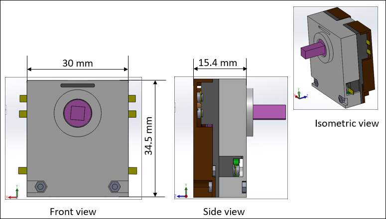
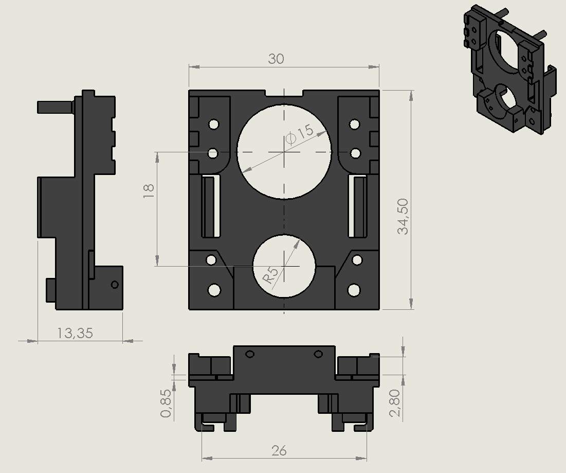
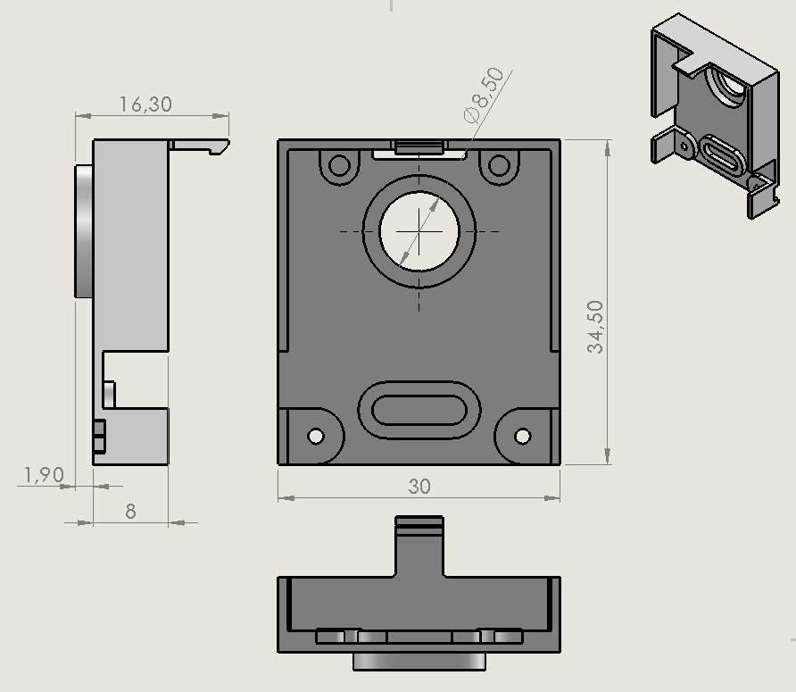
Figure 39: Overall dimensions of final actuator
Figure 39 shows the overall dimensions of the final actuator, from which it is clear that the final dimensions satisfy the customer input dimensions.
Assembling sequence:
A proper assembling sequence reduces time and labour cost. This assembling process was developed for the prototype. The assembly sequence takes place in four major steps as follows (see Figure 40):
- Step 1 Driving wheel assembly preparation
- Step 2 Brake assembly preparation
- Step 3 Driven wheel assembly preparation
- Step 4 Final assembly preparation
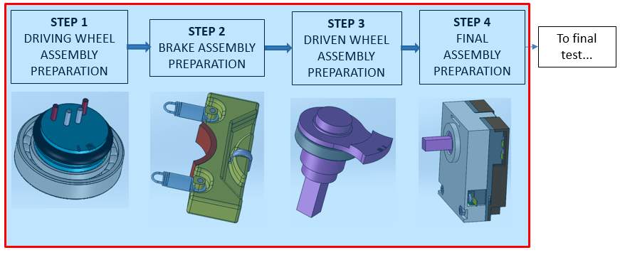
Figure 40: Final actuator major assembling steps
Step 1 Driving wheel assembly preparation:
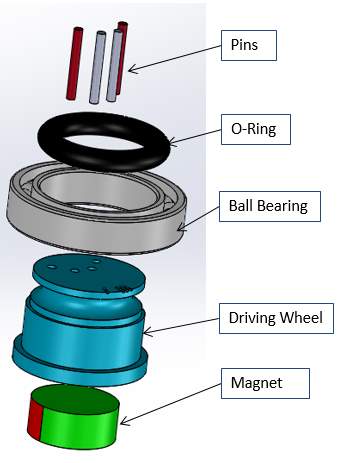
Figure 41: Driving wheel assembly
The assembly takes place as shown in Figure 41. First the ball bearing (refer bearing BR 128 in the appendix for more technical details) is assembled with the driving wheel and then the O-ring in the given position. The four pins and a magnet are inserted into the slots provided in the driving wheel.
Step 2 Brake assembly preparation:
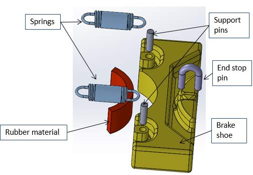
Figure 42 shows a section of the brake assembly. To construct it, first stick the rubber material onto the brake shoe with an adhesive and then insert the support pins and end stop pins in the provided slots then attach the two tension springs. The support pins give strength to the plastic when the springs are under extreme tension.
Step 3 Driven wheel assembly preparation
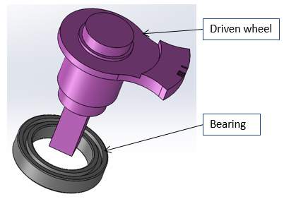
Figure 43: Driven wheel assembly
This is the simplest step in the entire assembly, as the bearing just needs to be assembled with the driven wheel (refer to bearing B6700 in the appendix for more technical details).
Step 4 Final assembly preparation
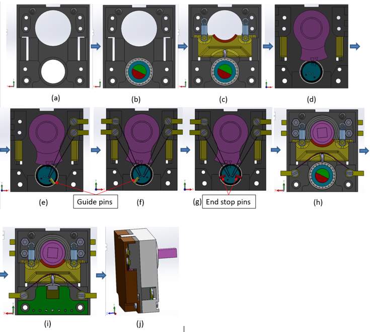
Figure 44: Final assembly sequence
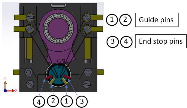
Figure 45 shows pin positions. The guide pins 1 and 2 act as end stops and help to maintain sufficient tension while assembling the wire. Pins 3 and 4 are the end stop pins used during calibration.
Figure 44 gives a final assembling sequence and this is explained as follows:
- Mechanism base
- Fit the driving wheel sub assembly to the mechanism base
- Insert the brake sub assembly into the guide provided in the mechanism base
- Rotate the base to its other side and insert the driven wheel sub-assembly and adjust the wheel to match markings with the driving wheel and then connect the springs (ref c) to the extrusions in the base
- First insert guide pin 1 into the hole provided in the base and run the 150 microns wire over the eccentric pin that is in the driving wheel. Guide pin 1 acts as an end stop and helps to maintain sufficient tension in the wire during assembly. Then fix the wire by sandwiching it between the washers.
- Repeated the procedure as in step e, but with guide pin 2 on the adjacent side as shown in Figure 45.
- After assembling the wire responsible for rotation, now insert the end stop pins. These pins help during calibration.
- Turnaround the device and assemble the 200-micron wire as shown in the Figure and fix it with screws to the base.
- Insert the Hall sensor assembly in the extrusions provided in the mechanical base.
- Finally assemble the housing covers by screwing one side and by snap fitting another side. This housing provides protection to the parts as well as an aesthetic look for the customer.
3.5 Part dimensions and material selection
The mechanism base is the critical part of the entire assembly. As many of parts come in contact with the mechanical base (ref section 3.4), its material should have good chemical and mechanical properties. POM is the material best suited for this purpose as it has good chemical resistane and high tensile strength. Some metal pins are used to strengthen the part where the springs are attached to the mechanical base. Necessary guiding features are provided to accommodate the brake, sensor board, and crimps.
For initial design the mechanical base is produced inhouse by 3D printer and the material used is Verowhite rgd 835. For the final actuator the part is produced in a CNC machine at a supplier and the material used is POM (Polyoxymethylene). POM is used because it has very good impact resistance, good processability, appearance, and dimensional stability.
In the mass production stage POM is used to produce this part because of the above mentioned reasons.
As there is less space, the brake is designed to be applied radially. Small metal pins are used to strengthen the extruded areas where the springs are attached to brake and a metal pin in a U‑shape is attached such a way that it acts as an end stop when the brake moves to its farthest distance (ref Figure 42). As it is in contact with the mechanism base, these two parts should not be made with the same material. At the mass production stage the material PA (Poly acrylate) is used to produce this part. PA has very good temperature resistance and good mechanical properties.
For first prototype the brake shoe is produced inhouse by 3D printer and the material used is Verowhite rgd 835.
For the second prototype the part is produced by CNC machine at the supplier place and the material used is POM (Polyoxymethylene).
Wheels:
|
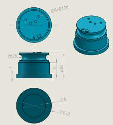
|
Wheels are the most important parts in this actuator. A combination of different diameter wheels are used to achieve the required output speed in less space as it is a small actuator. After the SMA wire is actuated, the driven wheel rotates in the direction of the activated SMA wire, then the driving wheel rotates because of the friction (o ring) between the driven and driving wheels.
As these parts are thinner, play a critical role in transfering motion, and are in contact with bearings, they should have very good mechanical and chemical properties. At a mass production stage these parts are produced by using POM in an injection mold design process. In the driven wheel metal pins are used for strength and to withstand the temperature where it is attached to the SMA wire.
For first prototype both the wheels are produced inhouse by 3D printer and the material used is Verowhite rgd 835.
For the second prototype the parts are produced in CNC machine at the supplier place and the material used is POM (Polyoxymethylene).
Spring force is used for braking the system. Initially the springs are attached with pre-tension and after the mechansm activates then the springs elongate 0.6 mm to release the brake by the force created by the SMA wire. A standard spring from a supplier, Gutekunst Federn, is used in this project. Figure 50 shows the values at various conditions of the spring (see spring data sheet in the appendix for further details).
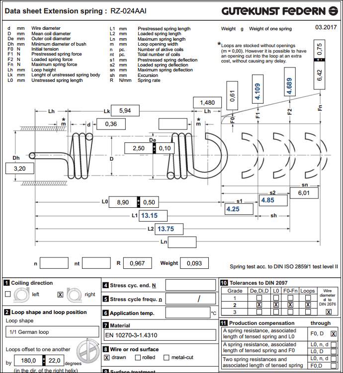
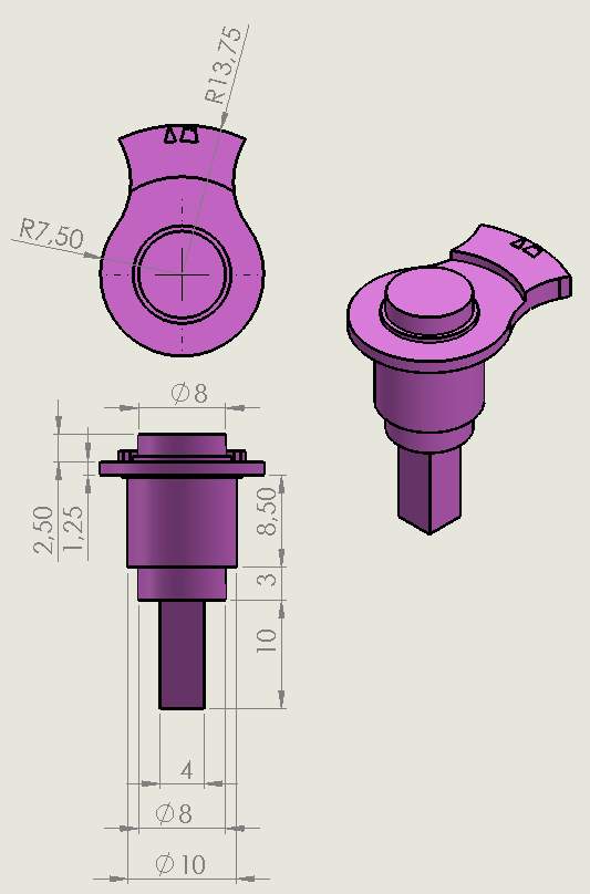
Figure 50: Extension spring dimensions
Where:
Pre stressed spring length L1=13.15 mm assembling condition
Pre stressed spring force total F1=8.218 N (assembling condition)
Loaded spring length L2=13.75 mm (Brake release condition)
Loaded spring force total F2= 9.378 N (Brake release condition)
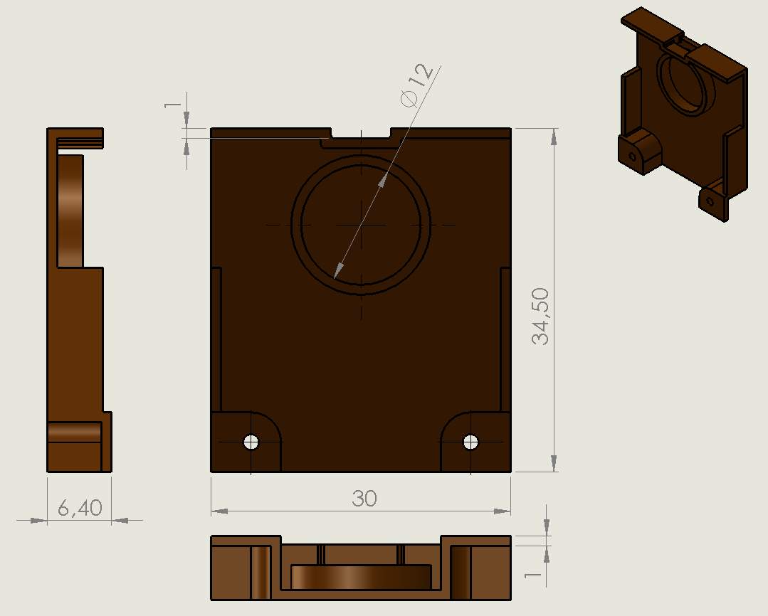
|
|
The housing covers the working parts and gives an asthetic look for the user. The housing contains top and bottom covers as shown in Figures 51 and 52 respectively. Both the covers are attached to the shaft by bearings (ref appendix for BR 128) to reduce and facilitate a smooth motion. In mass production the bearings are replaced with balls to reduce the cost of the part. Because of not having a place for screwing both sides, on one side a snap feature is designed and on the other side screwing as shown in Figure 41 (j). A provision is provided on the top cover for holding the snap from the bottom cover.
The housing bottom cover is designed in such a way that it can facility the holding of the bosses from the base and these bosses support the springs. An emboss is given to hold the sensor board tightly against slipping: this helps to record accurate readings even when subject to vibrations.
For the first prototype the housing covers are produced inhouse by 3D printer and the material used is Verowhite rgd 835. For the second prototype POM is used and it is produced by CNC machine at a customer location. POM is used in the mass production because the ball comes into contact between the covers and the shaft and, because of the snap, the part should also be of a flexible and tough material.
3.6 SMA fastening techniques
Connecting the SMA wire to the mechanism is itself a difficult task. Eventhough there are many connection techniques available, in this project three main methods were considered.
3.6.1 Soldering
The first approach to fasten the SMA wire to the system was by soldering. Even though it is a simple solution, there are significant disadvantages. As the SMA wires are easily affected by temperature, when it is connected by soldering the SMA may loose its mechanical properties and deform permanently. Therefore this method of fastening has been avoided.
3.6.2 Crimping using fasteners
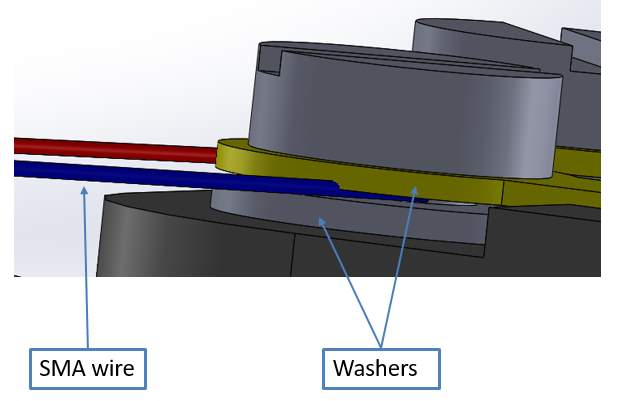
Figure 53: SMA wire crimping with fasteners
In this method any type of closures are used to connect the SMA wire, for example riviting or sandwitching the wire between two washers by tightning the screw.
For the final acutator, the wires are sandwitched between the two washers when the wires are in pre-tension as shown in Figure 53.
The advantage of this method is that there is no need to design extra crimps: standard wachers availabe in the market can be readily used depending on the SMA wire diameter.
The disadvantage of this method is that the wire become loose after a period of operation, hence it loses its accuracy. To overcome this failure the wires should be tightened after every certain period of operations.
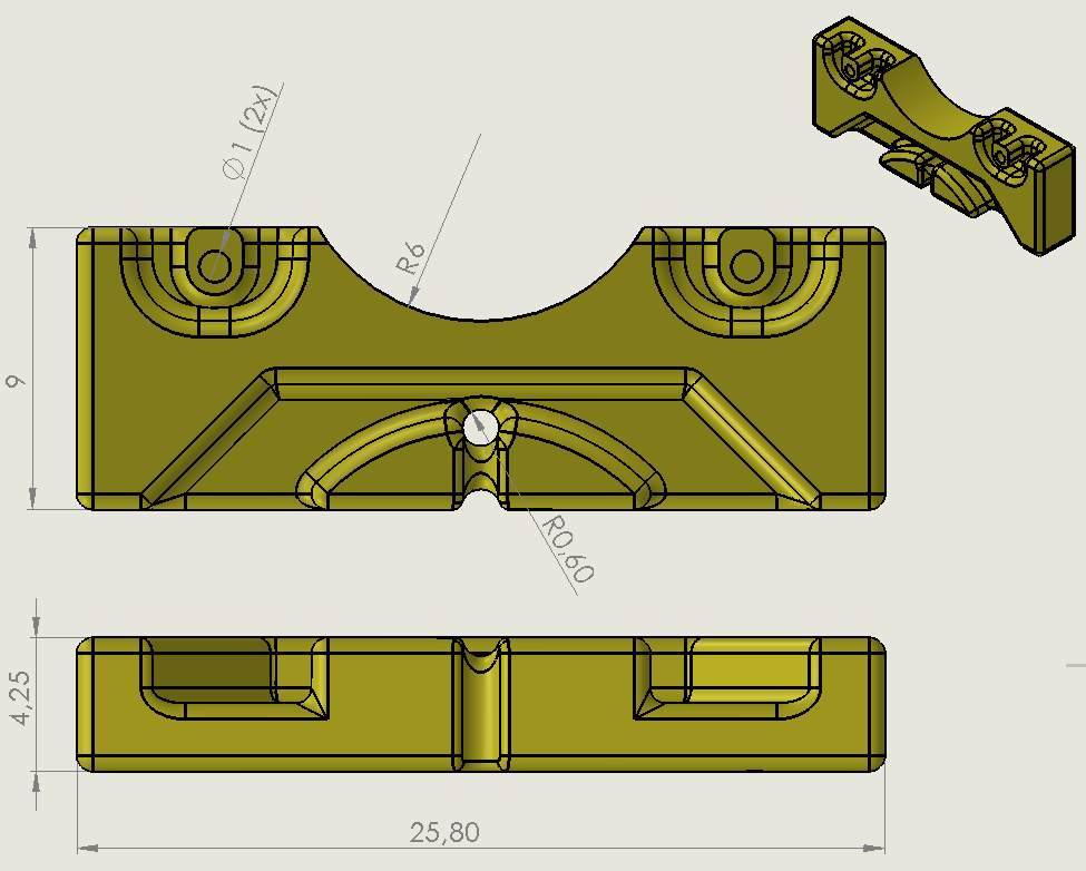
3.6.3 Fastening with specially designed crimps
This is the most reliable crimping technique and gives accurate results when the wires are crimped correctly. With this method, specially designed crimps are used to fix the SMA wires. The material CuSn6 was used to make this crimp. The crimp dimensions vary depending upon the wire diameter and pullforce. The optimum force needs to be found for crimping to hold the wire, otherwise the wire will slip out. For the pullout test, the crimp should hold the wire until 600MPa.
After studying previous test results, which were performed inhouse, the thickness of the crimp was decided as 0.5 mm thick and the material as CuSn6. This dimension of the SMA wire used in both rotational and braking mechanisms does not significantly differ. Eventhough the specially designed crimps do not use this prototype, this information is relevent for the future work (ref Figure 54 and 56 for more details).
For the rotational mechanism, the SMA wire used is from SAES Getters. It was SMArtFlex015 with a crosssection of 150 microns and is capable of producing a force of 10 N at 2.5 % strain.
For the braking mechanism, the SMA wire used was SMArtFlex02 with a crossection of 200 microns and is capable of producing a force of 10N for 2.5% strain. This SMA wire is also a product of SAES Getters.
As the both wires are capable of producing a force of 10 N, the dimensional crimp below is suitable for satisfying all the necessary tests. Window slots are provided to enable more holding force for the crimp, and thus help avoid slipping of the SMA wire.
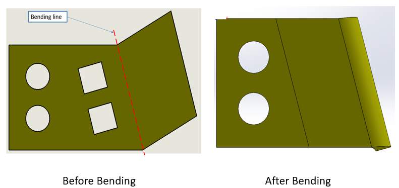
Figure 54 is a drawing of the crimp and the Figure 56 shows CAD data of the crimp before and after the bending, where a wire is placed on to the crimp passing over the windows and then the crimp is bent along the bending line. Figure 55 shows a wire in the crimp, and later these crimps are attached to the mechanism base.
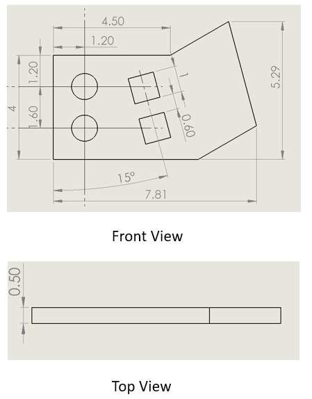
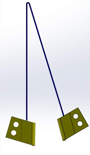 Figure 54: Special crimp dimensions
3.7 Analysis of snap using solid works simulation
The simulation is carried out to find out the theoretically allowable dimensions to design a snap in the housing bottom cover (ref Figure 49). The bottom cover is snapped shut to the top cover at one side instead of using screws, so the type of latch used must be analysed for best results.
The simulation is carried out for two types of materials with the help of solid works simulation. One material is used in house i.e in the Actuator Solutions GmbH to produce the part using 3D printing technology and the other material is used to produce the part at the client location i.e Valeo by using a CNC machine.
The materials are:
- Simulation using material Verowhite RGD 835
- Simulation using material Polyoxymethylene (POM)
The below conditions are common for both the simulation cases:
| Units: | |
| Unit system
Length/Displacement Temperature Angular velocity Pressure/Stress |
SI (MKS)
mm Kelvin Rad/Sec N/ m2 |
| Study properties: | |
| Analysis type
Mesh type Thermal effect Thermal options Zero strain temperature Solver type Large displacement |
Static
Solid mesh on Include temperature loads 298 Kelvin FFEPlus Off |
3.7.1 Simulation using material Verowhite RGD 835
The material verowhite RGD 835 is used in Actuator Solutions GmbH to produce the parts for prototypes using a 3D printer. This 3D printer is from Strasasystems (ref 2.2.1 for explanation).
Table 8: Material properties RGD 835
| Material properties: | |
| Material name:
Model type: Tensile strength: Elastic modulus: Poisson’s ration: Mass density: Shear modulus: |
Verowhite RGD 835
Linear elastic isotropic 60MPa 300 MPa 0.394 1020 Kg /m3 318.9 MPa |
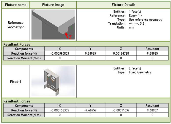
Table 9: Mesh information RGD 835
| Mesh information | |
| Mesher used:
Jacobian points: Element Size: Mesh Quality: Total Nodes: Total Elements: Maximum Aspect Ratio: |
Standard mesh
4 Points 0.854987 mm High 44461 25303 10.27 |
3.7.2 Simulation using material POM
POM was used to produce the parts using CNC machining at the customer location.
Table 10: Material properties POM
| Material properties: | |
| Material name:
Model type: Tensile strength: Elastic modulus: Poisson’s ration: Mass density: Shear modulus: |
POM Acetal
Linear elastic isotropic 71.5 MPa 260 MPa 0.3859 1390 Kg /m3 932.8 MPa |
Loads and Fixtures
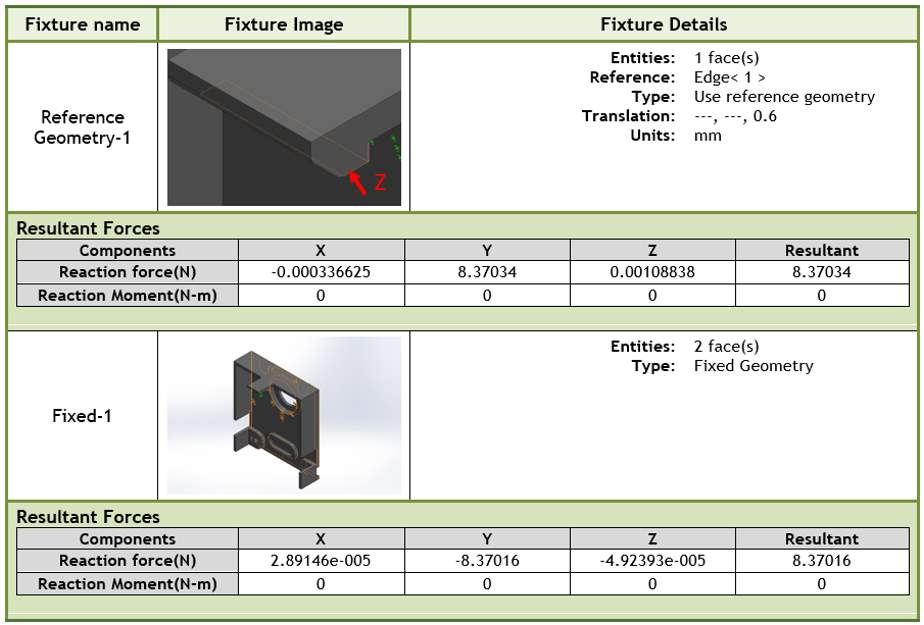
Table 11: Mesh information POM
| Mesh information | |
| Mesher used:
Jacobian points: Element Size: Mesh Quality: Total Nodes: Total Elements: Maximum Aspect Ratio: |
Standard mesh
4 Points 0.854987 mm High 44461 25303 10.27 |
Reaction Forces
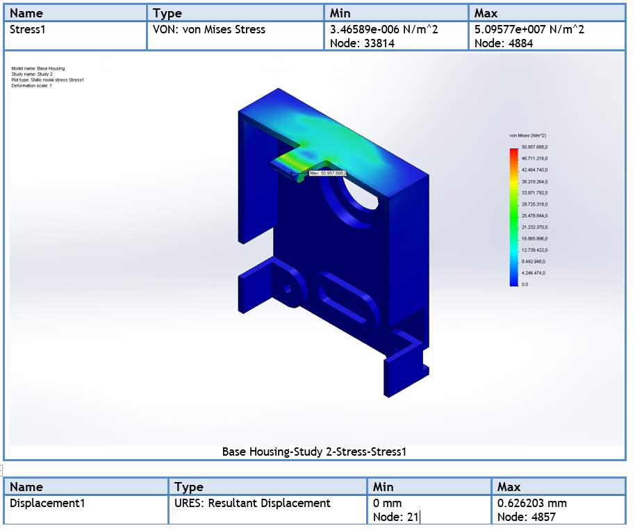
Study Results
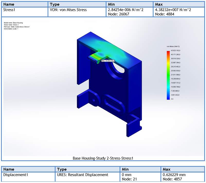
3.7.3 Analysis results conclusion
The design is to be considered safe if the von Mises Stress is less than the yield strength of the material. After studying the above analysis results, it is clear that the considered dimensions of the part for both materials are under the safe limits.
Simulation results for the material RGD 835:
- Yield strength = 60 MPa
- Von mises stress = 50.95 MPa
Simulation results for the material POM:
- Yield strength = 71.5 MPa
- von Mises stress = 43.8 MPa
4 Future work and Conclusion
Satisfactory results were achieved in the second prototype under laboratory conditions. From these results further development needs to be undertaken to obtain more accurate results when operated in real world conditions.
In the first prototype the braking mechanism was able to produce more braking force when compared to the second prototype. This is because in the first prototype the contact area is in a cone shape and thus the area of contact between shaft and brake shoe is large, whereas in the second prototype the brake is applied radially and this affords less contact between shaft and brake shoe. In the second prototype using two springs caused problems in balancing the brake shoe when it is pulled by a SMA wire.
Future work will involve combining the best results from both concepts i.e the braking mechanism from the first prototype and the rotational mechanism from the second prototype. DFMEA also needs to be undertaken within the future work and a decision made on which parts to be kept at the mass production stage. The range of the mirror rotation and accuracy of the angle measured will increase by introducing latest Hall sensors.
5 References
[1] Actuator Solutions. (2015). About us. Retrieved 03.14.2017, from Actuator Solutions: http://www.actuatorsolutions.de/
[2]Actuator Solutions. (2015). Our Advantages. Retrieved 04.06.2017, from Actuator Solutions: http://www.actuatorsolutions.de/company/
[3]Actuator Solutions. (2015). Scope of Applications. Retrieved 04.06.2017, from Actuator Solutions: http://www.actuatorsolutions.de/
[4]Actuator Solutions. (2015). The Mission. Retrieved 04.06.2017, from Actuator Solutions: http://www.actuatorsolutions.de/company/
[5]Segers, D., Hurtado, I., Dorikens-Vanpraet, L., & Van Humbeeck, J. (1995, January). Positron Dopplerbroadening Measurements in Cu-Al-Ni Based Shape Memory Alloys. Journal de Physicque, 5, C1-163 – C1-169. doi:10.1051/jp4:1995119
[6]Tinialloy. (2003). TiNi Alloy Company: Shape Memory Alloy Microdevices: Introduction to shape memory alloys. Retrieved 04.05.2017, from Tinialloy: http://www.tinialloy.com/pdf/introductiontosma.pdf
[7]Morgan, N. B. (2004, July 25). Material Science and Engineering: A Son science Direct. Medical shape memory alloy applications-the market and its products, 378(1-2), 16-23. Retrieved 04.06.2017, from http://www.sciencedirect.com/science/article/pii/S0921509303015132
[8]Parikshith, K. K., & Dimitris, C. L. (2008). Shape Memory Alloys: Modeling and Engineering Applications: Shape memory alloy – A Brief History. (C. L. Dimitris, Ed.) New York, NY, USA: Springer Science+Business Media, LLC. Retrieved 01.06.2017
[9]Harsha, S. P. (2014, 02 12). Vibration control: Shape memory alloy. Roorkee, India. Retrieved 04.06.2017, from http://nptel.ac.in/courses/112107087/34
[10-15]Parikshith, K. K., & Dimitris, C. L. (2008). Shape memory alloys: Modeling and Engineering applicaitons: Phenology of phase transformation in shape memory alloys. (C. L. Dimitris, Ed.) New York, NY, USA: Springer Science+Business Media, LLC. Retrieved 01.12.2017
[16]Parikshith, K. K., & Dimitris, C. L. (2008). Shape memroy alloys: Modeling and engineering applications: Shape memory effect. (C. L. Dimitris, Ed.) New York: Springer Science+Business Media, LLC. Retrieved 01.13.2017
[17-19]Saesgetters. (2009). SmartFlex: 100% quality controlled shape memroy alloy wire for micro actuators. Retrieved 03.16.2017, from Saesgetters: https://www.saesgetters.com/sites/default/files/SmartFlex%20Wire%20&%20Spring%20datasheets_0.pdf
[20-22]3D printing from scratch. (2017). Types of 3D printers or 3D printing technologies overview. Retrieved 03.25.2017, from 3D printing from scratch: http://3dprintingfromscratch.com/common/types-of-3d-printers-or-3d-printing-technologies-overview/
[23]Stratasys. (2017). FDM Technology: 3D print durable parts with real thermoplastic. Retrieved 03.26.2017, from Stratasys: http://www.stratasys.com/3d-printers/technologies/fdm-technology
[24]Bay Plastics Ltd. (2014). CNC Machining: CNC Milling, CNC Routing & CNC Cutting. Retrieved 03.20.2017, from Bayplastics: http://www.bayplastics.co.uk/cncmachining.htm
[25]Precisoon engineered products. (2016). Connecticut plastics: Machining v. Molding. Retrieved 03.19.2017, from pepctplastics: http://www.pepctplastics.com/resources/machining-vs-molding/
[26]Custompart. (2017). Injection Molding. Retrieved 03.13.2017, from Custompart.net: http://www.custompartnet.com/wu/InjectionMolding
[27-29]icomold. (2016). About Plastic Injection Molding. Retrieved 04.06.2017, from IcoMold: https://icomold.com/knowledge-base/
[30]Cubell Plastics. (2017). Research Materials. Retrieved 04.06.2017, from Cubell Plastics: https://www.curbellplastics.com/Research-Solutions/Materials
[31-34]Continental automotive. (2017). Head-up Displays – Eying safety and comfort at all times. Retrieved 04.06.2017, from Continental-automotive: http://www.continental-automotive.com/www/automotive_de_en/themes/passenger_cars/interior/instrumentation_displays/pi_head_up_en.html
[35-37]Electronics Tutorials. (2016). Hall Effect Sensor. Retrieved 4.6.2017, from Electronics-Tutorials: http://www.electronics-tutorials.ws/electromagnetism/hall-effect.html
[38-42]AMS. (2016, November 16). AS5048B High Resolution Position Sensor: 14-bit rotary position sensor with digital angle (interface) and PWM output, 1-09. Retrieved 01.14.2017, from AMS: http://ams.com/eng/Products/Magnetic-Position-Sensors/Angle-Position-On-Axis/AS5048B
6 Appendix
A. Injection moulding material properties
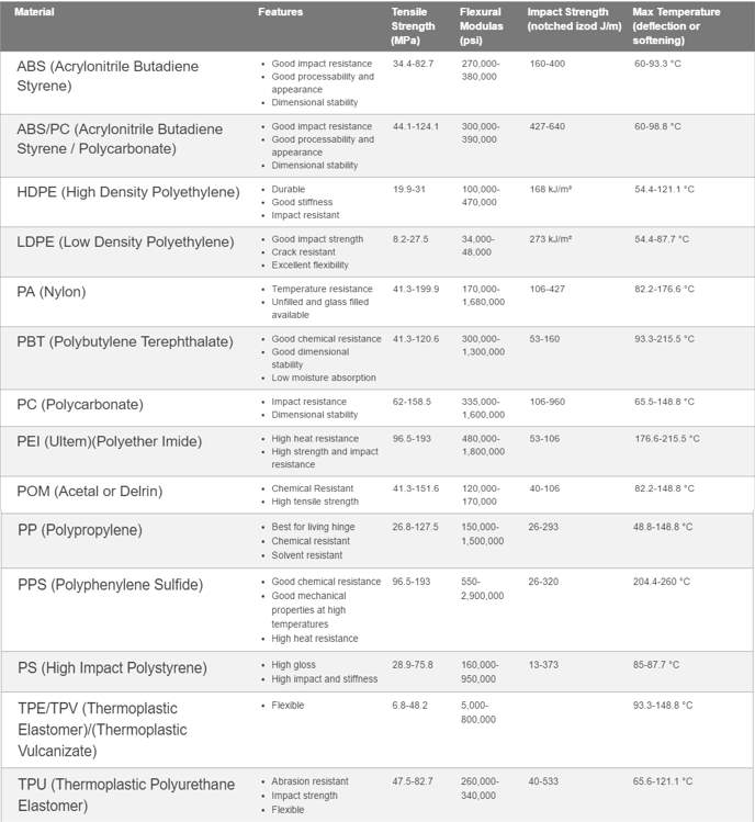
B. Magnet Datasheet
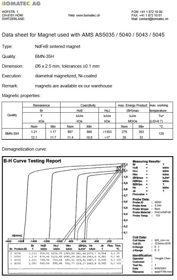
C. 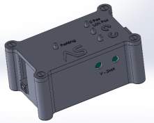 Control Box
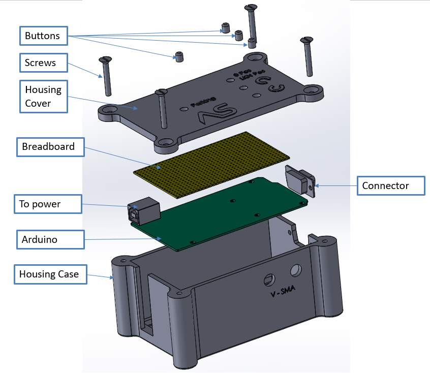
The control box contains all necessary electronic parts to allow the mechanism to be controlled. Controlling software is embedded in the Arduino board and connected to the buttons. There are four buttons indicating parking, 0 position, left and right movement. When the power is off, the mechanism places the mirror in the parking position and when the power is on the mirror rotates and stays at 0-position. From here the user can adjust the height of the output image by pressing the left and right buttons, which turns the rotating mirror. There is also the provision to connect the wires from the actuator through a connector.
D. Actuator Assembled with HUD Mirror
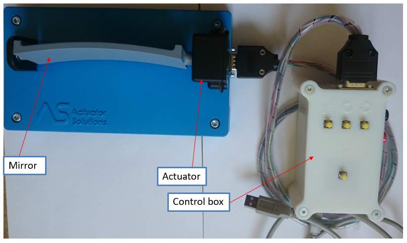
The above Figure shows a prototype build in Actuator Solutions with a model mirror.
E. Data sheet verowhite plus RGD 835
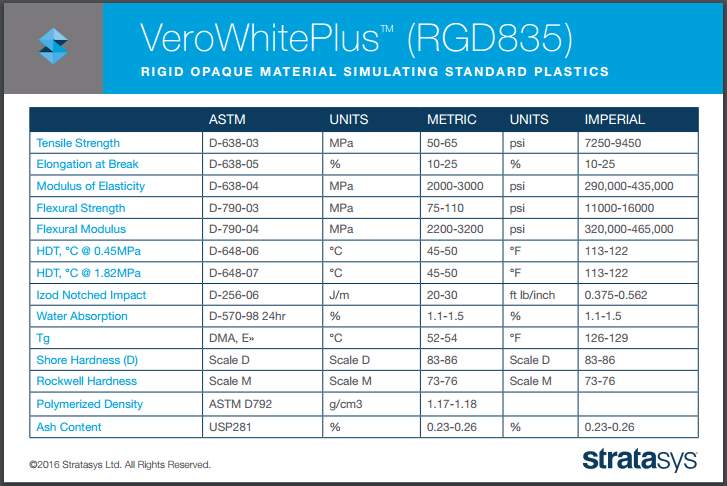
F. Hall sensor AS5048 data sheet
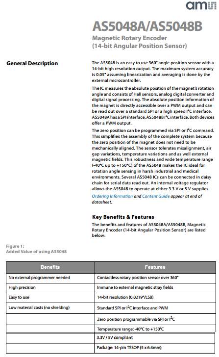
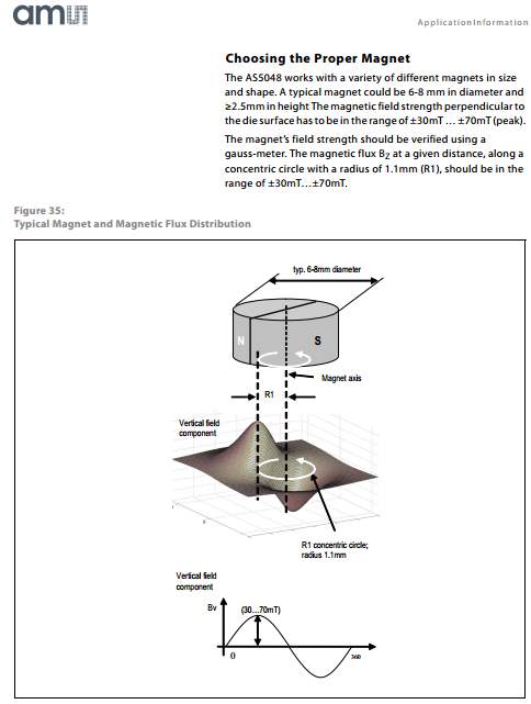
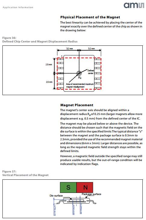
G. Bearing B6700 data sheet
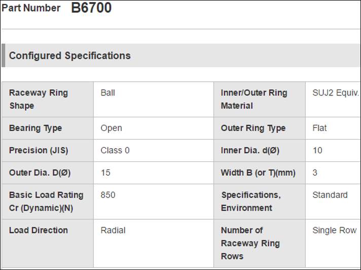
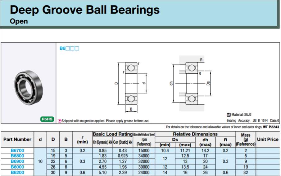
H. Bearing BR 128 data sheet
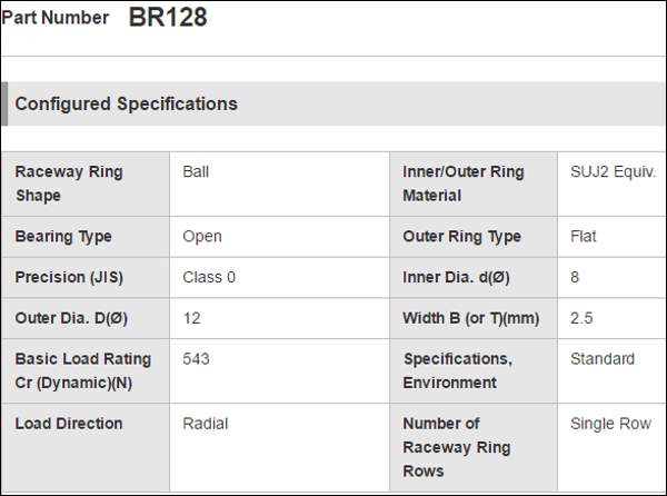
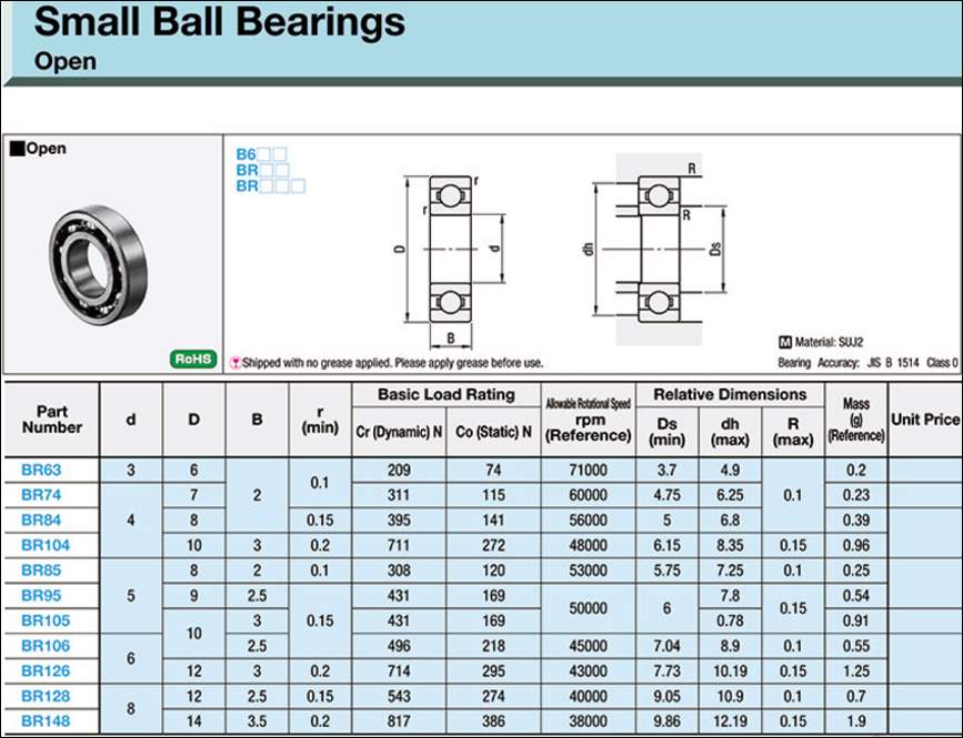
I. Spring data sheet
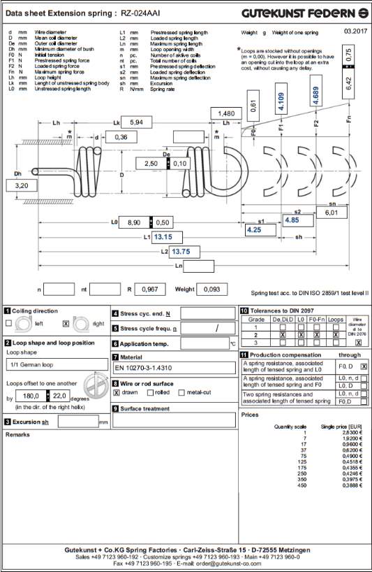
Cite This Work
To export a reference to this article please select a referencing stye below:
Related Services
View all


Related Content
All TagsContent relating to: "Mechanics"
Mechanics is the area that focuses on motion, and how different forces can produce motion. When an object has forced applied to it, the original position of the object will change.
Related Articles

DMCA / Removal Request
If you are the original writer of this dissertation and no longer wish to have your work published on the UKDiss.com website then please: