Reliability Analysis of a Substation and How Faults Impact Reliability
Info: 9977 words (40 pages) Dissertation
Published: 23rd Dec 2021
Tagged: EngineeringEnergy
Abstract
The key focus of this master thesis is to study the reliability analysis of a substation and how faults impact its reliability, security and stability. The changing environment in the energy sector creates a need for substation system operators to be able to robustly evaluate the impact that possible measures have on the dependability of supply of their networks. The substation is considered an important part of the electrical network system, and this has gained significant focus for electrical power system planners and operators to improve reliability. I shall present the types of faults and analyse their effect on the substation system. I shall also present substation reliability methods and determine their significance. The results of this analysis shall provide critical input to evaluating the reliability of the substation and the effects of substation failures.
Keywords: Electrical power systems, power systems quality, power system stability, power systems protection, electrical faults, fault analysis, substation reliability.
“Negative results are just what I want. They’re just as valuable to me as positive results. I can never find the thing that does the job best until I find the ones that don’t.” (Thomas Edison)
Chapter 1 – Introduction
Reliability of power systems is a hot topic in the industry. There are several components that represent the electrical power system. The substation is the main study of this thesis. There have been various studies based on reliability analysis in the power system but only several of these studies concentrate on electrical power substations.
There are two aspects for power system reliability analysis which are system adequacy and system security. System adequacy mainly focuses on the connectivity of the system while system security considers the protection devices and post-fault phenomena.
In this thesis, the reliability study specifies how different faults in a substation can impact the power system adequacy and security. When evaluating these faults and the impact on the substation reliability, it is assumed that the substation is under normal conditions. Once a fault occurs, this thesis will evaluate the reliability results and the consequences of the fault initiated in the substation.
This thesis will take into consideration both system faults and component faults. Maintenance procedures are also taken into consideration as well as the effect of environment and humans on the component repair time. Reliability evaluation methods…
1.1 Background
The primary aim of the electricity supply system is to meet the demands of its customers for electrical energy. It must deliver power to all its customers, reaching every customer with a supply of sufficient strength to meet the peak demand of that particular customer for electric power. The electricity supply must also be reliable, providing an uninterrupted flow of power to the customer and meeting all of his demand for electricity all the time. The supply must also be free of high levels of harmonics and transient electrical disturbances. Another important requirement is the safety of the electricity supply.
Substations, however well designed are not fault free. The level of security intended by the designer is usually based on certain imposed conditions. These conditions are usually referred to as security standards. Such standards vary from utility to utility for economic reasons.
For most interconnected transmission networks upon which a large number of consumers depend on their supply, the security standards are more often than not based on the so-called ‘n minus one (n-1)’ criteria. No loss of supply or unacceptable power quality (voltage or frequency) must occur for the loss any single component. This dictates a level of redundancy in network design. Spare generation, transmission capacity obviously requires additional capital expenditure. Government legislation imposed on electrical utilities, usually demands that they provide for reasonable security of supply. The 1947 UK Electricity Act, for example, calls for ‘A continuous and abundant supply’. In the presently developing privatisation and de-regulation scenario, security standards for main generation and transmission networks are likely to be adhered to.
In most cases, however, substations are designed such that some or all of the consumer supplies can at least be restored within a specified time. Single fault outages of substation equipment are permitted to result in a short duration loss of supply. Obviously a fault outage of a single element, transformer, cable etc. feeding one or more consumers will result in a loss of supply for repair time. Most utilities adopt security standards that depend on the nature and level of the load to be supplied.
Failures within the substation affects availability, quality and extents of the power system. One of the basic roles of reliability studies in electrical power systems is to optimise system failure rates.
Reliability of a substation is difficult to measure. The best ways are through evaluation of the consequences of possible consumer interruptions and component failure. The following steps assist in the implementation of substation reliability and efficiency: –
- Plan the substation to have enough capacity.
- Design the substation to reduce the probability of equipment failure.
- Operate the substation to remain within safe operating margins.
- Be prepared to restore the system quickly, in the event of a supply disruption.
The balance between reliability and costs need to be considered. It is difficult to design a substation with sufficient reserve margin to have a perfectly reliable system. For example, some types of common-mode failures due to causes such as storms involve so many facilities that it would be financially impossible to design a substation to tolerate them. This is why reliability analysis can be beneficial.
The purpose of this research study is to describe the method of reliability analysis of power system substations and explore methods for improving the system.This analysis also studies the criticality and sensitivities of the components of the substation for unremitting improvement. It shall contribute in identifying the components of the substation that need more consideration for better improvement against faults.
This research shall discuss in greater detail cost-effective, intelligent and higher performance methods against substation failures. New technologies are becoming more prominent in the energy World as substation owners aim to keep up with the demand for electricity. This results in substation owners pursuing new technologies and solutions to enhance the flexibility of its substations and improve its capacity and reliability.
1.2 Aims and Scope
The substation components and devices are vulnerable to faults like short circuit conditions and can result in severe economic losses which in-turn reduces the reliability. Extensive studies and developments on substation installations and the protection schemes have resulted in the continual improvement in the prevention of damage to switchgear and interruptions to the supply.
Short circuit studies and hence fault analysis is very important for the power system studies since they provide data such as voltages and currents during and after the various types of faults which are necessary in designing substation protection schemes. An effective protection scheme shall basically consist of protective relays, fuses, intelligent electronic devices and switchgears such as circuit breakers, surge arresters etc.
There are so many books, articles and technical reports that give detailed accounts of power system reliability methods. In this literature review I will discuss my interpretation of these methods and summarise the best approach to which methods are best for analysing substation reliability.
When evaluating reliability, it is necessary to have complete understanding of fault implications on the system. No amount of probability theory can evade this important function. It is apparent therefore that probability studies are only a tool that enables us engineers to transform knowledge of the system into a prediction of its likely future behaviour. After this understanding can a model be derived, and the most appropriate evaluation practice selected.
1.3 Thesis Outline
This thesis is organized as follows.
Chapter 1 is general introduction to the project, including the background description, project description and objectives.
Chapter 2 is a general introduction to basic reliability concepts and the different types of substation faults. Failure probability, failure frequency and other reliability concepts are explained.
Chapter 3 discusses substation structures such as one and a half breaker arrangement, double busbar arrangement and mesh arrangement where I carried out software modelling to determine the effects of the different types of faults impact them. This chapter also discusses reliability analysis methods such as reliability centred maintenance (RCM).
Chapter 4 gives a review of what has been accomplished in this thesis, discusses the conclusions from this research and makes some conclusions.
Chapter 2 – Reliability Concepts and Substation Faults
2.1 Reliability Concepts
The key function of the electrical power system is to deliver energy to the end consumer adequately and efficiently. It is essential for the power system to be efficient, safe and secure. If not, any faults or losses within the system can cause huge economic losses and safety issues. Therefore, reliability analysis and reliability methods of the power system is of fundamental importance.
Electrical power systems are increasing in size and complexity in all parts of the generation, transmission, distribution and load systems. With the advancement in substation control and operation technologies, the possible scenarios of failure events and causes also become more complex. The reliability, security and quality of power systems are significantly affected by faults.
2.1.1 Reliability Subdivision
The term reliability has changed over the decades. Until the 1960’s reliability was defined as ‘the probability that an item will perform a required function under the stated conditions for a stated period of time’.
The present definition for reliability as stated in ISO 8402 is ‘the ability of an item to perform a required function, under given environmental and operational conditions and for a stated period of time’.
The term ‘item’ is used here to denote any component, sub-system, or system that can be considered as an entity. In our case a component, protection, substation etc. A required function may be a single function or a combination of functions that is necessary to provide a specific service. All technical items (component, sub-system, systems) are designed to perform one or more (required) functions. Some of these functions are active and some functions are passive.
The power system can be separated into two categories: system adequacy and system security. System adequacy is the ability of the electric system to supply the aggregate electrical demand and energy requirements of customers at all times, taking into account scheduled and reasonably expected unscheduled outages of system elements.
System security is the ability of the electric system to withstand sudden disturbances such as electric short circuits or unanticipated loss of system elements.
The reliability analysis of a substation can be divided into three aspects: improper design, improper installation and deterioration in service. In this thesis, I will determine the reliability of the substation in all these areas when a fault occurs.
2.1.2 Basic Concepts
Reliability can be measured in a number of ways depending on the particular situation, for example:
- Mean time to failure (MTTF)
- Number of failures per time per unit (failure rate)
- The probability that the item does not fail in a time interval (survival probability)
- The probability that the item is able to function at time.
The basic concepts of substation reliability analysis can be defined below, as detailed in a research paper written by Fengli Wang [1]. [1] Fengli Wang, “Reliability Evaluation of Substations Subject to Protection Failures” Delft University of Technology, July 2012, pp. 6-7.
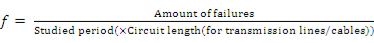
Failure Frequency (f):
The Failure frequency refers to the number of failures that may happen during a time period. In this study, the dimension of the failure frequency is failures per year.
2 – 1
Mean Time to Failure (MTTF):
The average time it takes to the occurrence of a component or system failure measured from t=0.
Mean Time to Repair (MTTR):
The average time it takes to identify the location of a failure and to repair that failure.
Then the relationship between the failure frequency and the Mean Time to Failure is:
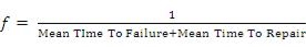
2 – 2
In above equation, the unit for Mean Time to Failure is years.
Reliability (R(t)):
Reliability refers to the probability that a component experiences no failure during a time period, given that it was good at time zero.
Failure Probability (Q(t)):
The failure probability is the probability that, under stated conditions, the system or component fails within a stated period. It is identical to unreliability, which is denoted as F(t)
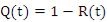
2 – 3
Availability (A):
Availability is the probability that the component is normal at an arbitrary time t, given that it was good at time zero.
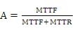
2 – 4
Unavailability (U):
Unavailability is the probability that the component is down at an arbitrary time t and unable to operate if called upon.
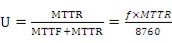
2 – 5
In the formula above, 8760 in the right part is the total hours of one year, because MTTR is measured in hours.
According to the definition of availability and unavailability:
 2 – 6
2 – 6
The concept pairs of reliability/failure probability and availability/unavailability are more or less the same. The difference between them is whether the maintenance of the component is considered. If a healthy component is under maintenance to be checked for its quality, then it is reliable, but unavailable.
2.2 Substation Faults
A substation has many components such as step-up transformers, step-down transformers, disconnecting switches, circuit breakers, voltage transformers current transformers, and surge arrestors. Initiating fault is when a fault develops on any of these components that will contribute to a protection system respond.
An initiating fault can be caused by several different reasons. When there are switching actions or lightning strokes in the substation, some of the components may be subject to transient effects, which could cause an insulation fault. The fault occurring under this situation is called a transient fault. After the fault occurs, the protection system will send the responding circuit breakers a tripping signal to isolate the faulted part. After a short period, the fault path will be cleared and the circuit breakers will perform an auto-reclosure.
Besides, for the components that have been into operation for a long time, the aging of the insulating material can lead to a breakdown mechanism. When a component experiences a breakdown in the last period of its life cycle, this fault is called the permanent fault. Unlike the transient fault, after the tripping of the circuit breakers to isolate the faulted part, there will be no auto-reclosure. After the corrective maintenance or the replacement of the component, the operator on site will put the faulted part back into operation again. [1] Fengli Wang, “Reliability Evaluation of Substations Subject to Protection Failures” Delft University of Technology, July 2012, p 14.
Environmental factors can also contribute to component faults such as lightning strikes, storms, ice and snow, birds and rodents. These environmental conditions interrupt the power supply and damage electrical switchgear. This form of fault can be defined as a semi-transient fault.
A fault in electrical components is essentially the defect in its electrical circuit which makes current path directed from its intended path. It is normally caused due to breaking of conductors or from failure of insulation that these faults occur. There are a number of other reasons for faults which include mechanical failure, accidents, excessive internal and external stresses. The impedance of the electrical path in the fault is low and the fault currents are comparatively large.
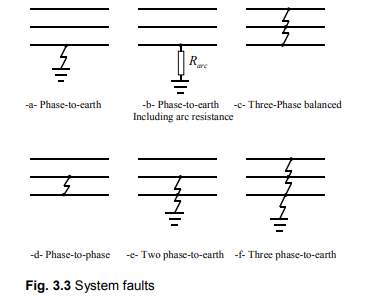
These faults can be three-phase in practice which entails three phases in a symmetrical presence or can be asymmetrical where typically only one or two phases are involved. Faults are also initiated from short-circuits to earth or between live conductors or can be produced by defective conductors in one or more phases. Occasionally, simultaneous faults can develop from short-circuit and defective conductor faults, further identified as open-circuit faults.
Three-phase balanced faults can be determined by adopting an equivalent single-phase circuit. Through asymmetrical three-phase faults, the application of symmetrical factors assist in decreasing the intricacy of calculations as transmission and distribution lines and components are fundamentally symmetrical, even though the fault can be asymmetrical.
When a fault is initiated within a substation, the voltages of the three phases turn out to be unbalanced. As a result of high fault current, the switchgear and components in the substation may fail. The power flow is then diverted in the direction of the fault which will disrupt the supply.
Faults are unable to be completely removed in a substation, but their presence can be reduced by improving substation design, quality of the equipment, contingency plans, and maintenance strategies.
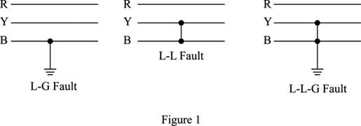
AC faults can either be single line to ground fault, double line to ground fault, three phase fault, that may occur in the substation due to unbalance in current and voltage, over voltages, reversal of power, power swings, under frequency, temperature rise and instability.
In fault analysis it is very important how faults are distributed in the various sections of a power system. There are many statistics on that which are available in the literature and internet as well. However, typically, the distribution is as follows: [3] Power system faults, Wroclaw University of Technology, 2011, Jan Izykowski, p 9
Switchgear 30%
Transformer 24%
Cables 20%
Miscellaneous 16%
Control equipment 6%
CTs and VTs 4%
Note – Overhead line fault percentage is discarded for this purposes as I am only interested in faults within the substation.
Line to ground fault – 85%
Line to line fault – 8%
Line to line to ground fault – 5%
Line to line to line fault – 2% or less
Substation fault analysis is essential to produce detailed guidance and overview for the selection of switchgear, setting of relays and stability of system operation. A substation is not stationary but fluctuates through operation and planning. Therefore, fault studies are required to be routinely carried out by utility engineers.
2.2.1 Fault levels (short-circuits)
The substation is designed and anticipated to supply loads in an efficient and secure way. An important aspect in substation design is to consider adequate control of short circuits. If short circuit faults are not controlled, then this can result in avoidable loss of electricity supply along with all of its numerous consequences. Substations are deigned to be as fault-free as possible and this is achieved through suitable equipment selection and design, network layout, appropriate installation and regular maintenance. However, with all these strategies in place, faults continuously take place on substations at all transmission and distribution voltage levels.
When a fault takes place on a substation, there are several effects which can occur, such as:
1. At the fault location, arcing and burning can occur.
2. Short-circuit current flows from the various sources to the fault location.
3. All components carrying the short-circuit currents are subject to high thermal and mechanical stress, which varies as a function of the current squared (I²) and the duration of this current flow.
4. System voltage drops in proportion to the magnitude of the short-circuit current. The most severe voltage drops clearly occur at the ‘nodes’ on the network closest to the fault location. The voltage could reach almost zero for a 3-phase fault with minimal fault impedance. However, all parts of the power system are subjected to some degree of voltage dip.
In an ideal power systems World, faults must be removed from the substation by its designed protective measures or devices such as circuit breakers, surge arresters, current transformers, voltage transformers and relays.
These devices must have the capability to interrupt the maximum short-circuit current that can flow for a fault at the device location. This is often referred to as the available short-circuit current or the devices short-circuit rating or rupturing capacity
2.2.2 Fault Level Calculations
Substation design is influenced to a large extent by the currents that flow in its many components under fault conditions. Fault current calculations can help us determine, for example, the type of protective equipment needed, the ratings of the circuit breakers and the choice of equipment, including underground cables and overhead lines, to ensure that they can withstand the appropriate fault currents. The most common of these is the single-phase to earth fault. The most severe fault that may occur is usually the three-phase balanced short circuit.
There are two key types of fault currents in fault analysis: –
- Balanced faults short circuiting all three supply phases.
- Other faults affecting only one or two phases.
2.2.3 Symmetrical and Asymmetrical Currents
The maximum current that a circuit can produce is the one which is of critical interest and is important for device co-ordination purposes and for proper selection and application of protective devices. Therefore, it is important to study the effects of short-circuit current asymmetry. Symmetrical and asymmetrical describe the shape of the ac waveforms about the zero axis. If the envelopes of the peaks of the current waves are symmetrical around the zero axis, they are called ‘symmetrical currents’ envelopes.
Symmetrical Three Phase Fault Analysis
The circumstances of a three phase fault are when all three phases of the system are short-circuited to one another, or all three phases of the system are earthed.
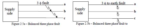
As shown above, this is routinely a balanced condition, and the utility owner will only be concerned about the positive sequence system to analyse faults. Each phase carries equal amount of currents which are displaced by 120°.
Typically, only 5% of the initial faults in a power system, are three phase faults with or without earth. Of the unbalanced faults, 80 % are line-earth and 15% are double line faults with or without earth and which can often deteriorate to 3 phase fault. Broken conductor faults account for the rest. Electrical Power Systems: Analysis, Security And Deregulation
By P. Venkatesh, B. V. Manikandan, S. Charles Raja, A. Srinivasan (2012) P.129
Symmetrical Component Analysis
According to EE 423 – Power System Analysis: Faults – J R Lucas – October 2005 p. 11, Unbalanced three phase systems can be split into three balanced components, namely
Positive Sequence (balanced and having the same phase sequence as the unbalanced supply), Negative Sequence (balanced and having the opposite phase sequence to the unbalanced supply) and Zero Sequence (balanced but having the same phase and hence no phase sequence). These are known as the Symmetrical Components or the Sequence Components and are shown in figure 2.10.
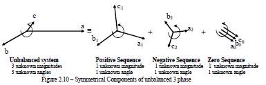
The unknown unbalanced system has three unknown magnitudes and three unknown angles with respect to the reference direction. Similarly, the combination of the 3 sequence components will also have three unknown magnitudes and three unknown angles with respect to the reference direction.
Asymmetric al Three Phase Fault Analysis
The most frequent form of asymmetrical (unbalanced) fault in a network is a single line to ground fault. A high percentage of faults in a system are line to ground faults. The other forms of asymmetrical faults are line to line faults and double line to ground faults.
The greater number of asymmetrical faults occur on transmission lines and in relation to this thesis in substations where they are susceptible to outside factors. Typical situations may include, lightening strokes to cause insulators to flashover, strong winds can cause switchgear failure, ice loading can cause mechanical failure of busbar or insulator and tree branches can cause short circuit.
Substation reliability analysis is fundamental for designing and planning the right circuit breaker rating and relay settings for the circuit.
Analysis of Asymmetrical Faults
As stated previously, the most frequent types of asymmetrical faults are single line to ground faults and line to line faults, with and without fault impedance. I will analyse these in further detail below.
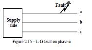
Single Line to Ground faults
Single line to ground fault can arise in any of the three phases. The method to evaluate single line to ground faults is to analyse one phase and the simplest process would be to analyse the phase ‘a’ as shown in figure 2.15.
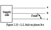
Line to Line faults
Line-to-Line faults can occur in a substation, with or without the earth, and with or
without fault impedance as shown in figure 2.20.
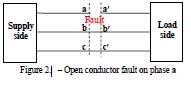
Broken conductor faults
When one or two phases of a balanced three phase system opens it establishes unbalance in the network and causes the flow of unbalanced currents. This materialises when one or two conductors of a line are broken due to a storm or if circuit breakers operate only on one or two phases leaving others still in service as shown in figure 2.21.
Simultaneous faults
Occasionally, there is a chance that more than one type of fault occurs simultaneously. This may all be short circuit faults, such as a single-line-to-ground fault on one phase, and a line-to-line fault between the other two phases. They may also be short circuit faults coupled with open conductor faults.
2.2.4 Short-circuit studies
Short-circuit analysis is required to determine:
- that circuit breakers are capable of clearing the short-circuit currents.
- that equipment, transformers, cables, lines etc are capable of carrying the short-circuit current for the appropriate time.
- protection settings, relay and fuse co-ordination.
For unbalanced faults, phase-to-ground, phase-to-phase, the model must contain three values for circuit and infeed impedance, namely, the positive sequence, the negative sequence, and the zero sequence.
The three (symmetrical components) of impedance are:
I. The positive sequence component which consists of three vectors equal in magnitude, displaced from each other by 120 degrees and having the same phase sequence as the balanced system i.e. Red, Yellow, Blue clockwise, rotating in an anti-clockwise sense.
II. The negative sequence component which consists of three vectors equal in magnitude, displaced from each other by 120 degrees and having opposite phase sequence as the balanced system i.e. Red, Blue, Yellow.
III. The zero sequence component which consists of three vectors equal in magnitude, in phase with each other and rotating in an anti-clockwise sense.
2.2.5 Substation Protection Failures
The protection system is implemented to protect the substation from experiencing a prevalent fault. Nevertheless, the protection system itself can also fail. For example, if current transformers, voltage transformers or High accuracy metering units fail, it is likely that wrong measurements are initiated to the protection system and the protection system may fail to detect the fault.
To avoid prevalent outages induced by faults in the substation protection system, switchgear components shall be protected by two separate protection systems. The substation consists of a main protection system and a back-up protection system if the main protection system fails.
2.2.6 Circuit Breaker Failures
The purpose of circuit breakers is to provide a fast, selective and reliable fault clearing protection system. Under normal conditions, the circuit breaker is required to carry the current and energize or de-energize parts of the substation. However, if there is a short circuit somewhere on the system, then the circuit breaker is the only high-voltage switchgear to protect the components in the substation. If the short-circuit cannot be removed promptly, the reserve protection will trip further sections of the substation, causing failures and outages.
The performance and reliability of circuit breakers is fundamentally significant. These conditions are not only implemented on new circuit breakers but also on old circuit breakers. Utility owners will also implement an operation and maintenance strategy to manage the life-cycle of their circuit breakers. In terms of reliability, the failure of a circuit breaker that causes discontinuation of one or more of its functions can be defined into major failures and minor failures/defects.
Some typical examples of major faults (mechanical and electrical) can be that the circuit breaker does not close or open on command, closes or opens without command, does not make or break the current, fails to carry the current, or locked in open or closed position.
Some typical examples of minor faults can be air/hydraulic oil leakage in the operating mechanism, small SF6 gas leakage due to corrosion or other causes, and change in functional characteristics.
2.3 Conclusion
During this chapter I have discussed in detail the reliability concepts and subdivision of reliability analysis of power systems. I briefly detailed basic concepts regarding reliability evaluation, such as reliability, failure probability, failure frequency and mean time to repair. I also carried out research on substation fault data which defines the reliability of a substation. This lead to the last part of the chapter which involved the important requirement for utility planners to select the most efficient and right substation configuration which best suit the consumer and the utility owner.
Chapter 3 – Substation Structures and Reliability Analysis Methods
3.1 Substation Structures
Transmission and distribution owners are required to meet performance standards and criteria that ensure an acceptable level of service. Service quality means continuity of supply. Requirements for continuity of supply are traditionally referred to as power system reliability. The reliability criteria for TSO & DSOs must address substation interruptions and to be able to effectively respond to incoming faults.
The substation is fundamental because it steps up or steps down AC voltage using transformer(s), it will break power flows, provide support to power flows and essentially transfers reliable electricity to its customers. Each substation must be analysed individually in greater detail as each substation can have different parameters. For example, substations positioned near large polluted factories, near the sea or on high ground can cause environmental fault problems. Further examples could be that substations vary in different sizes, have different configurations and supply contrasting loads that all influence fault analysis studies.
TSO & DNO planners are able to increase reliability on their substations by utilising the most efficient substation configuration available in their means. Ideally, the circuit and equipment inside a substation should be configured so that following a fault or during maintenance the supply remains available. The level of security of supply could be achieved by duplicating all circuits, but only at very high cost. Therefore, necessary to compromise between total security and the capital invested and early in the planning stage of a design it will be necessary to decide what configuration is to be offered. Often, more than one option is produced after which the advantages and disadvantages of each are considered before one is actually chosen. Some measure of redundancy is often adopted into all substation configurations which improves the security of supply.
There are a number of main layouts of circuit breakers and disconnectors at the junctions of circuits and at voltage transformation points. For this reason, each basic layout has quite different requirements for operations and control.
In transmission HV and EHV networks, the layouts tend to be more complex, due to the need for additional security and flexibility, since upon such networks a much larger number of consumers and indeed electrical load are dependent.
The main types are listed and addressed briefly for comparison and interest:
- one and a half breaker
- double busbar
- mesh arrangement
3.1.1 One and a half breaker
The one and a half breaker arrangement is popular in main transmission networks.
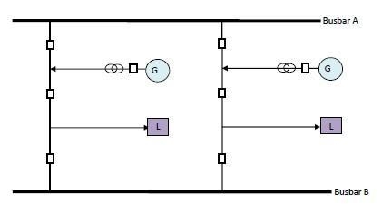
Figure 3.1.1 One and a half breaker arrangement
The one and a half arrangement is extremely flexible operationally and provides a high level of system security. If required any circuit breaker can be taken out of service for maintenance or repair without any circuit outage, unlike the double busbar arrangementwhere this is only true for the busbar breakers, couplers, and section breakers. It, however, utilises more circuit breakers than a fully equipped double busbar arrangement when there are in excess of eight circuits to connect. This is thus a design issue, flexibility and therefore security versus capital cost.
3.1.2 Double busbar
A double busbar arrangement.
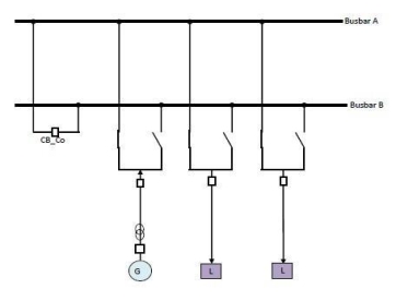
Figure 3.1.2 A double busbar arrangement
There are, however, some operational disadvantages to the 1½ breaker arrangement, such as the ability to achieve reasonably secure system splits when necessary for fault level control or load flow control. This together with the additional investment in costly circuit breakers often leads designers towards the double busbar arrangement.
3.1.3 Mesh arrangements
The mesh arrangement is a less common layout in highly interconnected main transmission substations and is generally applied at the junction of no more than four feeders (overhead lines or cables).
An auto-switching arrangement is employed for faults on individual circuits. For example, a line fault is cleared by its two corner breakers which also takes out of service its associated transformer. The appropriate corner isolators are opened automatically, and the breakers reclosed so restoring the transformer to service
The decision-making process for substation layout and hence the number of circuit breakers to be employed is always a balance between capital expenditure and the on-going risks in terms of system security. The mesh arrangement is thus much more common in sub-transmission and distribution power networks because they are cheaper to construct.
Mesh substations incorporating more than four circuit breakers are most uncommon in main transmission networks due to their inherent inflexibility and effect on system security.
Single, two and three breaker meshes are also employed. However, for most distribution networks the most common arrangement (utilities and major consumers) at ‘primary substations’, is the single busbar configuration. ‘Primary substations’ meaning intakes from the supplying transmission utility. It is usually found in two, three or four sections.
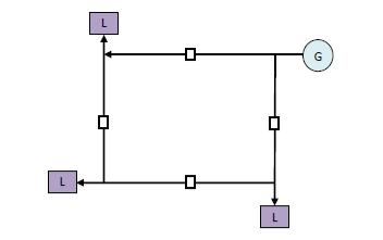
Figure 3.1.3 A mesh arrangement
3.1.4 Other arrangements include:
- Single busbar layout – A single busbar substation is a simple arrangement, and its reliability is far more limited than the other substation configurations. Typically, in the medium voltage class or high voltage class, this kind of arrangement is not considered out of reliability consideration.
- Double circuit breaker layout – At each circuit, there is only one bay, and two separate circuit breakers are used for the protection of this bay.
- 4/3 circuit breaker layout – This arrangement is very similar to the one-and-a-half circuit breakers configuration. The only variance is that, on one branch of the 4/3 circuit breakers substation, there are three bays connected with four circuit breakers. Therefore, one bay in this configuration shares 4/3 circuit breakers.
3.1.5 Defining a reliable substation structure
When selecting a substation arrangement, two main factors need to be considered, reliability and cost. Evidently, the substation arrangement that is more reliable will usually demand advanced level of protection and in-turn require an increase in budget. The substation layouts that differ from the typical double busbar arrangement are found to be more problematic to operate by system operators.
Among the said substation arrangements stated above, the single busbar configuration is the simplest and the most unreliable configuration. At medium voltage level and high voltage level networks, it is rarely applied.
The double circuit breakers arrangement is more reliable. Nonetheless, because there are two circuit breakers required for only one circuit, the costs of this configuration can be higher than the others. That is why this configuration is also not often applied.
The mesh substation also has a high reliability factor, but its complex construction will also increase the costs. Moreover, the complicated construction delivers a higher demand on the substation operators, which may cause more operational mistakes. Consequently, it is also not used frequently in reality.
The remaining three configurations (one-and-a-half circuit breakers substation, 4/3 circuit breakers substation and typical double busbar substation) are mostly used in the high voltage grid design.
Once the layout has been agreed, a reliable substation must be designed to meet future power supply requirements. It must also have adequate protection for the various types of faults and short circuits that can occur. This requires that circuit breakers, surge arresters, and other protective devices have the ability to interrupt the very high currents that can occur when a short circuit occurs. Relaying to detect such faults need to be provided and co-ordinated with the protective devices.
Power outages at transmission and distribution substations impacts heavily on the reliability of supply to the consumer. Utility owners are responsible for minimising outages, outage periods and impact on company assets. Power outages affects reliability and British Standard 7354 Design of High Voltage Open Terminal Substations, categorises substation service continuity as:
- Category 1 – No outage necessary within the substation for either maintenance or fault. Whilst a substation in this category does not required a system outage it does not necessarily provide security of supply for single faults even if the fault is limited to busbar and circuit breaker faults.
- Category 2 – Short outage necessary to transfer the load to an alternative circuit for maintenance or fault.
- Category 3 – Loss of a circuit or section.
- Category 4 – Loss of substation; for example, the single busbar scheme without bus sectionalisation for a fault in the busbar area.
3.1.6 Short circuit restraints
An efficient technique to reduce fault levels is to avoid designing parallel connections (transformers or power sources feeding the substation). Multi-busbar configurations with breaker devices tolerate the system to be separated or coupled through a fault limiting reactor. The system can also be split using breakers in a mesh or ring type substation arrangement. However, this involves conservative planning and operational strategies.
3.2 Substation Modelling with Different Types of Faults
3.3 Reliability Methods
Reliability analysis methods focused with interruptions are required to address three aspects: frequency, duration, and extent or severity. The extent or severity is the total number of end users or load affected, which is determined by the substation design. It is vital that in this thesis we consider all three factors because just focussing on two factors for example frequency and duration into a single appropriate measure may not be feasible. All three factors are important for different purposes. These factors are then used to measure indices and used in reliability analysis methods which different utility owners employ different methods and indices.
Utility owners and planners may employ different indices such as SAIFI, CAIFI, MAIFI, and MICIF to support them adopting the most efficient layout and equipment possible.
3.3.1 Determining a reliability strateg
A reliability planning process can be required to determine the most cost-effective way of reducing the risk associated with the substation and the assets while achieving the required level of service. The risk is measured in terms of the consequences of failure which can have financial, operational, safety, environmental, and regulatory effects.
Many utility companies may have asset reliability and maintenance policies which involve rolling, time-based cycles. This is not always efficient and may indeed be counter-productive as the disturbance caused during invasive maintenance may cause problems. In addition, most time-based servicing schedules do not identify or predict failure mechanisms and therefore do not provide information that could be used to make better-informed asset management decisions e.g. replacement versus refurbishment.
UK utilities generally use risk management analysis to determine the most effective type of maintenance with a three-stage process:
- identifying all hazards (HAZID) and operability issues (HAZOP);
- conducting a failure mode, effects and criticality analysis (FMECA); and
- selecting a maintenance policy
3.3.1.1 Identifying all hazards
This involves the identification of all potential hazards that present a risk to the asset performing its intended function. The system assets should be grouped into categories, for instance underground cable system or switchgear. Hazard identification (HAZID) and operability (HAZOP) should be carried out systematically for each individual asset in turn.
3.3.1.2 Conducting a failure mode, effects and criticality analysis (FMECA)
Here the consequences of the previously identified failure modes should be considered. The maintenance that can be performed to reduce or eliminate the chance of failure, and possibly mitigate or control the effects of failure, is reviewed and the possible levels of maintenance identified.
3.3.1.3 Selecting a reliability and maintenance policy
Based on the preceding analysis a suitable reliability and maintenance policy can be carefully chosen. Utility owner’s reliability and maintenance policies may comprise of a combination of routine and condition-based tests. The utility owner examined for this thesis uses reliability centred maintenance (RCM) as their reliability and maintenance strategy. However, due to the sensitive nature of their policies and information, I can only write about the generic processes of RCM and how it benefits substation reliability due to different faults.
3.3.2 Reliability Centred Maintenance (RCM)
Reliability Centred Maintenance (RCM) is an approach towards asset and has become a widespread and generally accepted practice. Over the last decade, UK utilities have started to introduce RCM schemes into their asset management strategies. RCM provides a formal and highly structured approach towards asset maintenance programmes. It provides a strategic framework for ensuring that any asset continues to perform as its user wants it to perform. In this thesis, I will present how RCM can be applied to substation reliability analysis and its assets.
3.3.2.1 Functions – What are the functions of an asset in its operating context?
Physical assets are bought and operated by companies to fulfil particular tasks. These assets are maintained in order that they will continue to do what their users want from them. It is important to note that the definition of what a user wants from an asset may be different to what the asset actually does.
RCM requires that an asset’s function be defined as what the user requires it to do rather than what the asset may be capable of doing. This change in emphasis to what an asset does from what it is provides a new way of defining the objectives of maintenance. Extending this idea, RCM implementation starts with defining the boundaries of the system (comprising individual assets) and succinctly describing the functional performance required of it. This is perhaps the most difficult RCM analysis task and is often not performed adequately.
3.3.2.2 Defining functions
Any asset must perform certain pre-determined tasks. However, simply describing these tasks is usually insufficient. Most tasks must be performed to a certain performance standard. A clear definition of function is essential to defining failures and how critical each failure might be. Failures are defined as the inability to perform described functions. It is possible to perform an RCM analysis on individual components however; the functional interdependence of the components is then lost.
A function definition is not complete unless it specifies as precisely as possible the level of performance required by the user (as opposed to the built-in capability).
3.3.2.3 Protective devices
Asset failure can prove very expensive both in terms of human safety and system downtime. Many measures are therefore put in place to reduce risk in the event of component or asset failure. They are categorised as below:
- alarms – to draw attention to abnormal events;
- system shutdown – in the event of failure;
- elimination or relief of abnormal conditions in the event of failure – for instance, safety valves or firefighting equipment;
- redundancy – to take over function in the case of failure; and
- prevention – to avoid failure in the first place, for instance, protective guards.
Having such protective devices very often directly affects the maintenance requirements of the function being protected. Very often they require more maintenance attention than the primary function. Each protective device needs to be looked upon and dealt with as a separate function.
3.3.2.4 Functional Failures
Once an asset’s functions and performance standards have been properly and fully detailed, then functional failure is simple to define. If an asset fails to perform its functions to the specified performance standards, then it can be said to have functionally failed.
It follows that, as an asset becomes increasingly complicated in terms of the number of functions it fulfils, the number of ways in which it can fail increases accordingly.
In defining functional failures, a sharp focus is often put on the original definitions of the functions and the performance standards. If in the light of failure definitions performance standards need altering, then this should be done.
3.3.2.5 Failure Modes / Causes of Failure
A failure mode is an event that causes a functional failure. It is the specific cause for an asset failing to continue to perform its functions.
In defining a failure mode, specific possible scenarios should be foreseen and described. A failure mode should be recorded and defined if it is considered reasonably likely to occur. It is important to give enough information about the failure cause for a remedial plan to be formed. There should not, however, be so much detail that too much time and effort is spent on the exercise. The information described at this phase in the process is important to the development of a failure management strategy.
3.3.2.6 Categories of failure modes
When studying and defining failure modes it is useful to separate them into three distinct categories:
- capability falls;
- desired performance increases; and
- the asset was not able to meet the required performance from the outset.
3.3.2.7 Capability falls
An asset fails in this way when its performance capability falls below the required performance standard. Many assets are expected to deteriorate with time and use. This is usually seen as a natural development in the life of the asset and is often predicted to happen at a given rate. This rate can of course be reduced or increased for many reasons. These should be identified and detailed.
3.3.2.8 Desired performance increases
Occasionally, assets are stressed beyond their design performance levels. This can happen for many reasons which are most easily identified when broken down into the subcategories listed below:
- sustained deliberate overloading;
- sustained unintentional overloading; and
- sudden unintentional overloading
3.3.2.9 Sustained deliberate overloading
This usually occurs simply for operational reasons. Sometimes assets are excessively stressed in an attempt to get more out of the system i.e. circuits are made to carry loads beyond their design capacity as demand outstrips forecasts. Of course this has a direct effect on the long-term reliability of the system and may well be economically disadvantageous.
3.3.2.10 Sustained unintentional overloading
An asset can be forced into operating beyond its capabilities due to failure elsewhere in the system. Very often failures go unnoticed until a different component fails due to the excessive strain it has been under as a result.
Much of the UK distribution and transmission system has redundant capacity to allow for failures, particularly at the higher voltages. However, where this is not the case, or when multiple failures happen, circuits and their components can become overloaded.
3.3.2.11 Sudden unintentional overloading
Many systems fail due to sudden and often unintentional increases in applied stress. Components in electrical power systems are particularly prone to this type of failure where assets can be exposed to voltage and current surges, often due to faults elsewhere on the system.
Lightning can put extremely high electrical surges onto distribution systems. Although protection devices such as surge arrestors and arcing horns exist to reduce its effect, it can on occasion lead to catastrophic failure.
3.3.2.12 Initial capability too low
Occasionally instances arise where an asset is not capable of meeting the desired performance standard of a function when the asset is first installed. This usually only applies to secondary functions or where a performance standard is ambiguous or difficult to quantify.
3.3.2.13 How does it affect production or operations?
Each failure mode should be looked at in the context of its direct effect on the operation of the system within which it works. Some failures may completely stop an operational process while others may reduce performance or have no immediate effect on performance at all.
In some instances, a failure can only be repaired during downtime. Where this is the case, the length of this downtime should be calculated and recorded. If spare components are required to fix the problem, then downtime should be calculated according to the currently used spare stock policy.
Areas that should be considered when assessing the effect of a failure mode are:
1. how product quality or customer service are affected by the failure
2. if there is a penalty associated with a reduction in product or service quality
3. whether the operation of other systems are affected
4. whether a failure leads to increases in overall operating costs in addition to the cost of repair
3.3.2.14 What physical damage is caused by the failure?
Assessment of physical damage caused by a failure is necessary in determining the effect of the failure on operations and assessing downtime etc.
3.3.2.15 What must be done to repair the failure?
Similarly, the steps required to get the system back to a satisfactory condition must be set out in order to assess the effect of a failure mode on operations.
Most modern systems have more complicated patterns of failure. The graphs in the figure below show six distinct patterns of probability of failure against operating age commonly found in electrical and mechanical systems.
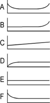
Pattern A This is the well-known ‘bath-tub’ curve. There is an initial high incidence of failure, called Infant Mortality, followed by a constant, or gradually increasing, period and finally a wear-out period.
Pattern B Here there is a constant, or gradually increasing, probability of failure leading to a final wear-out zone.
Pattern C Pattern C again has a constant, or gradually increasing, probability of failure but with no distinct wear-out zone.
Pattern D Here there is low probability of failure when the asset is new but a constant or steadily increasing probability thereafter.
Pattern E Pattern E shows a constant probability of failure at all ages.
Pattern F A high infant mortality levels out to a constant or very slowly increasing probability of failure.
3.3.2.16 RCM stage by stage technique
RCM is a process used to determine the maintenance requirements of any physical asset in its operating context.
The RCM process involves asking seven questions about the asset or system under review, as follows:
1. What are the functions and associated performance standards of an asset in its operating context?
2. In what ways can it fail to fulfil its functions?
3. What are the root causes of the failures?
4. What are the effects of the failures?
5. What are the failure consequences – does it matter?
6. What can be done to avoid the consequences?
7. What action is required if nothing can be done to avoid the consequences?
Having comprehensively answered the seven questions, a clearly defined task selection process is undergone to determine whether an asset is likely to fail and if so what action should be taken to avoid it.
3.4 Conclusion
In this chapter, the typical substation configuration layouts were introduced. The modelling of the three main types of substation layouts were created with different faults impacting them and the result of these faults.
This chapter also discussed the importance of reliability analysis methods for utility owners to constantly help keep the substation fault free and reliable as much as possible.
Cite This Work
To export a reference to this article please select a referencing stye below:
Related Services
View all


Related Content
All TagsContent relating to: "Energy"
Energy regards the power derived from a fuel source such as electricity or gas that can do work such as provide light or heat. Energy sources can be non-renewable such as fossil fuels or nuclear, or renewable such as solar, wind, hydro or geothermal. Renewable energies are also known as green energy with reference to the environmental benefits they provide.
Related Articles

DMCA / Removal Request
If you are the original writer of this dissertation and no longer wish to have your work published on the UKDiss.com website then please: