Strategy to Reduce Glasgow Clyde College’s Carbon Footprint
Info: 17232 words (69 pages) Dissertation
Published: 6th Jan 2022
Tagged: EnergyClimate Change
Table of Contents
- Project brief
- Project summary
- Glasgow Clyde college overview
- Stakeholders
- Stakeholder communication
- Project objectives
- Gantt chart
- Verification strategy
- Project risks
- Business case
- Scottish renewable energy targets
- Feed in tariffs
- Renewable heat incentive
- Renewable technology overview
- Location information for Anniesland College
Project brief
This project has been commissioned with an aim to reduce Glasgow Clyde College’s carbon footprint, whilst providing an educational engineering case study on renewable energy for engineering systems. This case study combined with selected installation itself will be used to educate both students and the general public on this subject matter.
The framework of the project is to research potential micro generation renewable energy sources and existing technologies that could be used to partly sustain and reduce the energy needs of the Glasgow Clyde College Anniesland campus engineering department.
Of the researched renewable technologies, a report is to be prepared with a conclusion of the system or systems that are best suited for recommendation within the requirements of the specification and project framework.
A business case will be created for each system or systems to be used within the facility, which will address the following:
- Potential energy generation capability.
- Location suitability.
- System suitability.
- System operation costs.
- Maintenance requirements and costs.
- Potential educational benefit.
Project summary

Researched renewable/microgeneration technologies that could potentially be integrated into Glasgow Clyde colleges Anniesland land campus. Chosen system(s) must generate enough energy to partly sustain and reduce the energy needs of the Glasgow Clyde college Anniesland campuses, engineering department workshops.
Key parameters of the project:
- The project must be delivered in its entirety within the constraints of the budget.
- Allocated funds budgeted for the project is £500,000.
- The chosen system(s) should generate sufficient cost savings to recoup the initial investment within a 20-year period.
- Project must be delivered within the set timescale of 34 weeks.
- Evidence for system(s) justification must be validated via verification strategy. System Justification should include analysis of results test and investigation data.

Glasgow Clyde college overview
Glasgow Clyde College is one of the largest further education institutions in Scotland.
Situated in the thriving city of Glasgow, the multi-campus college offers a wide array of educational and career opportunities across its three locations. Sites are conveniently located across the expanse of the city, composed of three key campuses – Anniesland, Cardonald and Langside – following the merger of each individual college in August, 2013.
Glasgow Clyde College caters to over 7,000 full-time students and 20,000 part-time students. The college benefits from years of industry experience and exceptional teaching standards, all delivered in modern facilities and champions the development of both the local and national economy.
A total redevelopment of Anniesland campus at Hatfield Drive was completed and opened in 2010
The Anniesland Campus is located in the west end, three miles from Glasgow city centre. The Campus is situated behind Great Western Road (A82) and is close to the Clyde Tunnel.
Address:
Anniesland campus
Glasgow Clyde College,
19 Hatfield Dr,
Glasgow
G12 0YE
Stakeholders
Key stakeholders:
- Glasgow Clyde college principal (Susan Walsh).
- Glasgow Clyde college vice principals
- Glasgow Clyde College board.
- Scottish funding Council.
- Facilities Manager.
- Department heads.
- College lecturers.
- College students.
- Project manager (David R Shields).
- Energy supplier.
- Local planning authority.
- Solar panel manufacturer.
- Wind turbine manufacturer.
- Geothermal heat pump manufacturer.
- Electrical contractor.
- Ground works contractor.
- Building contractor.
- Local residents of Glasgow Clyde College.
- Local businesses.
- Local politicians.
- Media.
Stakeholder project interests
Glasgow Clyde College principal
Project interests:
- Acts as champion of the project.
- Accountable delivery of plan benefits associated with the project.
- Insurer’s resolution of issues escalated by the project manager or the board.
- Will make key organisational/commercial decisions for the project.
- Assure the availability of essential project resources.
- Approves the budget and decides tolerances.
- Lead project steering board
- Execute managerial control over elements of the project and its outputs.
- Policy and process owner who determines organisational administrative policy and procedures.
- Manages staff who will operate/maintain the system at local level and staff who indirectly input and directly extract data.
- Involvement in project board.
- Will have regular meetings with project leader.
- Will ultimately sign off on funding for the project.
- Will be involved in regular meetings with local residents and businesses and other stakeholders.
Glasgow Clyde college vice principals
Project interests:
- Insurer’s resolution of issues escalated by the project manager or the board.
- Will make key organisational/commercial decisions for the project
- Assure the availability of essential project resources.
- Approve the budget and decides tolerances.
- Lead project steering board
- Execute managerial control over elements of the project and its outputs.
- Policy and process owner who determines organisational administrative policy and procedures.
- Manages staff who will operate/maintain the system at local level and staff who indirectly input and directly extract data.
- Involvement in project board.
- Will have regular meetings with project leader.
- Will sign off on funding for the project.
- Will be involved in regular meetings with local residents and businesses and other stakeholders.
Glasgow Clyde College board
Project interests:
- Champions the project and raises awareness at senior level.
- Approves strategies, implementation plans, project scope and milestones of the project.
- Overseeing progress of the project and resolving strategic and policy issues.
- Communication with other key organisational representatives and stakeholders.
The Scottish funding Council
Project interests:
- Raise and allocate funding.
- Greater innovation of the local economy.
- Delivery of high-quality learning and teaching.
Facilities Manager
Project interests:
- Maintenance and repair of Glasgow Clyde Collage facilities.
- Manage staff who will operate the new system at local level and staff who indirectly input and directly extract data.
- Scheduling of works to be carried out around lectures.
- Will be involved in briefing/meetings in regards to the project.
Department heads
Project interests:
- Manage staff who will operate the new system at local level and staff who indirectly input and directly extract data.
- Scheduling of lectures around works to be carried out.
- Will be involved in briefing/meetings in regards to the project.
College lecturers
Project interests:
- Allocation of classrooms of the lectures around plan works.
- Disruption to lectures.
- Use of project outputs of the project for learning and development of engineering systems.
- Involvement in user group and briefing/meetings in regard to the project.
College students
Project interests:
- Disruption to lectures.
- Learning and development benefits of project outputs.
- Continuity/safety of end output.
Project manager (David Shields)
Project interests:
- Recruitment of project team and consultants.
- Coordination of partners and working groups engaged in project work.
- Implementation of project planning control.
- Developing and maintaining project plan.
- Design specifications.
- Budget adherence of the project.
- Time management of the project.
- Quality of delivery.
- Project communication.
- Will be involved in regular meetings with local residents and businesses and other stakeholders.
- Maintain of corporation and communication of project team.
Energy supplier
Project interests:
- Security and Manner of connection to the National Grid.
- Quality of generated power being fed into the grid.
- Amount of power being generated.
- Accuracy of calibration for the feed in tariff.
- Insurance and liability.
Local planning authority/Council
Project interests:
- Project design and plan.
- Visual impact of project on local residents and area.
- Noise pollution impacts of the project on local residents and area.
- Environmental impacts.
- The effect on a protected area such as an Area of Outstanding Natural Beauty or other designated areas.
- The colour and appearance of the modules, particularly if not a standard design.
- Local resident’s considerations and objections.
Solar PV panel manufacturer
Project interests:
- Solar PV panel design and operation requirements.
- Location and orientation of panels.
- Installation and maintenance plans.
- Timeframe of the delivery of project.
- The logistics and access.
- Media and public opinion of the project.
Wind turbine manufacturer
Project interests:
- Turbine design and operation requirements.
- Location and orientation of turbines.
- Installation and maintenance plans.
- Timeframe of the delivery of project.
- Logistics and access.
- Media and public opinion of the project.
Ground/Air source heat pump manufacturer
Project interests:
- Geothermal heat pump design and operation requirements.
- Air source heat pump design and operation requirements.
- Location and orientation of heat pump installation.
- Installation and maintenance plans.
- Timeframe of the delivery of project.
- Logistics and access.
- Media and public opinion of the project.
Electrical contractor
Project interests:
- Installation design plan.
- Timeframe and allocation.
- Logistics and access.
- Health and safety/risk assessment.
- Logistics and access to site.
- Schedule of work.
- Current schematic of the site.
Ground work contractor
Project interests:
- Installation design plan.
- Timeframe and allocation.
- Logistics and access.
- Health and safety/risk assessment.
- Logistics and access to site.
- Schedule of work.
- Current schematic of the site.
- Planning permission
Building contractor
Project interests:
- Installation design plan.
- Timeframe and allocation.
- Logistics and access.
- Health and safety/risk assessment.
- Logistics and access to site.
- Schedule of work.
- Current schematic of the site.
- Planning permission.
Local residents of Glasgow Clyde College
Project interests:
- Visual aspect impact.
- Infringing noise pollution.
- Disruption of plan works.
- Increased site traffic.
- Impact on character of the area.
Local businesses
Project interests:
- Visual aspect impact.
- Infringing noise pollution.
- Disruption of plan works.
- Increased site traffic.
- Impact on character of the area.
- Potential impact on business.
Local politician
Project interests:
- Public and media opinion of the project.
- Sustainability of the project.
- Legacy of the project.
- CO2 emissions targets (2020 Kyoto agreement).
- Visual aspect impact.
- Infringing noise pollution.
- Disruption of plan works on the local area.
- Increased site traffic.
- Impact on character of the area.
- Potential impact on businesses and local residents.
Media
Project interests:
- Project delivery time and budget
- Funding sources.
- Public opinion.
- Impact on local businesses and residents.
Stakeholder communication
Team Charter
Project objectives
Short-term objectives
- Build project team.
- Layout project plan.
- Identify suitable renewable microgeneration technology’s.
- Successful analysis of test results and projections.
- Create verification strategy.
- Construct business case for the commissioning of the project.
- Build and develop relations with stakeholders.
- Successful integration of proposed systems within the college facility.
- Successful delivery of project within set timeframe.
- Successful delivery of project to budget.
Long-term objectives
- Return of initial investment through generative savings within allocated 20-year timeframe.
- Reduction in the carbon footprint produced by the college facility.
- Reinvestment of funds raised by generated energy surplus.
- Educational inclusion of a system(s) within the curriculum.
- Generation of future business contracts.
- Legacy of Glasgow Clyde college within the engineering renewable technology field.
- Raised awareness of carbon reduction and renewable technologies.
Verification strategy
Determining the suitability of the proposed renewable technologies to be integrated within the Anniesland campus facility, requires the consideration of multiple factors. A vetting process must be implemented and applied to each proposed system(s).
Verification process:
- Research existing renewable technologies stated operational generation capabilities.
- Confirm stated capabilities via test analysis and calculation.
- Assess suitability for location.
- Assess system suitability and costings.
- Evaluate system operational costs.
- Evaluate system maintenance requirements with known operation lifespans.
- Evaluate test criteria and review the quality of assessor findings at each stage.
- Rate each system(s) with numeral value on the specified criteria:
- Generating capabilities
- Location suitability
- System operational costs
- Maintenance requirements and costs.
- Document findings and Record evidence.
Strict adherence to verification strategy is vital to ensure the successful delivery of the project, within the specified timeframe and on budget.
Project risks
| Risk | Likelihood | Impact | Risk reduction Measures |
|
Failure to deliver project within set budget. |
Low |
High |
|
|
Failure to deliver project within specified timeframe. |
Medium |
High |
|
|
Stakeholder objections to the project |
Low |
Medium |
|
| Risk | Likelihood | Impactk | Risk reduction Measures |
|
Failure to acquire required funding |
Medium |
High |
|
|
Failure to generate the investment return within the set 20-year timeframe. |
Medium |
Low |
|
|
Failure to attain planning permission |
low |
high |
|
Business case
Objective
The objective of this project is to incorporate renewable technologies within the Anniesland campus facility, with the aim to generate sufficient energy to meet the total power/ requirements of the engineering department and the associated workshops. All surplus energy not consumed by the engineering Department will be fed back into the grid generating funds via feed in tariffs subsidising the energy requirements of the rest of the Facility.
Current situation
With growing energy requirements combined with ever increasing energy costs and shrinking college budgets, Glasgow Clyde college has to be proactive in tackling the issue. In the UK in 2015, renewable energy provisionally accounted for 8.3 per cent of final energy consumption. Between 2014 and 2015 electricity generation from renewable sources increased by 29 per cent.
It is of great importance that all organisations, businesses and homeowners commit to reducing the carbon footprints created by their associated buildings inefficiency’s.
Benefits
The primary advantage of this project is financial. The proposed microgeneration systems if implemented successfully, will generate enough energy to enable the engineering Department to be self-sustaining, which in turn would dramatically reduce the facilities overall energy consumption. The savings generated from the proposed systems would recoup the initial investment within 20 years. After the initial investment has been recouped all profits can be reinvested within college facility.
Renewables are the fastest growing engineering market and is predicted to be the one of largest markets within the next 50 years, replacing carbon-based energy sources currently being used. As more and more engineering companies focus on the development of renewable technology, they require their workforce to be trained up and familiarised with said technologies. When Glasgow Clyde College put its engineering courses out for tender, it will have the ability to use the integrated system of this project within the prospectus that the college offers to entice companies to sign up to the colleges curriculum.
The successfully integrated systems of this project will be used as a teaching aid by lectures when demonstrating renewable technologies, engineering systems and electrical power generation. With the ability to physically show students, fully working and successfully integrated system in use. Students will have better comprehension and understanding of systems in use in industry.
Climate change is the driving force behind renewable technologies, with the aim to reduce the amount of the greenhouses gas’s such as carbon dioxide being emitted. Greenhouse gases have an important role in helping the earth trap and retain heat for life to exist. An increase in the amount of carbon dioxide into the atmosphere could lead to overall warming of the climate. Reducing the carbon footprint within the college will in turn contribute to reducing the amount of carbon dioxide that is emitted into the atmosphere. The successful installation of the project will contribute to the achievement of the Scottish and UK government’s target by the 2020. The 2020 climate & energy package (Kyoto agreement) is a set of binding legislations to ensure the EU meets its climate and energy targets for the year 2020.
The package sets three key targets:
- 20% cut in greenhouse gas emissions (from 1990 levels).
- 20% of EU energy from renewables.
- 20% improvement in energy efficiency.
Recommendation
Success criteria
The success of the project can be measured by the securing of the key short and long-term objectives:
- Successful integration of proposed systems within the college facility.
- Successful delivery of project within set timeframe.
- Successful delivery of project to budget.
- Return of initial investment through generative savings within allocated 20-year timeframe.
- Reduction in the carbon footprint produced by the college facility.
- Reinvestment of funds raised by generated energy surplus.
- Educational inclusion of a system(s) within the engineering curriculum.
- Generation of future business contracts.
- Legacy of Glasgow Clyde college within the engineering renewable technology field.
- Raised awareness of carbon reduction and renewable technologies.
Support required
The successful delivery of the project is dependent on multiple factors:
- Granting of required £500,000 budget.
- Approval of planning permission by Local planning authority/Council.
- Stakeholder cooperation.
- Accreditation by the Microgeneration Certification Scheme (MCS)
- qualification for the feed in tariff scheme.
- Cooperation of college staff and student body.
Next step
Recommendation/Solution
this section should include a couple of different options but ultimately you must commit to your recommendation.
- Success criteria/measures
- what will change as a result of your intervention? How will you know?
- Support required
- indicate what support you need from outside resources to achieve your goals.
- Next step/pain when
- once you have approval what are some of your key milestones that will come next? When we commit to finish/deliver?
Scottish renewable energy targets
Scottish Energy Strategy, which sets out the Scottish Government’s vision for the future energy system in Scotland, to 2050. It articulates the priorities for an integrated system-wide approach that considers both the use and the supply of energy for heat, power and transport.
The Scottish government’s target for renewable electricity generation, is for renewables to generate the equivalent of 100% of gross annual consumption by 2020, with an interim target of 50% by 2015. Using 2013’s gross consumption as a proxy for 2014, around 49.8% of Scotland’s electricity consumption came from renewables in 2014, up from 44.4% in 2013. This (provisionally) means that the 50% renewable electricity target for 2015 has almost been met one year ahead of schedule.
Key renewable targets
- 100% electricity demand equivalent from renewables by 2020.
- interim target of 50% electricity demand equivalent from renewables by 2015.
- 12% heat demand from renewables by 2020.
- At least 30% overall energy demand from renewables by 2020.
- 500 MW community in locally owned renewable energy by 2020.
Feed in tariffs
To encourage the general public and businesses to invest in small-scale renewable and low carbon electricity generation technologies the UK government, developed the feed in tariff scheme.
The scheme gives members general public, businesses or organisations who have installed eligible solar PV wind, hydro, or micro CHP systems the ability to be paid for any surplus energy the feedback into the National Grid.
All policy and legislation regards to the feed in tariff scheme are made by the Department of business, energy and industrial strategy (BEIS).
The feed in tariff scheme is regulated by Ofgem, who also administers the scheme under Ofgem E-Serve.
Eligible renewable and low carbon electricity generation technologies benefit from the feed in tariff scheme through three avenues:
- Generation tariff: Registered systems will be paid for every kilowatt said system generates. The feed in tariff levels are guaranteed for 20 years and are index linked.
- Export tariff: All surplus energy not consumed is fed back into the grid. A rate is paid for each unit exported back into the electrical grid.
- Savings on energy bills: As the facility will be generating its own output of the less will be required to be bought from the energy supplier.
In order to qualify for entry into the feed in tariff scheme both installers and the renewable technology systems used must be certified under the Microgeneration Certification Scheme (MCS), with the exception of either hydro or anabolic suggestion systems which require to go through the ROO-FIT process. The feed in tariff supplied is dependent on the eligibility date and the properties Energy Performance Certificate (EPC) rating for solar PV systems.
Feed in tariff compatible technologies types
- Solar photovoltaic (PV)
- Wind turbines
- Hydroelectricity
- Anabolic digesters
- Micro combined heat and power (CHP)
| Technology | Capacity | Higher rate tariff |
| Solar PV | <10 kW | 4.11p /kWh |
| Solar PV | 10- 50 kW | 4.32p /kWh |
| Wind | <50 kW | 8.26p /kWh |
| Hydro | <100 kW | 7.63p /kWh |
| Micro-CHP | <2 kW | 13.45p /kWh |
Energy suppliers that have been granted feed in tariff licences by Ofgem, are tasked with administrating of the both the applications for the scheme and the feed in tariff payments.
All large energy suppliers are required by law to be feed in tariff licences.
Smaller energy companies are not required by law attain a feed in tariff licence however the majority of the smaller suppliers have opted in to the scheme.
Feed in tariff licensees
Voluntary Licensees:
- Affect Energy
- Arto.Energy
- Bristol Energy
- Ecotricity.
- Eneco Energy Trade BV
- Engie Power Ltd
- F & S Energy Ltd
- Flow Energy Ltd
- Foxglove Energy Supply Ltd
- Good Energy
- Haven Power
- Home Counties Energy plc
- Igloo Energy
- iSupply Energy
- Limejump Energy
- LoCO2 Energy Supply Ltd
- Mongoose Energy
- Neas Energy Ltd
- Opus Energy
- Our Power Supply Ltd
- PX Holdings
- Robin Hood Energy
- Sinq Power Ltd
- Spark Energy
- Symbio Energy LLP
- Texas Retail Energy, LLC
- Total Gas & Power
- Tradelink
Mandatory Licensees:
- British Gas
- E.on
- EDF energy
- First Utility
- npower
- Ovo Energy
- ScottishPower
- SSE
- The Midcounties co-operative Ltd
- Utilita
- Utility Warehouse
Renewable heat incentive(RHI)
In 2014, in an effort to encourage the general public and private sector businesses to invest in renewable heat technologies that will contributing to the 2020 renewable heating target of 12%, the UK government introduced the renewable heat incentive (RHI).
All policy and legislation regards to the renewable heat incentive are made by the Department of business, energy and industrial strategy (BEIS).
The renewable heat incentive is regulated by Ofgem, who also administers the incentive under Ofgem E-Serve.
The renewable heat incentive gives members general public, businesses and organisations who have installed eligible renewable heating technologies, the ability to be paid for the renewable heat energy produced by an installed system.
RHI payments will be paid quarterly over the seven-year period of the scheme membership. Payment of the RHI tariff is index linked to either the retail price index (RPI) or the consumer price index (CPI), depending on when in the tax year the application to the RHI membership scheme is submitted. Applications submitted before 1st April will be adjusted in line with the Retail Price Index (RPI) and subsequently adjusted by the consumer price index (CPI) for applications submitted on or after the 1st April.
The amount of RHI payments they can be expected is dependent on a number of factors including the type of renewable heat technology installed, the date of which the installation is commissioned. Generally, RHI payments will be calculated by estimation however some installations may be calculated by metering.
Current RHI tariffs
RHI Eligible renewable heat technologies
- Biomass boilers
- Wood fuelled
- Back boiler combined
- Supplied by BSL registered supplier
- Biomass pellet stove with integrated space heating capacity
- Back boiler combined
- Supplied by BSL registered supplier
- Ground to water heat pumps
- Air to water heat pumps
- Solar thermal panels
- Providing hot water
- Flat plate systems
- Excavated tube systems
RHI compliance and obligations
- All members of the RHI scheme must submit an annual decoration stating that all responsibilities have been met.
- All RHI scheme members with installed biomass systems, must source biomass fuel from the biomass suppliers list (BSL), evidence in the form of receipts may be requested in annual decoration.
- The Installed system must stay within the eligibility criteria in which the system was originally commissioned.
- All accredited heating systems must be kept in good working order.
- RHI members must comply with all conditions relating to accreditation (supplying of requested meter readings etc.).
- RHI members must notify Ofgem of any overpayments and repay any excess.
- RHI members have to comply with all administrative requirements set by Ofgem.
- RHI members informed of a site visit, must cooperate within reason with either the Ofgem or Department of business, energy and industrial strategy representatives and allow access to the site to collect data.
- RHI members must comply with all requirements necessary for the scheme review and evaluation.
Renewable technology’s

Photovoltaics (PV)
Design and operation
photovoltaic systems, more commonly known as solar panels systems convert light radiation produced by the sun into DC electricity.
A solar panel is made from layers from our semi-conducting material, typically silicon and works by allowing photons in the sun’s radiation, to knock electrons free from atoms, creating an electric field across the layers.
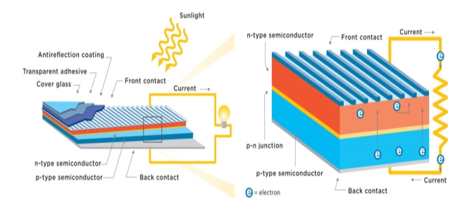
Solar panels are comprised of many photovoltaic modules which in turn are made up of many photovoltaic cells that have been linked together. The Solar panels are linked together to form solar arrays, now common place on rooftops across the UK.
As the electrical energy produced by a solar array is direct current (DC), a DC / AC inverter is required to convert the direct current into the alternating current before it is fed through the generation meter and into the consumer unit for distributed into the building the mains supply. If energy is not required at the point of generation it is fed through the electricity meter and exported out into the National Grid. All electrical energy exported is bought by the energy supplier via way of an export tariff in conjunction with the government backed feed in tariff scheme.

Solar Inverters
Solar inverters aka grid-tied inverters convert the direct current (DC) electricity produced by PV arrays into alternating current (AC) that can be used to run appliances in both residential or commercial applications and more importantly can be exported back into the National Grid.
There are two types of solar inverter currently available, a string or central inverter and micro inverter.
String or central type inverters are connected to multiple solar panels or large arrays that have been linked together.
For optimum efficiency within this type of system, all of the individual solar panel units are required to be operating under the same conditions as string inverter system can only perform as well as its lowest-performing panel. If shade dirt or debris affects one of the panel’s performance, the whole system operates at the same diminished capacity. If a branch of a tree with the cast shade onto one of the solar panels within the system it would have a detrimental impact on energy production.
For larger arrays that are affected by different levels of shading or it is not possible for all of the individual solar panel units to be oriented in the same direction, additional string inverter may be required.
Micro-inverters are connected into each individual solar panel in the array. In this type of system, the collective solar panel units do not all required to operate under the same conditions for optimal efficiency. If shading was cast onto a portion of the array, only the individual panels would be affected, while the remaining panels in the array will still operate at their optimum capacity. The improvement in generating efficiency in micro-inverter over string type inverters is estimated to be between 5% and 20%, ultimately this increases the system’s ability to successfully harvest solar energy and increase the potential income generated from the system.
String inverter |
Micro-inverter |

| String inverter | Micro-inverter | ||||
| Positives | Negatives | Positives | Negatives | ||
| Performance
|
Performance
|
Performance
greater energy harvest. |
Performance
|
||
| Reliability
|
Reliability
|
Reliability
|
Reliability
|
||
| String inverter | Micro-inverter | ||||
| Positives | Negatives | Positives | Negatives | ||
| Installation
|
Installation
|
Installation
|
Installation
|
||


There is a vast spectrum of inverters available ranging in size, specifications and manufacturers.
When selecting an inverter there are four key characteristics that must be taken into account:
- Maximum and minimum amounts of DC electricity the inverter is capable of converting (In watts).
- Maximum input voltage.
- Initial input voltage or start-up voltage.
- maximum power point (mpp) voltage range.
The size and generating capacity of the solar array at will dictate what an inverter specification will be required.
If the solar array generates a higher voltage than the maximum input voltage the inverter is capable of handling, the electronics could be irreversibly damaged, however in turn if the initial input voltage or start-up voltage is rated to high the system will not convert any other energy solar panel producers until the initial input voltages is achieved.
It is common practice within the UK have an inverter with a lower power rating than the array. Typically, a 3kWp array will be connected to inverter of between 2.4kW and 3.3kW. The setup ensures the initial input voltage and maximum power point voltage range are achieved as often as possible for optimal power generation and It is unlikely the array will generate its rated efficiency for prolonged periods of time.
Mounting systems


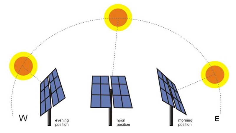
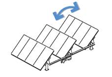
PV system(s) have the capability of providing enough AC electricity to power anything from single unit utility devices such as street lights and signs to residential properties, right up to large-scale energy production. To improve the PV systems generating performance a tracking systems can be employed to enable the panels to track the suns progress in the sky. Solar arrays with integrated tracking systems can produce up to 30% more cloudy the static arrays.
Increased associative installation costs or track system is beneficial when deployed with larger scale solar array systems however it is does not prove to be cost-effective in small-scale arrays.
Solar panels require to be a fixed to structures, or erected via frames for mounting system which can be categorised into three types.
1. Ground Mounted
- Typically, larger scale arrays where solar panel racks mounted on to steel A-frames that are secured to the ground via concrete pile, ground screws or rammed earth technique.
2. Roof Mounted
- Solar panel racks are mounted onto angled frames at an angle of 15° on flat roof structures to allow an optimal angle for solar generation and are normally weighed down with ballast to hold the panels position.
- Tracks like brackets are affixed onto pitched roofs that are suitably angled for solar generation, the solar panels racks are mounted onto the brackets which are secured in place with roof anchors and linked together to form a solar array.
- Roof integrated systems are typically employed on new buildings or on buildings that are being reroofed, the systems you use or tiles to replace existing tiles or slates to form an array or integrate panels into the roof itself with flashing kits to ensure the roof structure remains water tight.
3. Pole Mounted
- Typically used were ground mounting is not suitable. Multiple poles can be erected to form larger scale arrays.
- Pole mounted systems typically have greater efficiencies as a result of superior air cooling improving the panels performance.
All roof mounted installations must comply with the building regulations, roof and when loading must be taken into account when planning the installation of a PV system.
If the proposed PV system with increased loading of the roof structure in excess of 15% of the structures original load it is concluded it is considered to be a material change of the building structure and formal building regulation approval is required before work can commence.
Installers who are members of the part A, competent person scheme (CPS) are qualified to access roof structure loading and make a judgement as to the PV system’s weight increasing the loading by greater than 15% otherwise a local building control officer must be consulted before any work is to be carried out.
Maintenance

The maintenance requirements for solar PV panels are minimal, to ensure optimal generating performance the panels must be kept clean and free from debris. In most installations, the panels are tilted at raised angle above 15° to maximise the amount of light energy being captured, as a beneficial by-product of this rainfall actively cleans the panels.
It is of the utmost importance that surrounding trees and greenery are cut back and maintains, If the solar PV array becomes overshadowed as a result of vegetation growth the generating performance of the system will be greatly diminished.
Bimonthly maintenance checks are recommended to ensure the system is operating within system parameters.
Maintenance checks to include:
- Check panel is clean and free from debris.
- Check greenery and vegetation growth is not impacting on the system.
- Check Inverter for fault signals.
- Check and Compare energy generated against weather conditions.
Solar PV panels have an operating life expectancy of 25 years to however the solar inverter has an expected operating life of 15 years, at a cost of £800-£2000 this needs to be factored into any maintenance and running cost in projections.
Wind turbines

The UK is a wind rich country, 40% of all Europe’s wind energy blows over the UK. The cost of wind energy has fallen dramatically in recent years and many energy and economic experts predict that wind rich countries will rival oil producing countries for energy production.
The U.K.’s geographical location is ideal for harnessing wind power energy by means of wind turbines to generate electricity. A typical wind turbine system in an exposed site can easily exceed the consumption requirements of lighting and electrical appliances.
Harnessing wind power is not a new concept, the earliest known wind powered grain mills and water pumps were used by the Persians in A.D. 500-900.
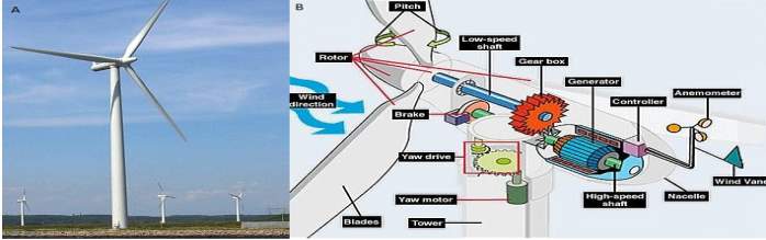
Design and operation
Wind turbines harnesses wind energy by using large turbine blades. When the wind comes across the blades, a torque is produced which turns a rotor, the rotor is connected to the main shaft, which in turn is attached to a gear box that steps up the speed to drive a generator that produces electrical energy.
Wind turbines can be susceptible to over spin in high winds, which could result in mechanical damage to the turbine.
To prevent over spin from occurring, failsafe’s have been incorporated into the design. An anemometer combined with a wind vane is fitted to the rear of the turbines nacelle, which is connected to a microprocessor that continually monitors both wind speed and direction. If the microprocessor detects elevated winds speeds that will push the turbine past the limits of the rated speed, it will send a signal to alter the pitch of the blades and keep the turbine within the range of its optimal generating speed.
If wind speed exceeds the ability of the blades pitch to control the speed of rotation, the microprocessor sends a signal to activate both the brakes that are applied to the turbines high-speed shaft and the yaw motor/drive that turns the turbine out of the direction of the head wind.
This system also ensures that the turbine is orientated in optimal position during low wind speed, to maximize the amount of time the turbine spends above the cut in speed.
Inverters are used to convert electrical energy generated by a turbine into usable AC electricity. Grid-tied inverters synchronize the frequency of the AC electricity produced to match the frequency of the AC electricity supplied by the National Grid, to enable surplus electrical energy to be exported and generates revenues via the feed in tariff scheme.
Turbine types
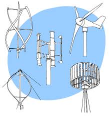
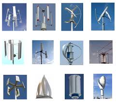
There are wide and varied range of wind turbine designs available in the market for both domestic and commercial applications:
- Pole mounted turbines are free standing structures that are erected in locations with suitably wind exposed position, domestic Pole mounted systems generally have a generating capacity of 4-15kW for domestic turbines and up to 1.5-3 MW for commercial turbines.
- Building mounted turbines are typically smaller than mast mounted systems and can be cited on the roofs tops of buildings where there is a suitable wind resource. Domestic building mounted systems generally have generating capability of circa 1kW to 5kW for domestic turbines and up to 5-500kW for commercial turbines.
- Vertical axis turbine: In this type of turbine the blades rotate on a axis parallel to the ground. This type of turbine is more stable than horizontal axis turbines and are virtually silent running (32dB at 6m) however this type of turbine is less efficient than vertical axis.
There are five types of blade design for vertical axis wind turbines:
- Savonius turbine
- Flapping Panel Turbine
- Darrieus turbine
- Giromill Turbine
- Gorlov Turbine
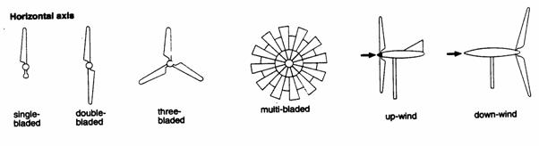
- Horizontal axis turbine: In this type of turbine the blades rotate on an axis perpendicular to the ground. horizontal axis turbines are the most widely used type of wind turbine, due high efficiency of the design, that produce more electricity from a given amount of wind than vertical access.
There are six types of blade design for horizontal axis wind turbines:
- Single bladed
- Double bladed
- Three bladed
- Multi-bladed
- Up-wind
- Down-wind
Location selection
When assessing the viability of a location for a wind turbine, it is vital to monitor and record local wind speeds. The amount of electrical energy that can be generated from a turbine is wholly dependent on local wind speeds.
The wind turbines location is crucial for maximising performance, there are multiple factors that contribute to the available wind speeds of a location:
- Location you are situated within the UK
- Obstruction the local vicinity such as buildings and trees causing a reduction in wind speeds and turbulence.
- The height level the turbine is situated above ground level is a major factor in the turbine’s ability to produce electrical energy, as impact of surface roughness on wind speeds which reduces disproportionally with height.
Wind power is proportional to the cube of the wind speed. The actual power delivered by wind turbine has to take into account for both the cutting speed and the rated speed of the turbine.
In in the range between the turbine cut in and rated wind speeds, the power output delivered by a turbine is generally proportional to the cube of the wind speed.
Cut in speed
If wind speeds are not sufficient for the turbine to reach its cut in speed the power output of a turbine will be zero. The cutting speed is the point at which turbine is rotating at a high enough angular velocity for power to be generated.
Rated speed
If wind speeds is at a higher velocity than the rated speed of the turbine, the power output falls flat after the rated speed is surpassed.


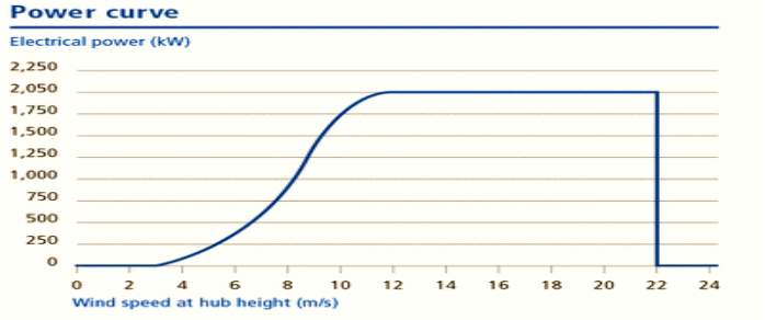
Cut in speed Rated speed
Turbine maintenance
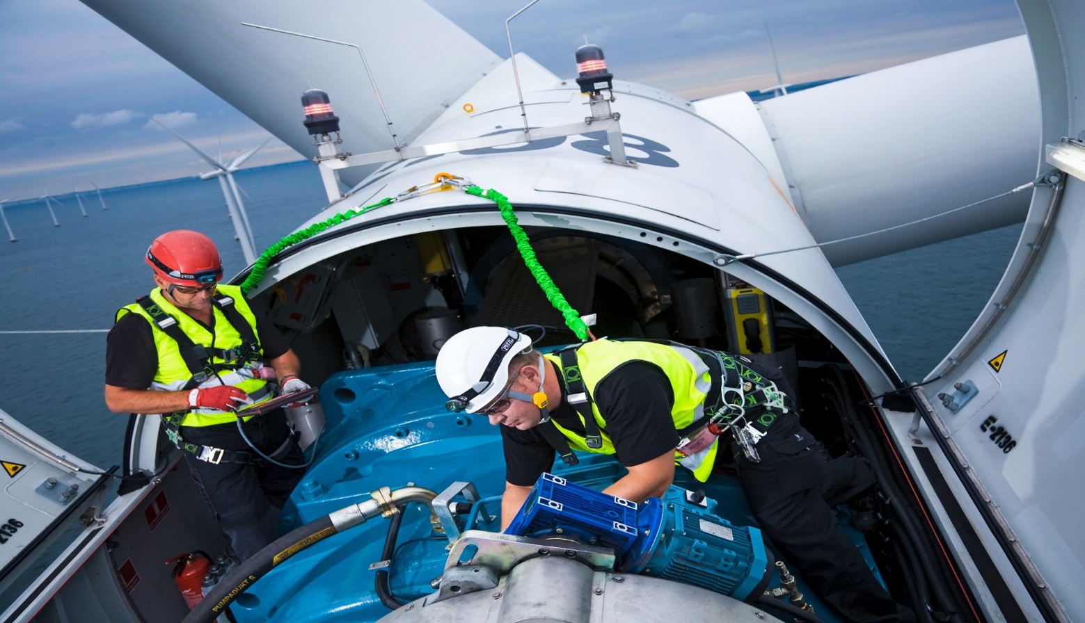
Wind turbines are relatively maintenance free, however are subjected to high levels of stress and strain and require to be maintenance checked by a wind turbine engineer every 3 to 4 years, at a cost of between £100 to £400 depending on turbine size and type.
A wind turbine that has been properly maintained can have a working life expectancy in excess of 20 years, however the turbines inverter has an expected operating lifespan of 15 years, at a cost of £1000-£3000 this needs to be factored into any maintenance and running cost projections.
Ground source heat pumps
The Earth stores massive amount of heat energy collected from both sun and Earth’s core itself.
Nearly 50% of the suns solar heat radiation is absorbed into the ground.
Ground temperatures are only affected by seasonal temperature variation down to a depth of approximately 15m, at this depth temperatures are equivalent to the annual mean air temperature, which is between 8 to 11 Celsius depending on location in the UK. Ground temperature rises at a rate of 2.6°C for every 100 metres in depth, as heat rises from the earth’s mantle.
A depth of 200 m the ground temperature in the UK are as high as 20°C depending on location.
Ground temperature in winter is at a higher level than air temperature and in summer the ground temperature is at a lower level than air temperature, a heat pump can utilise the differences in temperature and be used as a source of heating when it is cold and as air-conditioning/cooling when it’s hot.
System operation
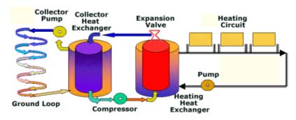
Ground source heat pumps uses a network of pipes buried in the ground that are looped back into the system to extract heat from the ground which can be used heat buildings and its hot water systems. A mixture of water and antifreeze absorbs heat from the ground as it is being pumped through the ground loop network, the returning warm water passes through a heat exchanger wheel the heat is absorbed into a refrigerant fluid, this causes the temperature of the refrigerant to rise to a level where it boils and turns into a gas, the gas is passed through a compressor which significantly raises the gases temperature. The higher temperatures gas is then passed through a second heat exchange coil removing the gases heat energy, turning the refrigerant back into liquid, the heat extracted from the gas is then fed into the building’s heating system where temperature can be increased by the building’s traditional heating system if required.
Heating systems supplied by a ground source heat pump, do not have to work as hard to meet the heat demands the supplied building, as the antifreeze mixture being supplied to the system has already been heated to a temperature of between 15 to 20°C and only requires to be heated by between 3 and 10°C. For every kilowatt of power put into the ground source heat pump supplied system, the system returns the equivalent of 3 kW of heat.
Ground loop area requirements
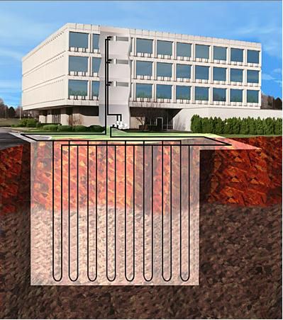
When planning a ground source heat pump system, ground loop network size requirements must be taken into account. The size or length of the ground loops are proportional to the size of the building that the system is to supply, the longer the ground loop, the more surface area the system has to absorb heat from the ground. Vertical boreholes can be drilled instead of horizontal trenches when site size is limited, however there is a significant increase in installation costs.

Ground source heat pumps on a domestic scale are generally categorised as permitted developments however it is advised to check with the local planning authority if planning permission is required. Larger scale vertical ground source heat pumps systems will require a geological survey to ascertain the composition of the proposed site. All underground utilities must be identified at the planning stage to assess whether the ground source is a viable option for the proposed site. A large number of utilities may be concealed underground including:
- Telecommunication lines
- Electricity distribution lines
- Gas lines
- Fibre-optics
- Storm drains network
- Water mains and wastewater pipes
System types and requirements
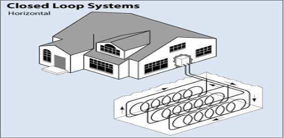
- Horizontal Ground Source Heat Pump system
- Ground source heating system array is laid in horizontal trenches, approximately 1-2 metres deep.
- Area requirements are dependent on the heating and cooling loads of the proposed building, depth of loop, moisture content of the soil, climate, and the heat pump efficiency. A typical building of hundred and 150 m² requires an area of between 300 m² and 700 m2
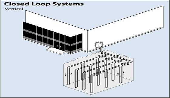
- Vertical Ground Source Heat Pump system
- A ground source loop array is inserted into vertical boreholes approximately 50-250m deep depending on ground composition and supplied buildings heating requirements.
- Boreholes must be set at least 6 m apart to prevent thermal leakage and efficiency losses and the least 5 m from any buildings.
- Vertical loops can provide 25 to 70 W per metre depending on ground composition.
- Planning permission must be granted when excavating a borehole.
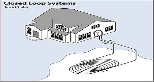
- Pond/Lake ground source heat pump system
- A supply loop pipe array is run underground from the supplied building to our body of water.
- Coils must be submerged to a minimum depth of 2.5m to negate the possibility of freezing.
- The water body must be of a sufficient volume, depth and quality to meet the requirements of pond or lake source heat pump.
- Pond/Lake systems benefit from low installation costs as minimal ground works are required.
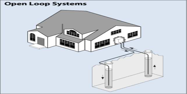
- Open-loop ground source heat pump
- Open-loop arrays utilise a surface body of water or well as heat exchange fluid that circulates directly through the ground source heat pump and returned to the ground through the well or softness discharge.
- This system must have an adequate source of clean water.
- Wells must have a minimum depth of 2.5m to negate the possibility of freezing
- Open-loop systems are subject to strict planning application procedures and regulations, regarding groundwater discharge.
Ground source heat pump maintenance

Ground source heat pump systems require minimal servicing and maintenance. The design life expectancy of grounds source heat pump is 20-25 years and are typically covered by a manufacturer’s warranty of 3 to 5 years.
Ground source heat pump systems as a whole is comprised of multiple components that require different levels of maintenance:
- Compressor
- Hermetically sealed unit that does not require maintenance.
- 20-25 years’ working life expectancy.
- Water pumps
- Servicing is recommended every 3 to 4 years.
- Pre-winter checks recommended.
- 10-20 years’ working Life expectancy.
- System electronics
- Pre-winter operational checks recommended.
- In excess of 25 years working life expectancy.
- External pipes and fittings
- pre-and post-winter leakage checks recommended.
- In excess of 40 years working life expectancy.
- Ground loop arrays
- Arrays are typically constructed of medium density polyurethane (M D P E) and requires no maintenance.
- In excess of 70 years working life expectancy.
- Ground array antifreeze solution
- Yearly sample checks for biocides and antifreeze levels recommended.
- Any anti-free samples removed from the system are classed as a hazardous substance and are required to be disposed of correctly according to HSE guidelines.
- Heating system
- Heating fluid inhibitor checks, to ensure the fluid is noncorrosive are recommended every 5-6 years.
- In excess of 30 years working life expectancy.
Ground source heat pump systems contains a refrigerant (F Gas), Refrigerant gases can cause serious harm to the environment, due to this all companies, engineers and technicians who are required to work on a circuit containing refrigerant gas, must be retrospectively certified under the EU’s 2006 F gas regulations.
Certification requirements and levels
- City and Guilds F gas.
- ODS regulations certificate.
- Building engineering services Association (BESA) F gas regulation accredited courses
Category 1:
- FG CAT 1
- Certificate holders are certified to carry out all activities including leakage, recovery, installation, maintenance and servicing.
Category2:
- FG CAT 2
- Certificate holders are certified to carry out all activities including leakage, recovery, installation, maintenance and servicing of systems containing less 3 kg of F gas.
Category 3:
- FG CAT 3
- Certificate holders are certified to carry out recovery of refrigerant gases in systems containing less 3 Kg of F gas.
Category 4:
- FG CAT 4
- Certificate holders are certified to carry out external refrigeration circuit leakage checks.
Air source heat pumps

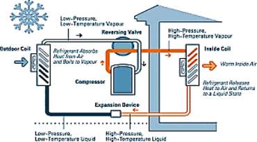
Air source heat pumps work on the same principle as a refrigerator only in reverse. In instead of heat being extracted from inside of a fridge and exported to a rooms atmosphere, heat is extracted from the air of the exterior of the building and imported into a building heating system.
Air source heat pumps systems work in both directions, heating in the winter and cooling the in the summer.
All air at a temperature above absolute zero contains heat energy. Air source heat pumps are a viable source of heat energy even in colder climates, the leading manufacturers air source heat pumps will extract useful heat energy in temperatures as low as -35°C.
System operation
Air source heat pumps draws air in from outside of the supplied building that passes over a heat exchange coil at low temperature, the low-temperature heat is absorbed into a refrigerant fluid, this raises the temperature of the refrigerant to a level where it boils and turns into a gas, the gas is passed through a compressor which significantly raises the gases temperature. The higher pressure and temperatures gas is then passed through a second heat exchange coil removing the gases heat energy, turning it back into liquid, the heat extracted from the refrigerant gas is fed into the building’s heating and hot water or vented here systems.
Air source heat pump types
1. Air to water heat pump system(s)
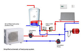
- The heat pump supplies hot water to the building’s wet heating system.
- Operates at optimal efficiency at lower temperatures than a standard boiler system and requires larger radiators or underfloor heating systems that distributes more heat at lower temperatures.
- The system requires longer periods of time than a standard boiler to heat internal spaces to the desired level.
2. Air to air heat pump system(s)

- The heat pump supplies warm air to buildings air ventilation heating system.
- Fans are required to circulate the warm air throughout interior space of the supplied building.
Air source heat pump requirements
- Suitable external location free from air flow obstructions.
- Supplied building must be efficiently insulated and draught proofed for an air source system to heat internal space effectively.
- Type of heating system
- Underfloor and warm air heating systems are most effective due to lower temperature output performance.
- Radiator based heating systems can be used, however are less effective. Larger radiators are required to be installed to optimise the lower temperature output.
Outdoor temperatures in excess of -35°C for system to operate, however a temperature above -10 is required for the system to have greater efficiency than traditional heating systems.
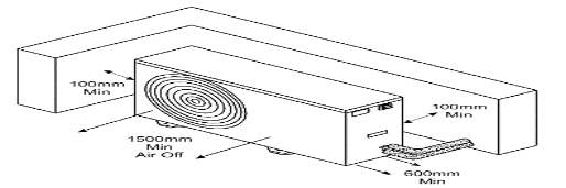
Air source heat pump must be installed a minimum of 100 mm from external walls of the supplied building and have no obstructions to airflow within a 1.5m vicinity of the air inlet vent.
Air source heat pump maintenance

Air source heat pumps require minimal servicing and maintenance. The design life expectancy of a correctly maintained air source heat pump is in excess of 20 years. Heat pumps themselves typically come with a manufacturer’s warranty of 3 to 10 years depending on manufacturer.
Recommended checks:
- Check air inlet vent is free of dirt, debris and blockages to airflow (annually).
- Check evaporator unit is free of dirt, debris and blockages to airflow (annually).
- Ensure objects haven’t been placed in the immediate vicinity of the external heat pump unit that may impede airflow.
- All Trees and bushes and shrubbery growing in the vicinity of air source heat pump air inlet will restrict airflow and should be removed (annually).
- Check pressure gauge level of the central heating system for drops in pressure (annually).

Servicing by a qualified installer of the air source heat pump system is recommended every 3 to 5 years. Any work being carried out on air source heat pump system must carried out by a qualified installer certified as competent under the EU’s 2006 F gas regulations.
Air source heat pump servicing will include:
- Expansion vessel charge pressure check and top up of required.
- Ensure all valves and freedom of movement and water stops valves are reset correctly.
- Inspect and clean heat pump circuit filter.
- Confirm primary heating system safety valve discharges correctly.
- Test concentration of antifreeze fluid mix and heating system and top up if required.
- Check primary heating system pressure is within parameters.
- Check primary heating system trapped there and release of required.
- Confirm correct fuse type and rating is installed on the electrical supply.
- Confirm collaboration and operation of temperature setting thermostats.
- Check operation of all motorised valves.
- Test your performance.
- Issue service certificate.
Air source heat pump systems that have refrigeration pipes situated externally to the supplied building required to be serviced annually by a refrigeration engineer.

Location information for Anniesland College
The Anniesland campus site of Glasgow Clyde college is situated on approximately 3.4 hectares of land with adjoining frontage to the south of Hatfield Drive and bounded by George Reith Avenue within the Anniesland area of Glasgow (National Grid reference to 55020E 6683340N).
The site comprises of a single to four-storey college complex, including games hall, workshops, classrooms, computer rooms, library, canteen and stores.
In the ground surrounding the complex are a large car park situated to East off of the site, with road access following round to the north and north-west area of the site which leads to enclosed Astroturf playing field and access to mechanical/electrical workshop, stores and further carparking.
The college complex structures have been erected with the four-storey main building situated to the north of the site adjoining Hatfield Drive with lower-level connected complex structures linked to the East portion of the main building wrapping around a central courtyard.
The main car park of the Anniesland campus has a capacity to cater for 200 vehicles, there is a regular and significant overspill of vehicles pertaining to the college into the surrounding residential area. Some animosity between local residents and vehicles owners connected with the college has arisen due to vehicles blocking access to private residences.
The complex itself a set within a higher demographic residential area. The campus is neighbouring a mix of detached and semi-detached villas. The raised position of the main college building, causes the building to overlook a row of 1930s built art deco residential apartments (Kelvin Court).
Solar shading
The raised elevation of the site coupled with a central location of the main college structures within the site, are such that buildings are un affected by shading from nearby structures, trees or vegetation. The low-level roof elevations of the college complex are orientated in a south facing direction and are unaffected by shading the by the main college four-storey structure.
Annual average wind speeds
Anniesland campus straddles the crest of the hill of Hatfield Drive. The ground level at the main entrance stands at approximately 41m above sea level. The main four-storey structure of the facility is approximately 17.45m in height.
The average wind speeds at ground level to 10 m in the area (1 km²) is 5.5 m/s. Due to the developed nature and mature trees, the area has a roughness class of 3.0 or roughness length of 0.4m (level of impedance to the flow of wind). Due to the raised amplitude of the site, moderately higher wind speeds than the area average can be expected.


The wind speeds at roof level of the four-storey main college building average 6.37m/s,
Location average annual temperature
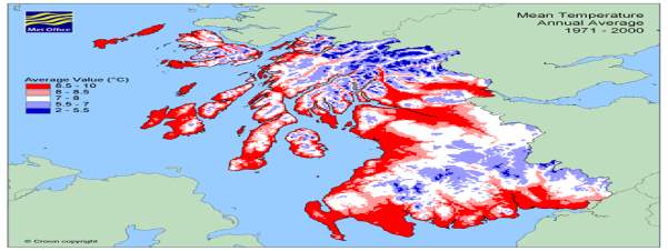
The mean average annual temperature of the campus location is 9.25°C.

The mean average maximum annual temperature of the campus location is 12.5°C.

The mean average minimum annual temperature for the campus location 5.5°C
Cite This Work
To export a reference to this article please select a referencing stye below:
Related Services
View all


Related Content
All TagsContent relating to: "Climate Change"
Climate change describes large changes in global or local weather patterns and global warming generally considered to be largely caused by an international increase in the use of fossil fuels from the mid-20th century onwards.
Related Articles

DMCA / Removal Request
If you are the original writer of this dissertation and no longer wish to have your work published on the UKDiss.com website then please: