Design of a Pneumatic Lifting Device
Info: 9211 words (37 pages) Dissertation
Published: 1st Sep 2021
Tagged: EngineeringTechnology
Abstract
The incentive of this project is to provide an alternative method for lifting heavy weight vehicles in the range of 2 tons by means of designing a pneumatic lifting device, where compressed air contrived through a compressor is the main source of providing lift to the vehicle. Furthermore, the objective of this final year project is to add further functionality to existing heavy weight lifters, by allowing manoeuvrability of the lifted vehicle. In this project, the design of the pneumatic heavy weight lifter is thoroughly explained, along with the specifications and scope. The selection of various parts for the design has been made with the product feasibility towards its functionality in mind. It is vital to acknowledge that the selected parts have been able to meet with the design requirements.
Keywords: DESIGN OF A PNEUMATIC ; LIFTING ; DEVICE ;
CONTENTS
LIST OF FIGURES
LIST OF TABLES
LIST OF SYMBOLS
CHAPTER 1 INTRODUCTION
CHAPTER 2 LITERATURE REVIEW
CHAPTER 3 METHODOLOGY
CHAPTER 4 RESULTS AND DISCUSSION
CHAPTER 5 CONCLUSION AND RECOMMENDATION
REFERENCES
APPENDIX A
APPENDIX B
APPENDIX C
LIST OF SYMBOLS
RPM Rotary Pneumatic Motor
PR Pressure Regulator
DSR Double Stage Regulator
PA Pneumatic Actuator
MTP Momentum Transfer Pump
EP Entrapment Pump
SPS Sealed Pressure Sensor
CHAPTER 1 INTRODUCTION
1.1 Introduction
This chapter delivers a general introduction on the topic studied. The research background and problem statement are concisely discussed in the first section. The following section lists the project objective and scope of project. The final section in this chapter presents the thesis organization and outline.
1.2 Background
In order to enhance the transfer of equipment so as to facilitate various vital procedures necessary for human development such as large scale construction, and manufacturing on large scale along with the ease of maintenance to both vehicles, and other machines, the proper designed equipment must be available in order to assure the ease and efficiency in the transfer, loading, and off loading of large weights. Therefore, this project aims to aid in such operations by designing a product that can meet with these vital requirements, which is to design a pneumatic lifting device capable to lifting weights up-to 2 tons. Hence, this is to be attained through the utilization of various software required or the design such as Pro/E along with the research undertaken on the matter, and knowledge gained from various literature reviews. This thesis thoroughly explores project undertaking, and explains the various phases of design that comprised of three phases. The first phase consists of searching the relevant information and various principles that go into designing devices capable of carrying excessively large weights, with regard to suitable design structure, materials used, and engineering dynamics that come into play in order to come up with a preliminary design. The second phase consists of utilizing the acquired knowledge and information gained from the preliminary design in order to attain an effective detailed design, along with the required analysis in order to prove it capability of successfully lifting weights of upto 2 metric tons.
1.3 Objective
The objective of this project is to successfully design a Pneumatic lifting device that is capable of efficiently and safely lift loads of up-to 2 metric tons and shift the load around. The accomplished design should also be capable of lifting a vehicle off the ground in order to carry out underbody repairs. Furthermore, a detailed stress analysis is to be carried out on the simulation software used in order to determine the safety factor of the design, thereby providing a product in which safe systems of work is developed and used for all lifting operations. The risk assessment of the design work should take into account the working environment, geographical location etc where the equipment is to be used.
1.4 Scope
For this project, the design for heavy weight pneumatic lifter must be able to comply with the constraints set forward for this experiment. Hence, the scope of research for pneumatic lifter Is divided into the following three sub-categories:

Pneumatic Lifter
Figure 1.1 : Scope of research for pneumatic lifter
1.4.1 Selection of Pneumatic Motor
The pneumatic motor acts as the main power source capable of providing lift to the design. In this section, a pneumatic motor with precise specifications is selected for the required design. During the conceptual design phase, it was found that a pneumatic motor that is capable of providing sufficient power would suffice for the overall lightweight body of the design. A massive motor was eliminated during the conceptual analysis phase as heavy designs were omitted for a more efficient, more practical compact design that requires a lot less powerful motor, hence adding to the practicality of the design. The selected motor however, should be capable of operating with high loading, and for the sake of safety, it should be able of successfully lifting a weight above the required 2 tons.
1.4.2 Selection of Lifting Mechanism
For this criterion, a unique alternative to the various hydraulic heavy weight lifting devices was opted for. This was due to the fact that compressed air is a lot more unpredictable compared to uncompressible hydraulic fluid. 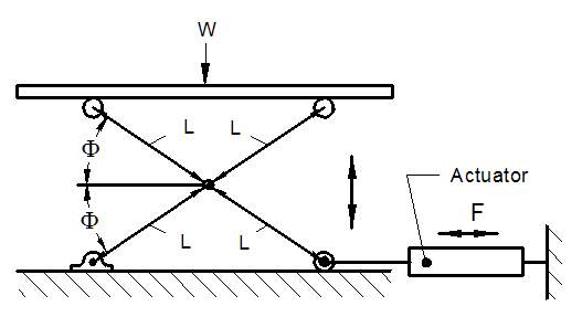
Figure 1.2 : Scissors Lift
Therefore, the scissors concept of lift was opted for due to it’s ability of providing safety latches at every point of lift, thereby acting as an automatic brake in case of pneumatic motor failure and helping to eliminate dangerous or fatal accidents in the operation of this machinery [1].
1.4.3 Manoeuvrability
The obstacle of providing manoeuvrability to the design was overcome by the installation of heavy duty castors which was made possible after omitting heavy based designs that required excessive amount of energy for movement, to a more compact design that allows locomotion by the least exertion of energy by operator.
1.5 Organization of Thesis
This thesis is organized in the following order:
- Chapter 1
A brief overview of pneumatic lifters in general and need for design of pneumatic lifter capable of lifting a 2-ton vehicle for undercarriage maintenance.
- Chapter 2
A comprehensive summary on the various types of heavy weight lifting devices and mechanisms.
- Chapter 3
Description of the design methodology and various parameters applied to designing the pneumatic heavyweight lifter.
- Chapter 4
Contains explanation for the base calculation of the design and precise analysis of constructed parts of the pneumatic lifter
- Chapter 5
Summarizes the result of the design selection and concludes the design of the pneumatic lifter. This chapter also provides suggestion on future development of the current design.
CHAPTER 2 LITERATURE REVIEW
2.1 Introduction
This chapter discusses in detail, the present pneumatic technology available. The first section provides an overview of the functionality of pneumatics in general, along with their various applications. Following sections describe the various principles relating to pneumatics, along with the benefits of using such systems. Furthermore, a comprehensive research on various types of pneumatic motors, pistons, and sensors is clearly illustrated here. Pneumatic systems in fixed installations, such as factories, utilize compressed air since compressing atmospheric air can be a source of sustainable supply. The air regularly has moisture removed, and a small measure of oil is supplemented at the compressor in order to avoid corrosion and provide lubrication to the numerous mechanical constituents. One perceptible and valuable benefit in utilizing pneumatic-power for factory applications is that operators need not worry about poisonous leakages, due to the fact that the gas is ordinarily pure air. However, compressed gases that present an asphyxiation hazard, such as nitrogen—often referred to as OFN (oxygen-free nitrogen), could be used be smaller stand alone systems. Every compressed gas besides air is considered as a suffocation hazard—including nitrogen, which makes up to approximately 78% of air. Compressed oxygen (approx. 22% of air) would not lead to suffocation, but it is not utilized in pneumatically powered devices due to it being more expensive, a fire risk and offering no performance improvement over air. Handy pneumatic tools and small vehicles, the likes of Robot Wars machines are generally powered by compressed carbon dioxide, since containers that are devised to hold it such as fire extinguishers are easily accessible, and the phase change between liquid and gas makes it possible to obtain a larger volume of compressed gas from a lighter container than what is required by compressed air. Carbon dioxide is a suffocating agent and can be a freezing hazard if vented unfittingly. Pneumatic Lifters predominantly use pneumatic cylinders of low friction as source of lifting power and are capable of providing a cost effective solution to many lifting applications. Compared with vacuum lifting devices, pneumatic lifts are normally more suited to manual handling operations, which require precise or controlled pick and place movements, such as vehicle line-side operations in automotive plants.
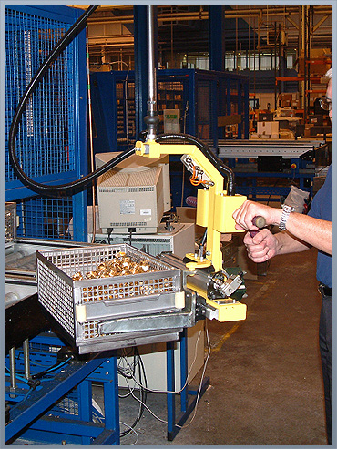
Figure 2.1: Pneumatic lifter
Pneumatic Lifters may utilize numerous pneumatic cylinder arrangements as the key power source, which would provide substantial lifting capabilities. Guided pneumatic lifters allow a solid mounting platform for tooling and the option of powered rotation in one or more axes. This design makes for particularly good drum handling equipment; where controlled movements prove beneficial to operators engaged in drum pouring or barrel tipping operations.
2.2 Pneumatic Actuators
A PA is a device that transforms energy (compressed air) into motorized movement. This motion can be either linear or rotary, depending on the type of pneumatic actuator used. The following are listed examples of pneumatic actuators:
- Rotary actuators
- Tie rod cylinders
- Artificial Pneumatic muscles
- Rod less actuators with mechanical linkage
- Rod less actuators with magnetic linkage
- Grippers
- Specialty actuators that combine rotary and linear motion—frequently used for clamping operations
- Vacuum generators
A PA primarily contains a tube, ports and pistons. A seal keeps the air in the upper portion of the tube, thereby allowing air pressure to force the diaphragm downward, covers the piston moving the piston underneath, which in turn moves the valve stem that is linked to the internal parts of the actuator [2]. Depending on the type of action required, pneumatic actuators may have only one spot for a signal input. Valves need only slight pressure to function and normally double or triple the input force, therefore, the output pressure is directly proportional to the size of the piston. Thus, a larger piston can also be suitable if air supply is low, allowing the same forces with less input. A small pneumatic valve is capable of effortlessly lifting a vehicle (weighing approx. 500 kg) by applying only a 100 KPa input. However, the subsequent forces necessary of the stem would be too excessive and would eventually lead the valve stem to fail. 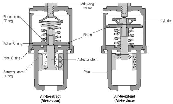
Figure 2.2: Pneumatic Actuator
This pressure is transferred to the valve stem, which is hooked up to either the valve plug, butterfly valve etc. Larger forces are required in high pressure or high flow pipelines to allow the valve to overcome these forces, and allow it to move the valves moving parts to control the material flowing inside. Valves input pressure is the "control signal." This can come from a variety of measuring devices, and each different pressure is a different set point for a valve [3]. A typical standard signal is 20–100 kPa. For example, a valve could be controlling the pressure in a vessel which has a constant out-flow, and a varied in-flow (varied by the actuator and valve). A pressure transmitter will monitor the pressure in the vessel and transmit a signal from 20–100 kPa. 20 kPas indicates and absence of pressure, where as 100 kPa indicates a full range pressure (varies with the transmitter’s calibration). With the rise in pressure within the vessel, an equal rise in the output of the transmitter occurs, this increase in pressure is sent to the valve, a result of which the valve forces a downward stroke, and proceeds to closing the valve, thereby reducing the pressure in the vessel as excess pressure is evacuated through the out flow. This process is called a direct acting process.
2.3 Pneumatic cylinder
Pneumatic cylinders (air cylinders) are mechanical devices that utilize the power retrieved from the compressed gas in order to yield a force in a reciprocating linear motion. As with hydraulic cylinders, pneumatic cylinders utilize the stored potential energy of a fluid, in this case compressed air, and convert it into kinetic energy as the air expands in an attempt to reach atmospheric pressure. This air expansion forces a piston to move in the desired direction. The piston is a disc or cylinder, and the piston rod transfers the force it develops to the object that is to be moved. Engineers prefer to use pneumatics sometime because they are quieter, cleaner, and do not require large amounts of space for fluid storage [4]. 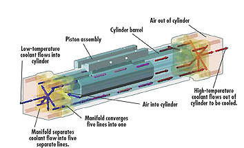
Figure 2.3: Pneumatic Actuator
Because the operating fluid is a gas, leakage from a pneumatic cylinder will not drip out and contaminate the surroundings, making pneumatics more desirable where cleanliness is a requirement. For example, in the mechanical puppets of the Disney Tiki Room, pneumatics is used to prevent fluid from dripping onto people below the puppets.
2.4 Pneumatic Motor
A pneumatic motor (compressed air engine) is a motor that achieves mechanical work thru the expansion of compressed air. Pneumatic motors ideally utilize either rotary or linear motion for the conversion of compressed air to mechanical work. This linear motion is attained either from a piston or diaphragm actuator, where as the rotary motion is supplied by either a pneumatic vane motor or a pneumatic piston motor [5]. 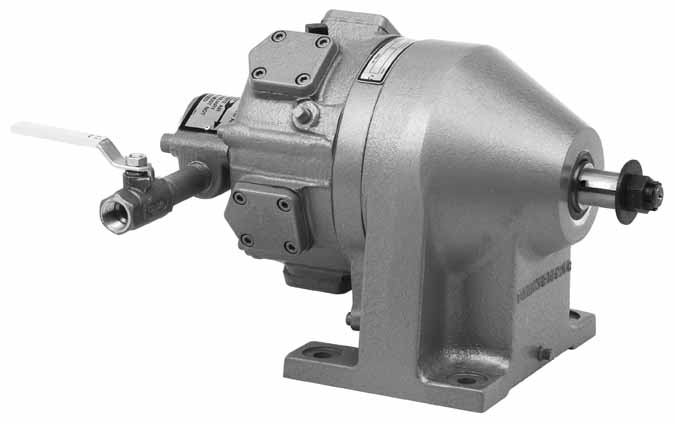
Figure 2.4: Radial Piston
Pneumatic Motor Over the past two centuries, Pneumatics has been present in a number of forms that ranged in size, from miniature turbines to engines capable of conjuring several hundred horsepower. A variety of compressed air engines increase their performance either by heating the incoming air, or the engine itself. Pneumatic have been extremely successful in the hand-held tool industry, and there have been constant attempts in expanding their use in the transportation industry. However, in order to be considered as a viable option in the transportation industry, these motors must overcome various inadequacies.
2.4.1 Linear Pneumatic Motors
So as to utilize compressed air in order to attain a motion that is linear in nature, it is uncommon that an arrangement of pistons to be use. Air that is compressed is then pumped into a cavity that is airtight and contains the shaft of the piston. Likewise, a coiled spring that surrounds the shaft is located within the cavity and keeps the compartment in an open position, in the event air is not fed into the chamber. While air is pumped into the cavity, the force that is exerted on the spring is overcome by the force acting on the shaft of the piston. An increase of pressure occurs when the amount of air allowed into the cavity is increased as well. This leads the piston to travel down the cavity [6]. Once its full length is attained, air pressure is discharged from the cavity, thereby allowing the spring to finish the cycle by means of shutting off the cavity in order to return to its initial position. 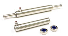
Figure 2.5: Linear Pneumatic Motor
Hydraulic systems primarily use piston motors, which are very similar to hydraulic pumps, except for the fact that they are utilized for translating hydraulic energy into mechanical energy. Piston motors are often used in series of two, three, four, five, or six cylinders that are enclosed in a housing.
2.4.2 Rotary Pneumatic Motors
RPM (rotary vane motors), utilizes air in order to drive rotational motion to a shaft. The rotating motion is attained by means of an instrument known as a slotted rotor that is fixed on a drive shaft. Every rotor gap has a freely slipping rectangular vane that is built-in. Depending on the design of the motor, air pressure, cam action, or springs are used in order to extend the vanes to the housing walls. The motor feeds compressed air in order to push the vanes, so as to attain a rotational motion of the central shaft [7]. The speeds of rotation can range from 100 to approx. 26,000 rpm, depending on the air pressure.
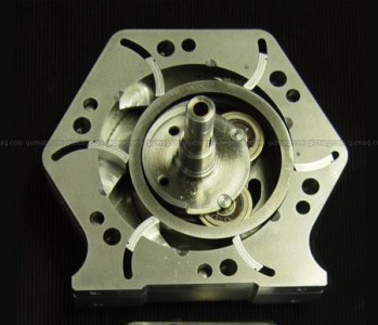
Figure 2.6: Rotary Vane Motor
These motors are generally applied to operate immense natural gas or diesel or engines. Stored energy in the form of compressed air, nitrogen or natural gas enters the sealed motor chamber and exerts pressure against the vanes of a rotor. This causes the rotor to turn at high speed. Reduction gears are used due to the fact that the engine flywheel requires a great deal of torque to start the engine. These reduction gears generate elevated levels of torque, with only a small amount of energy entered, which provides for adequate torque to be produced by the engine flywheel whilst being absorbed by the air motor’s pinion gear.
2.5 Pressure Regulators
The main function of PR is to match the flow of gas throughout the regulator to the demand for gas placed upon the system. If the load flow decreases, then the regulator flow must decrease also. If the load flow increases, then the regulator flow must increase in order to keep the controlled pressure from decreasing due to a shortage of gas in the pressure system [8]. A PR contains a restricting element, a loading element, and a measuring element:
- The restricting element is a type of valve that can either be a globe valve, butterfly valve, poppet valve, or any other form of valve, which is capable of operating as a variable restriction to the flow.
- The loading element applies the needed force to the restricting element. It can be any number of things such as a weight, a spring, a piston actuator, or more commonly the diaphragm actuator in combination with a spring.
- The measuring element determines when the inlet flow is equal to the outlet flow. The diaphragm is often used as a measuring element because it can also serve as a combine element.
In the pictured single-stage regulator, a force balance is used on the diaphragm to control a poppet valve in order to regulate pressure. With no inlet pressure, the spring above the diaphragm pushes it down on the poppet valve, holding it open. Once inlet pressure is introduced, the open poppet allows flow to the diaphragm and pressure in the upper chamber increases until the diaphragm is pushed upward against the spring, causing the poppet to reduce flow, finally stopping further increase of pressure. By adjusting the top screw, the downward pressure on the diaphragm can be increased, requiring more pressure in the upper chamber to maintain equilibrium. In this way, the outlet pressure of the regulator is controlled.
2.5.1 Single Stage Regulator
As the spindle pertaining to the cylinder is gradually opened, high pressure gas from the cylinder travels into the regulator via an inlet valve, and enters the body of regulator that is inhibited by the needle valve. With the increase of pressure within the regulator, both the valve as well as the diaphragm proceed to close the valve and stop any gas from entering the regulator. The opening is fixed with a pressure gauge that indicates the working pressure on the blowpipe. While the gas is being drawn from the channel, the pressure within the regulator body falls. The diaphragm is pressed back by the spring and the valve opens, allowing additional gas in from the cylinder [9]. Thus, the pressure within the body depends on the pressure of springs, which can be attuned by means of a regulator knob.
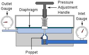
Figure 2.7: One stage Regulator
2.5.2 Double Stage Regulator
A DSR contains two regulators that work to reducing the pressure gradually in a two-stage process [10]. The present is the first stage, in which the cylinder pressure is reduced to a transitional stage; gas at that pressure passes into the second stage. The gas now emerges at a pressure (working pressure) set by the pressure adjusting control knob attached to the diaphragm. Two stage regulators have two safety valves, so that if there is any excess pressure there will be no explosion. A major objection to the single stage regulator is the need for frequent torch adjustment. If the cylinder pressure falls the regulator pressure likewise drops, thereby necessitating torch adjustment. In the two stage regulator, there is automatic compensation for any drop in the cylinder pressure. Single stage regulator may be used with pipelines and cylinders. Two stage regulators are used with cylinder and manifolds.
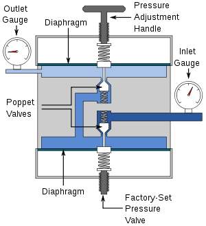
Figure 2.8: Two Stage Regulator
2.6 Pressure Sensors
A pressure sensor is a device that measures pressure, characteristically of either liquid or gas. Pressure (usually expressed as force per unit area) is generally defined as the amount of force necessary to prevent the expansion of a liquid. Pressure sensor act as transducers and generate signals as a result of the enforced pressure. Pressure sensors are widely used in everyday applications for monitoring and controlling purposes. These sensors could also be used to measure other parameters such as altitude, water level and speed. Pressure sensors are also referred to as pressure transmitters, transducers, senders, and pressure indicators. There could be a drastic variation in the design, technology and performance of pressure sensors. A moderate assessment is that there might be over 50 technologies, as well as 300 companies that specialize in manufacturing pressure sensors worldwide. Certain pressure sensors are designed to measure the changes of pressure in extremely high speeds. Such pressure sensors find wide use in various applications such as the measurement of combustion pressure within a gas turbine. These sensors are generally produced from piezoelectric constituents such as quartz. Certain pressure sensors, similar to those integrated into traffic cameras, operate in a binary mode, which means that when pressure is supplied to a pressure sensor, the sensor in turn, work to either complete or discontinue a circuit. These sets of sensors are also identified as a pressure switch.
2.7 Types of Pressure Measurement
Pressure sensors can be referred to in terms range of temperature operation, range of pressure measurement, and most significantly the type of pressure they measure. Pressure sensors are variously named according to their function. However, the same technology may be used under different names [11].
2.7.1 Absolute pressure sensor
This sensor measures the pressure in relation to perfect vacuum.
2.7.2 Gauge pressure sensor
This sensor determines the pressure in relation to atmospheric pressure. One example of this apparatus is a tire pressure gauge, which when indicating zero, the pressure it is measuring is identical to the ambient pressure.
2.7.3 Vacuum pressure sensor
A vacuum pressure sensor refers to a sensor, which measures pressures below atmospheric pressure, thereby depicting the difference between low pressure and atmospheric pressure. However, it may also be used to portray a sensor that measures low pressure compared to a perfect vacuum (i.e. absolute pressure).
2.7.4 Differential pressure sensor
Differential pressure sensor is a sensor that determines the difference between two pressures, of which; one is linked to every side of the sensor. These sensors are required to measure numerous properties, such as a drop in pressure across either air or oil filters, level of a fluid (by evaluating the pressure over and beneath the liquid) or flow rates (by measuring the alteration in pressure across a restraint). The majority of pressure sensors are classified as differential pressure sensors; A gauge pressure sensor is simply a differential pressure sensor where one surface is open to the ambient atmosphere.
2.7.5 Sealed pressure sensor
An SPS is similar to a gauge pressure sensor excluding the fact that it measures the relative pressure in relation to a fixed pressure, instead of the ambient atmospheric pressure (which fluctuates according to the position and the climate).
2.8 History Of Pneumatics
The first example of a pneumatics application can be tracked to as far back as the first century, when the ancient mathematician of Greek origin, best known as the Hero of Alexandria, wrote about his ingenious inventions that were run by either wind or steam. However, none of his considerations revealed intentions of operating pneumatic devices for transporting objects. On the other hand, German physicist Otto von Guericke (1602-1686) moved a little further by inventing the vacuum pump, a device capable of drawing either air or gas from any vessel it is attached to. He illustrated that vacuum pump air pressure could be utilized in order to separate pairs of copper enclosures called hemispheres.
2.8.1 Capsule Transportation
The capsule was first invented in 1886 and allowed people to transport items by placing them in a container. People in Victorian England were the first known to use capsule pipelines to transmit telegrams from one telegraph station to another.
2.8.2 Postal Systems
Scottish engineer William Murdoch (1754 to 1839) was the first to apply pneumatics to postal services, but there is little evidence that he went further than suggesting the transmission of letters and packages through pneumatic tubes. American merchant John Wanamaker (1838 to 1922) installed a pneumatic system in the United States Post Office when he was postmaster general and in department stores to transport money from one section to the other.
2.8.3 Public Transportation
Pneumatics was also applied to public transportation. A notable example is the efforts of American inventor Alfred Beach (1826 to 1896). In 1867, Beach demonstrated a pipe able to transport a handful of passengers, giving birth to the pneumatic subway line. However, the line only lasted for a few months, terminated after Beach was unable to gain permission to extend the distance of the subway.
2.9 Vacuum Pumps
A vacuum pump is a device that removes gas molecules from a sealed volume in order to leave behind a partial vacuum. The first vacuum pump was invented in 1650 by Otto von Guericke, and was preceded by the suction pump, which dates to antiquity. Positive displacement pumps are the most effective for low vacuums. Momentum transfer pumps in conjunction with one or two positive displacement pumps are the most common configuration used to achieve high vacuums. In this configuration the positive displacement pump serves two purposes. First it obtains a rough vacuum in the vessel being evacuated before the momentum transfer pump can be used to obtain the high vacuum, as momentum transfer pumps cannot start pumping at atmospheric pressures. Second the positive displacement pump backs up the momentum transfer pump by evacuating to low vacuum the accumulation of displaced molecules in the high vacuum pump. Entrapment pumps can be added to reach ultrahigh vacuums, but they require periodic regeneration of the surfaces that trap air molecules or ions. Due to this requirement their available operational time can be unacceptably short in low and high vacuums, thus limiting their use to ultrahigh vacuums. Pumps also differ in details like manufacturing tolerances, sealing material, pressure, flow, admission or no admission of oil vapour, service intervals, reliability, tolerance to dust, tolerance to chemicals, tolerance to liquids and vibration. Vacuum Pumps can be broadly categorized according to three techniques:
2.9.1 Positive displacement Pumps
These pumps use a mechanism to repeatedly expand a cavity, allow gases to flow in from the chamber, seal off the cavity, and exhaust it to the atmosphere.
2.9.2 Momentum transfer Pumps
MTPs, also called molecular pumps, use high-speed jets of dense fluid or high speed rotating blades to knock gas molecules out of the chamber
2.9.3 Entrapment pumps
EPs are responsible for capturing gases in a solid or adsorbed state. This includes cryopumps, getters, and ion pumps.
2.10 Comparison of Pneumatics to Hydraulics
Both pneumatics and hydraulics are applications of fluid power. Pneumatics uses an easily compressible gas such as air or a suitable pure gas—while hydraulics uses relatively incompressible liquid media such as oil. Most industrial pneumatic applications use pressures of about 80 to 100 pounds per square inch (550 to 690 kPa). Hydraulics applications commonly use from 1,000 to 5,000 psi (6.9 to 34 MPa), but specialized applications may exceed 10,000 psi (69 MPa).Advantages of pneumatics:
- Simplicity of design and control—Machines are easily designed using standard cylinders and other components, and operate via simple on-off control.
- Reliability—Pneumatic systems generally have long operating lives and require little maintenance. Because gas is compressible, Equipment is less subject to shock damage. Gas absorbs excessive force, whereas fluid in hydraulics directly transfers force. Compressed gas can be stored, so machines still run for a while if electrical power is lost.
- Safety—There is a very low chance of fire compared to hydraulic oil. Machines are usually overload safe.
CHAPTER 3 METHODOLOGY
3.1 Introduction
This chapter explains the proposed design, sizing and dimensioning of parts and load calculations. The following sections discuss in detail the optimization of capacitor size, capacitor allocation and switching of capacitor. The general procedure derived from proposed method is summarized at last. The following flowchart describes the chronological steps followed to achieve the objectives of the project. First of all, literature review is carried out in order to gain a clearer background with respects to previous research carried out on similar topics. Following this initial yet crucial step in methodology, a comprehensive concept generation stage is carried out in order to produce viable options for meeting the objectives set forth. Following this phase was the concept evaluation phase, in which the various pros and cons of each concept are scientifically evaluated in order to produce a successful design. Having set forth an established final design, an extended market research is then carried out in order to integrate various essential items into the design that are necessary for attaining a sustainable and efficient lift mechanism along with selecting suitable material to establish locomotion of the final product.
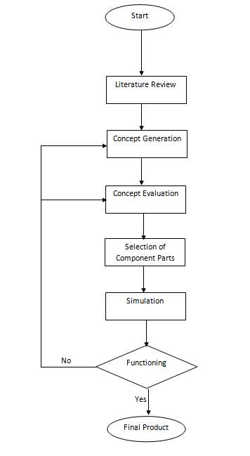
Figure 3.1: Methodology Flowchart
3.2 Concept Generation
3.2.1 Concept 1:
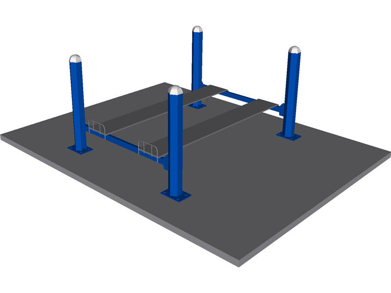
Figure 3.2: First Concept
Figure 3.2 illustrates the first designed concept that is based on the standard heavy weight hydraulic lifters currently present in all maintenance shops, the reason why this concept generated great promise was due to the ability of installing a lift mechanism through four independent pillars, allowing for a more promising result. However, due to the fact that no provisions were made for motion, the above design required an urgent revision.
3.2.2 Concept 2:
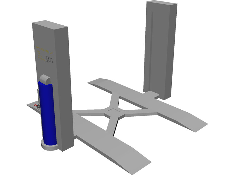
Figure 3.3: Second Concept
Figure 3.3 depicts the second generated concept, which offers an alternative lifting mechanism to the first concept, and offers numerous benefits to the original concept due to its more compact nature. Here, the lifting mechanism is attained by means of compressors that supply compressed air to two individual pillars. However, a major hindrance in the form of inability to provide a steady safe form of motion led to this concept being dropped.
3.2.3 Concept 3:
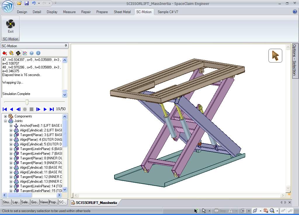
Figure 3.4: Third Concept
Figure 3.4 illustrates the third and final concept generated in the conceptual design phase. This was originally the most promising concept due to a superior safety factor, and the ability of providing lift through an actuator placed either at the base, centre point or both. However, this concept was omitted due to the inability of this design to meet with a vital requirement of the objectives, which is to offer a work area underneath the lifted vehicle.
3.3 PNEUMATIC MOTOR:
The key objective of the design is to lift a body of weight 2000 N. Therefore in order to figure the type of pneumatic motor that is capable of achieving this out of the various motors available (i.e.Gerotor air motors, milling motors, motor/engine starters, piston motors, turbine motors, and vane motors), it is vital to first determine the required torque to lift a vehicle of the stated weight, which can be calculated as follows, assuming a lifting acceleration of 1 m/s2, a motor radius of 0.3 m and the cylindrical motor to be of 30 kg weight [13]. T= FR sin T= I Tnet= 1/2MPRP2P Which would imply that the net torque for the motor would be: Tnet= (Fmotor- T1)Rd= MdRd2 Fmotor= Md + T1 Which implies that: [tex]/tau_{motor} = F_{motor} R _motor weight = 1895Nm Therefore, the most suitable pneumatic motor for the design could be vane motor, a result of which vane motor model 68-S169 K was chosen for the design due to it having the ideal required properties that are listed in this table as follows: 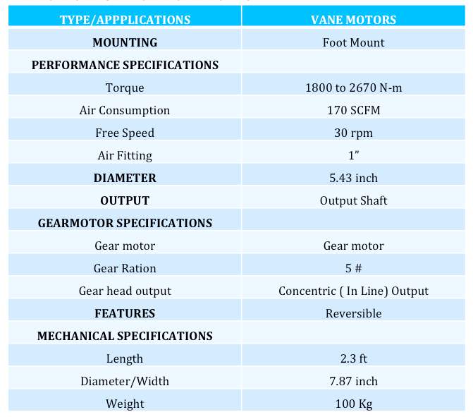
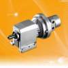
Figure 3.2: Vane Motor
3.4 LOCOMOTION
- Top Mount
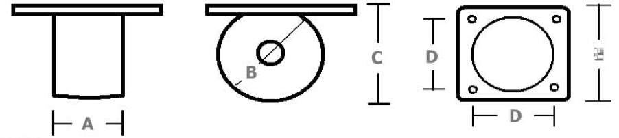
- Side Mount
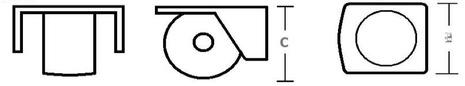
Figure 3.3 Top and side Mounts of Castor Wheels
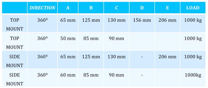
The ability of the pneumatic lifter to move the vehicle into any location is made possible by the simple installation of the above heavy duty castors that have multiple functionality, with the wheels made out of cast nylon. Hence allowing it the strength to handle excessive loads while allowing any personnel to move a two ton mass by the application of very little amount of force. The following diagram indicates the rotation capabilities of castors installed in respective positions along with the load capacity for each castor wheel.
CHAPTER 4 RESULTS AND DISCUSSION
4.1 Introduction
This chapter aims at offering a comprehensive oversight of the finalized design with respect to the conclusive dimensions of the various components, along with the results attained from the stress analysis test, which would attain whether or not the final product would be capable of withstanding the weight set forth of 2 tons. Further discussions with regards to the results attained are also provided.
4.2 Design Parameters
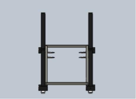
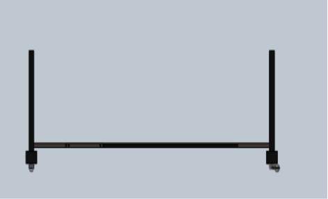
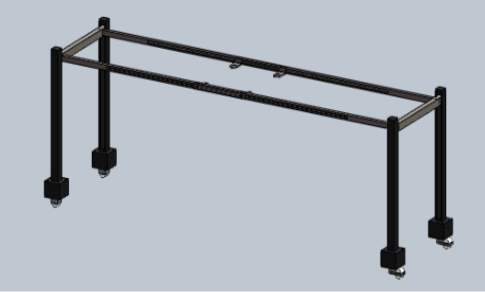
Figure 4.1 illustrates the finalized design, which after the comprehensive concept evaluation phase, was largely influenced by the first concept, however various altercations were made so as to allow horizontal motion to the lifted vehicle. It’s designed to lift the vehicle to a distance of 7 feet, thereby complying with the requirements of the objectives, and allowing for sufficient room for a mechanic to perform maintenance work on the undercarriage. Figure 4.2 on the other hand, depicts the stress strain analysis carried out on the final design where as figures (4.4- 4.8), offer detailed depiction of the numerous component parts that formulate the design. The reason why this concept generated great promise was due to the ability of installing a lift mechanism through four independent pillars, allowing for a more promising result. This designed concept that is based on the standard heavy weight hydraulic lifters currently present in all maintenance shops.
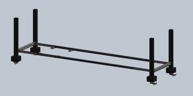
Figure 4.1: Final Design
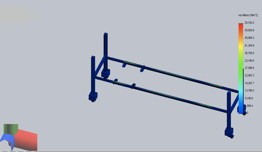 Figure 4.2 : Stress Strain Analysis
4.3 Component Parts: 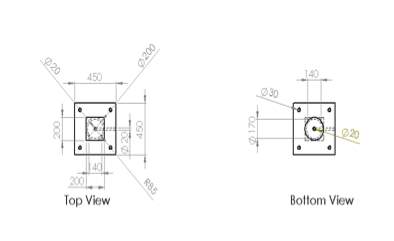
Figure 4.3: Pole Design 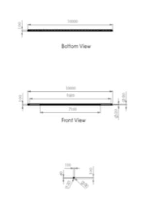
Figure 4.4: Upper Support 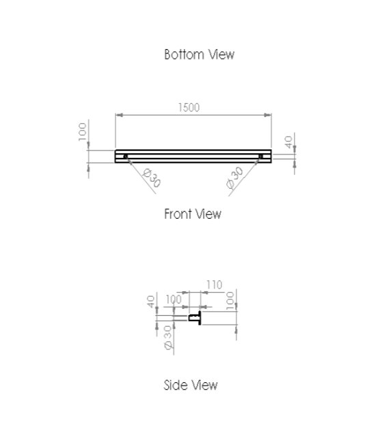
Figure 4.5: Upper Support (Secondary Part)
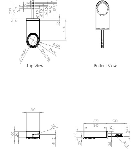
Figure 4.6: support for the car (part 1) 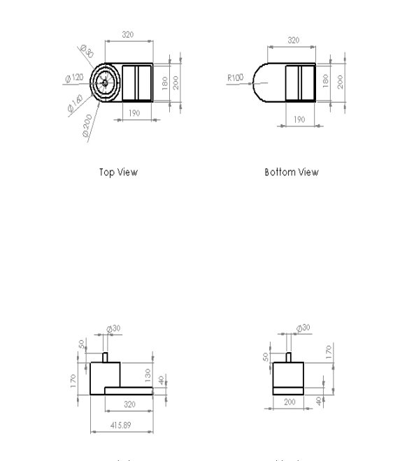
Figure 4.7: support for the car (part 2) 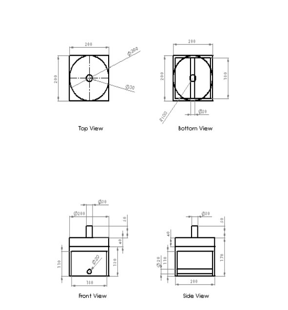
Figure 4.8: Locomotion Component
4.4 Final Design Parameters:
Table 4.1: Specifications of Pneumatic Lifter
| SPECIFICATIONS | PNEUMATIC LIFTER |
| RETRACTED HEIGHT OF BASE | 0.115 m |
| ELEVATED HEIGHT | 2.133 m |
| LENGTH | 4 m |
| WIDTH | 1.1 m |
| POWER SOURCE | Air Compressor |
| MAXIMUM LIFT LOAD | Approx. 3,263 kg |
| OVERALL PROJECTED WEIGHT | 500 kg |
| WHEEL TURNING CIRCLE | 3600 |
| REQUIRED AIR PRESSURE | 100-150 psi |
| DIRECTION OF LOAD | Front or Rear entry |
| ONBOARD ELECTRONICS | None |
Table 4.1 highlights the general parameters of the pneumatic lifter, whereby it is illustrated that the source of power for the design is derived via an air compressor that provides an air pressure ranging from 100-150 psi. It also illustrates that the turning circle of cast wheels installed in the design are capable of rotating in 3600.
Table 4.2: Specifications of Vane Motors

Table 4.2 gives a comprehensive depiction of the vane motor that is selected for the design. These paramters were attained from current industry standard pneumatic motors that are available in the present market. With the ability of providing torque above 1800 N-m, and with an air fitting of 1”, this specific vane motor is capaable of providing the required force for lift, by usingstandard pressure vessels.
Table 4.3: Specification of castors
4.5 Calculation of Time and Velocity:
4.5.1 Time Required to Lift the Vehicle:
From the selected vane motors specifications, it is clear that it would be able of providing a uniform acceleration of 0.025 m/s2. As the distance required for the vehicle to travel is 7 feet (approx. 2.1336 meters), the time required to lift the vehicle could be calculated from the following equation: S= ut + 1/2(at2) 2.1336= ½(0.25)(t2) Therefore, T= 13 seconds
4.5.2 Time required for Horizontal Motion:
In order to calculate the time required for horizontal motion, a slight altercation is made to the above equation, in the form of distance travelled which is 4 meters. S= ut + ½(at2) 4= ½(0.025)(t2) Hence, T = 18 seconds
4.5.3 Velocity Provided By Vane Motor:
The velocity with which the vehicle is lifted is determined by utilizing essential data gained from the above equation, where the time required to lift the vehicle is ascertained to be 13 seconds. Therefore, the lift velocity is as follows: V = u + at V = 0.025(13) Hence, the lift velocity is given as: V= 0.325 m/s
4.6 DISCUSSION:
The above figures illustrate in detail the finalized design, which is largely bound on the first original concept that has been heavily modified in order to provide both vertical as well as horizontal motion to the lifted vehicle. A comprehensive market research that was carried out revealed that the required lift for safely lifting the required weight set forth of 2 tons, could be adequately adhered to by the use of two sets of vane motors in each pillar, that would be capable of providing up-to 2670 N-m of torque. The reason why the original design was heavily modified in order to formulate the final product is that, expansive research revealed that for the sake of safety when it comes to the handling of heavy weight items in the aforementioned weight, a predetermined path of motion was essential so as to formulate a safe work area surrounding the lifted vehicle, and offering practicality by allowing motion through different areas so as to ease the process of most essential requirements of lifting a vehicle such as removing the engine, gearbox, and the carrying out of undercarriage maintenance in specified areas. In order to completely adhere to the requirements of the design objectives, measures for absolute mobility were integrated into the design by the installation of heavy duty industrial castors made out of cast nylon, each capable of withstanding a weight exceeding 1 ton, while stress strain analysis indicated that the proposed design should be capable of withstanding a force of 32000 N/m2 which equals approximately 3.263 tons, thereby surpassing the required value. From the calculations carried out based on information attained from the technical specifications of materials selected, it was then found that the time required to lift a vehicle weighing 2 tons, a total time of 13 seconds, at a uniform velocity of 0.326 m/s.
CHAPTER 5 CONCLUSION AND RECOMMENDATION
5.1 Conclusion
After adhering to the strict design discipline set forth in the methodology phase of the project, the objectives of this project were met in a truly satisfactory manner, thereby designing one of the world’s first pneumatic lifter capable of safely and efficiently carrying a car weighing up-to 2 tons, in order to carry out undercarriage maintenance. In current industry, such heavy weight duty is reserved for hydraulics rather than pneumatics, due to the predictable and un-compressible property of liquids. The various dangers associated with the utilization of compressed air for such applications is that compressed air could be very unpredictable, and if a direct feeding mechanism was considered for the design, additional impracticalities would have been faced in the form of excessive heat generated in harnessing such vast amounts of pressure. However, such hindrances were avoided by the integration of pneumatic motors into the design, whereby even at low speeds, sufficient torque could be generated to provide lift for the vehicle. In the concept generation phase of the project, various pneumatic motors were considered for the lifting mechanism (such as gerotor air motors, milling motors, motor/engine starters, piston motors, turbine motors, and vane motors), out of which, the vane motor was selected due to it being able to produce a required force of 2670 N-m. Thus four vane motors installed into the design would be able to safely lift any vehicle in excess of 2 tons. This coupled with the fact, that it’s inlet air fitting is 1 inch, and requires an air pressure ranging from 100-150 psi in order to produce the stated torque. This means that this design would bring forth radical practicality, by its ability to be directly integrated into any current work shop that utilizes standard pressure vessels for the use of bolt removal in tires. In terms of mobility, the finalized design is capable of providing two forms of motion. The first form allows for enhanced safety, by adhering to the requirement of mobility through the use of a predetermined path. Here, the vane motors are capable of lifting a vehicle in a time span of only 13 seconds, with a constant velocity of 0.325 m/s. However, in the case of boundary-less motion, two sets of specialized castors made of cast nylon were integrated into the final design due to its ability to rotate in 3600, while being able to support a weight of 1 ton each. Arguably the biggest innovation in this design is its breakthrough application of vane motors in order to vent the various dangers associated with handling high pressure gases, whereby only small pressure is required to generate the required amount of torque necessary to lift the vehicle. Thereby, getting rid of the issue of the un-predictable nature of compressed gases. Thus, the wide spread use of this design in the field of car maintenance could possibly revolutionize this industry, by allowing for a work environment that is much cleaner as air could simply be vented out of the machine where as hydraulic require constant rigorous maintenance, while evacuating the hydraulic fluid.
5.2 Recommendations
Due to the uniqueness of this design, and it being one of the first attempts at providing a viable alternative to current hydraulic heavy weight lifters, there are a variety of recommendations for future development of the current pneumatic lifter. The first is to providing a more efficient design by means of installing a single feed in mechanism for torque, which would allow for a design that is more compact, and hence, cheaper to operate. Furthermore, the application of stronger, more advanced materials, along with a more developed feed in mechanism for torque, could offer numerous benefits by providing a lifting capability to cars weighing in excess of 5 tons. Enhanced safety standards and controllability of the heavy weight lifter could also be enhanced by the integration of electronic sensors and components into the design, which would provide an automated operation. The current design has been developed according the realization of the latest technical expertise available with the regards to pneumatic devices. However, it is expected that the current design would be capable of coping with future development in this field, with the advent of more advanced pneumatic motors, whereby a simple exchange of the motor could offer superior performance. It is therefore most recommended that any addition to the current design should be done, with the perspective of future performance of design.
REFERENCES
[1] Tian Hongyu & Zhang Ziyi, Design and simulation Based on Pro/E for a Hydraulic Lift Platform in Scissors type, International Workshop on Automobile, Power and Energy, 2011.
[2] A.Mehmood, S. Laghrouche & M.El Bagdouri, Modellig identification and simulation of pneumatic actuator for VGT system, Laboratoire S.E.T., Universite de Technologie de Belfort-Montbeliard, Belfort, France.
[3] Sebastian Butefish, Volker Seidmann & Stephanus Buttegnbach, Novel micro-pneumatic actuator for MEMS, Institute for Microtechnology, Technical University of Braunschweig, Alte Salzdahlumer Str. 203, 38124 Braunschweig, Germany, 2002.
[4] Ming-Chang Shih & Shy-l Tseng, Identification and position control of a servo pneumatic cylinder, Control Engineering Practice, 1995.
[5]Air motors. Retrieved 10 October 2012, from http://www.hydraulicspneumatics. com/200/TechZone/FluidPowerAcces/Article/True/6422/TechZone-FluidPowerAcces
[6] Technology zone-air motor. Retrieved 23 October 2012, from http://www. hydraulicspneumatics.com/200/TechZone/FluidPowerAcces/Article/True/6422/TechZone-FluidPowerAcces
[7] H.M Mahgoub & I.A. Craighead, Development of a microprocessor based control system for a pneumatic rotary actuator, Mechatronics, Volume 5, Issue 5, August 1995.
[8] V. Tesar, Extremely simple pressure regulator-computation studies, Chemical Engineering Journal, Volume 155, December 2009.
[9] One Stage Regulators. Retrieved 24October 2012, from http://www.scott- marrin .com/one_stage_regulators.htm
[10] Two Stage Regulators. Retrieved 24 October 2012, from http://www.scottma -rrin.com/two_stage_regulators.htm
[11] Jin Li, Hao Liu, Yuzxiu Wang, Lingling Shi & Fengxia he, Development of a low cost portable pressure measurement system using for garment design, Measurement, Volume 45, October 2012.
[12] M. Zagnoni, A. Golfarelli, S. Callegari, A. Tamelli & V. Bonora, A non-invasive capacitive sensor strip for aerodynamic pressure measurement, Sensors and Actuator A: Physical, Volumes 123-124, September 2005.
[13] J. Naranjo, E. Kussul & G. Ascanio, A new pneumatic vanes motor, Mechatronics, Volume 20, Issue 3, April 2010.
APPENDIX A
APPENDIX B
APPENDIX C
Cite This Work
To export a reference to this article please select a referencing stye below:
Related Services
View all


Related Content
All TagsContent relating to: "Technology"
Technology can be described as the use of scientific and advanced knowledge to meet the requirements of humans. Technology is continuously developing, and is used in almost all aspects of life.
Related Articles

DMCA / Removal Request
If you are the original writer of this dissertation and no longer wish to have your work published on the UKDiss.com website then please: