Changing Phone Mode from Silent to Loud via Text
Info: 14201 words (57 pages) Dissertation
Published: 11th Dec 2019
Tagged: TechnologyMobile Phones
ABSTRACT
In real life, fogetting the things is very common tendency by every human being. Few times, we may keep the things in our premises and we may forget about it. Same thing may happen with our mobiles phones too. We may forget/lose our phone in our near premises. We may think that, we can just make call to that phone and find the location. But if the phone is in silent mode what can we do? How can we find the mobile?.In that situation this project is very helpful. In this project, just by sending a single customized message to our phone we are changing our phone mode to ringing or silent or vibrate whatever we want
1.INTRODUCTION
- PROBLEM DEFINITION
One of the fastest growing industries now a day is mobile industry. There are many competitors in this area who are doing research and development on new platforms & user experience. One such technology is Android from Google which is supported for many manufactured phones. These phones are described as next Generation mobiles [As described by Google]. In real life, forgetting the things is very common human tendency..sometimes we may kept the things in our premises and we may forget about it.Same thing can be happened with our mobiles.We may forget/lose our phone in our near premises.We may think that,we can just make call to that phone and find the location.but if the phone is in silent mode what we can do? how can we find the mobile location?
In that situation this project is very helpful.In this project,just by sending a single message to our phone we are changing our phone mode to ringing or silent or vibrate whatever we want.
. This application supports 2.3 version of android frame work.
1.2 EXISTING SYSTEM:
In the existing system there is no service like changing our phone upon receiving security code as a message previously. If any user unexpectedly forget his phone in his near premises and its in silent mode. As of now in android mobiles there is no such system which changes our phone mode to whtever we want i.e.silent or ring or vibrate.if user wants to change his mode,only manually he can change the mode of the phonewhich is not possible when phone is missing.
1.3 PROPOSED SYSTEM
To overcome the drawback in the existing System we are going to develop this project which makes the mobile set back to ringing mode.
Diagramatic Representation:
when secure code is send to mobile then


Advantages:
- Giving the security codes for each mode(silent,Ring,Vibrate)
- Using that security code ,changing our phone mode to silent,ring or vibrate.
1.3.1 Modules
RingMode on android is having the following modules
- Setting the SecurityCode
- Changing the phone mode
1.Setting the SecurityCode:
In this module,we need to set security code for each mode i.e. silent,ring and vibrate.By default values will be silent for silent mode,ring for Ring mode and vibrate for vibrate mode.User can also change this values.
2.Changing the phone mode:
Whatever the codes you have given,just send that code as amessage to your phone.then your phone will be changed to that particular mode what u have sent.
1.4 SCOPE OF PROJECT
One of the fastest growing industries is mobile industry. There are many competitors in this area who are doing research and development on new platforms & user experience. One such technology is Android from Google which is supported for Google phones. These phones are described as next Generation mobiles [As described by Google]. Developing application for such mobile phones using the open source android SDK is quite interesting. This makes the application call history quite easy, efficient, flexible and economic.
2. SYSTEM REQUIREMENTS
2.1 Hardware requirements:
- Operating System : Pentium based systems with a minimum of p4
- RAM : 1GB (minimum)
- Hard Disk : 40GB or above
2.2 Software requirements
- IDE: Eclipse or Android Studio
- OS: Windows XP and above
- SDK: Android 4.0.3 and above
- CODE BEHIND: Java and xml
3. SYSTEM STUDY
FEASIBILITY STUDY
The feasibility of the project is analyzed in this phase and business proposal is put forth with a very general plan for the project and some cost estimates. During system analysis the feasibility study of the proposed system is to be carried out. This is to ensure that the proposed system is not a burden to the company. For feasibility analysis, some understanding of the major requirements for the system is essential.
Three key considerations involved in the feasibility analysis are
- ECONOMICAL FEASIBILITY
- TECHNICAL FEASIBILITY
- SOCIAL FEASIBILITY
3.1 ECONOMICAL FEASIBILITY
This study is carried out to check the economic impact that the system will have on the organization. The amount of fund that the company can pour into the research and development of the system is limited. The expenditures must be justified. Thus the developed system as well within the budget and this was achieved because most of the technologies used are freely available. Only the customized products had to be purchased.
3.2 TECHNICAL FEASIBILITY
This study is carried out to check the technical feasibility, that is, the technical requirements of the system. Any system developed must not have a high demand on the available technical resources. This will lead to high demands on the available technical resources. This will lead to high demands being placed on the client. The developed system must have a modest requirement, as only minimal or null changes are required for implementing this system.
3.3 SOCIAL FEASIBILITY
The aspect of study is to check the level of acceptance of the system by the user. This includes the process of training the user to use the system efficiently. The user must not feel threatened by the system, instead must accept it as a necessity. The level of acceptance by the users solely depends on the methods that are employed to educate the user about the system and to make him familiar with it. His level of confidence must be raised so that he is also able to make some constructive criticism, which is welcomed, as he is the final user of the system.
4. SOFTWARE ENVIRONMENT
4.1. JAVA
Java is an object-oriented language, and is very similar to C++. Java is simplified to eliminate language features that cause common programming errors. Java source code files are compiled into a format called byte code, which can then be executed by a Java interpreter.Features being
- Platform Independent
The programs written on one platform can run on any platform provided the platform must have the JVM.
- Portable
The feature Write-once-run-anywhere makes the java language portable provided that the system must have interpreter for the JVM.
- Simple
Programs are easy to write and debug because java does not use the pointers explicitly. It also has the automatic memory allocation and de-allocation system.
- Multithreaded
Multithreading means a single program having different threads executing independently at the same time.
- Robust
Java has the strong memory allocation and automatic garbage collection mechanism. It provides the powerful exception handling and type checking mechanism as compare to other programming languages.
- Object Oriented
To be an Object Oriented language, any language must follow at least the four characteristics.
- Inheritance
- Encapsulation
- Polymorphism
- Dynamic binding
- Distributed
The widely used protocols like HTTP and FTP are developed in java. Internet programmers can call functions on these protocols and can get access to the files from any remote machine on the internet rather than writing codes on their local system.
- Secure
All the programs in java are run under an area known as the sand box. Security manager determines the accessibility options of a class like reading and writing a file to the local disk.
- High Performance
In the beginning interpretation of byte code resulted in slow performance but the advance version of JVM uses the adaptive and just in time compilation technique that improves the performance.
- Integrated
Java is an interpreted language as well. Programs run directly from the source code.
4.2ANDROID
Android is a software stack for mobile devices that includes an operating system, middleware and key applications. The android SDK provides the tools and APIs necessary to begin developing applications on the Android platform using the Java programming language.
Features
Application framework enabling reuse and replacement of components
Dalvik virtual machine optimized for mobile devices
Integrated browser based on the open source WebKit engine
Optimized graphics powered by a custom 2D graphics library; 3D graphics based on the OpenGL ES 1.0 specification (hardware acceleration optional)
SQLite for structured data storage
Media support for common audio, video, and still image formats (MPEG4, H.264, MP3, AAC, AMR, JPG, PNG, GIF)
GSM Telephony (hardware dependent)
Bluetooth, EDGE, 3G, and WiFi (hardware dependent)
Camera, GPS, compass, and accelerometer (hardware dependent)
Rich development environment including a device emulator, tools for debugging, memory and performance profiling, and a plugin for the Eclipse IDE
Android application
Developers have full access to the same framework APIs used by the core applications. The application architecture is designed to simplify the reuse of components; any application can publish its capabilities and any other application may then make use of those capabilities (subject to security constraints enforced by the framework). This same mechanism allows components to be replaced by the user.
Libraries
Android includes a set of C/C++ libraries used by various components of the Android system. These capabilities are exposed to developers through the Android application framework. Some of the core libraries are listed below:
System C library – a BSD-derived implementation of the standard C system library (libc), tuned for embedded Linux-based devices
Media Libraries – based on PacketVideo’s OpenCORE; the libraries support playback and recording of many popular audio and video formats, as well as static image files, including MPEG4, H.264, MP3, AAC, AMR, JPG, and PNG
Surface Manager – manages access to the display subsystem and seamlessly composites 2D and 3D graphic layers from multiple applications
LibWebCore – a modern web browser engine which powers both the Android browser and an embeddable web view
SGL – the underlying 2D graphics engine
3D libraries – an implementation based on OpenGL ES 1.0 APIs; the libraries use either hardware 3D acceleration (where available) or the included, highly optimized 3D software rasterizer
FreeType – bitmap and vector font rendering
SQLite – a powerful and lightweight relational database engine available to all applications
Android Runtime
Android includes a set of core libraries that provides most of the functionality available in the core libraries of the Java programming language.
Every Android application runs in its own process, with its own instance of the Dalvik virtual machine. Dalvik has been written so that a device can run multiple VMs efficiently. The Dalvik VM executes files in the Dalvik Executable format which is optimized for minimal memory footprint. The VM is register-based, and runs classes compiled by a Java language compiler that have been transformed into the .dex format by the included “dx” tool.
The Dalvik VM relies on the Linux kernel for underlying functionality such as threading and low-level memory management.
an Android code editor that helps you write valid XML for your Android manifest and resource files.
It will even export your project into a signed APK, which can be distributed to users.
To begin developing Android applications in the Eclipse IDE with ADT, you first need to download the Eclipse IDE and then download and install the ADT plug-in. To do so, follow the steps given in Installing the ADT Plug-in.
Developing in eclipse with ADT:
The Android Development Tools (ADT) plug-in for Eclipse adds powerful extensions to the Eclipse integrated development environment. It allows you to create and debug Android applications easier and faster. If you use Eclipse, the ADT plug-in gives you an incredible boost in developing Android applications:
It gives you access to other Android development tools from inside the Eclipse IDE. For example, ADT lets you access the many capabilities of the DDMS tool: take screenshots, manage port-forwarding, set breakpoints, and view thread and process information directly from Eclipse.
It provides a New Project Wizard, which helps you quickly create and set up all of the basic files you’ll need for a new Android application.
It automates and simplifies the process of building your Android application.
It provides
Android is a software stack for mobile devices that includes an operating system, middleware and key applications. The android SDK provides the tools and APIs necessary to begin developing applications on the Android platform using the Java programming language.
The Android SDK includes a comprehensive set of development tools. These include a debugger, libraries, a handset emulator (based on QEMU), documentation, sample code, and tutorials. Currently supported development platforms include x86-architecture computers running Linux (any modern desktop Linux distribution), Mac OS X 10.4.8 or later, Windows XP or Vista. The officially supported integrated development environment (IDE) is Eclipse (3.2 or later) using the Android Development Tools (ADT) Plug in, though developers may use any text editor to edit Java and XML files then use command line tools to create, build and debug Android application
4.2.1 About Native code:
Libraries written in C and other languages can be compiled to ARM native code and installed, but the Native Development Kit is not yet officially supported by Google. Native classes can be called from Java code running under the Dalvik VM using the System. Load Library call, which is part of the standard Android Java classes.
4.2.2 Creating an android project
The ADT plug-in provides a New Project Wizard that you can use to quickly create a new Android project (or a project from existing code). To create a new project:
- Select File > New > Project.
- Select Android > Android Project, and click Next.
- Select the contents for the project:
- Enter a Project Name. This will be the name of the folder where your project is created.
- Under Contents, select Create new project in workspace. Select your project workspace location.
- Under Target, select an Android target to be used as the project’s Build Target. The Build Target specifies which Android platform you’d like your application built against.
- Unless you know that you’ll be using new APIs introduced in the latest SDK, you should select a target with the lowest platform version possible, such as Android 1.1.
- Under Properties, fill in all necessary fields :
Enter an Application name. This is the human-readable title for your application — the name that will appear on the Android device.
- Enter a Package name. This is the package namespace (following the same rules as for packages in the Java programming language) where all your source code will reside.
- Select Create Activity (optional, of course, but common) and enter a name for your main Activity class.
- Enter a Min SDK Version. This is an integer that indicates the minimum API Level required to properly run your application. Entering this here automatically sets the min Sdk Version attribute in the <uses-sdk> of your Android Manifest file. If you’re unsure of the appropriate API Level to use, copy the API Level listed for the Build Target you selected in the Target tab.
- Click Finish.
Once you complete the New Project Wizard, ADT creates the following folders and files in your new project:
src/
Includes your stub Activity Java file. All other Java files for your application go here.
<Android Version>/ (e.g., Android 1.1/)
Includes the android.jar file that your application will build against. This is determined by the build target that you have chosen in the New Project Wizard.
gen/
This contains the Java files generated by ADT, such as your R.java file and interfaces created from AIDL files.
assets/
This is empty. You can use it to store raw asset files. See Resources and Assets.
res/
A folder for your application resources, such as drawable files, layout files, string values, etc. See Resources and Assets.
AndroidManifest.xml
The Android Manifest for your project. See The AndroidManifest.xml File.
default.properties
This file contains project settings, such as the build target. This files is integral to the project, as such, it should be maintained in a Source Revision Control system. It should never be edited manually — to edit project properties, right-click the project folder and select “Properties”.
4.2.3 To create an AVD with the AVD manager:
- Select Window > Android SDK and AVD Manager, or click the Android SDK and AVD Manager icon (a black device) in the Eclipse toolbar.
- In the Virtual Devices panel, you’ll see a list of existing AVDs. Click New to create a new AVD.
- Fill in the details for the AVD.
- Give it a name, a platform target, an SD card image (optional), and a skin (HVGA is default).
- Click Create AVD.
When you first run a project as an Android Application, ADT will automatically create a run configuration. The default run configuration will launch the default project Activity and use automatic target mode for device selection (with no preferred AVD).
4.2.4 To Create or Modify a Launch Configuration
Follow these steps as appropriate for your Eclipse version:
- Open the run configuration manager.
- In Eclipse 3.3 ,select Run > Open Run Dialog (or Open Debug Dialog)
- In Eclipse 3.4 (Ganymede), select Run > Run Configurations (or Debug Configurations)
- Expand the Android Application item and create a new configuration or open an existing one.
Android has a concept of shared preferences using which application preferences data can be stored persistently. That means the data or state won’t be lost until the application is uninstalled. The preferences data can be stored as key/value pairs and are available across all the Activities of the given application or can also be restricted to a particular Activity.
4.3 SHARED PREFERENCES
Using the SharedPreferences interface implementations we can store persistent sets of data in the filesystem. The data will be available across application restarts or even device stop/start. Consider it as a small cave to hold your app’s data mostly related to settings and user preferences. Anything that is slightly more complicated like relational data should still go into the sqlite database or media files into the filesystem.
SharedPreferences can be used to store any (and only) primitive data types – booleans, floats, ints, longs and strings – that’ll persist across user sessions (user closes the app and re-opens it). To determine what type of data to store, just think of anything that might require caching for quick usage like username, logged in state, email, high score or level in a game, gender (or other profile info), app-related settings, etc.
Shared Preferences can be stored at 2 levels – activity or application. To get a SharedPreferences object for your activity or application in order to start storing, retrieving and updating data there are two methods:
- getSharedPreferences() – Application-wide preferences file identified by the name passed to it as the first argument.
- getPreferences() – Activity-level preferences object where no name is specified as there will be only one file for an Activity.
Here’s how the first one is used:
| 1 | SharedPreferences pref = getSharedPreferences(“MyPrefs”, Context.MODE_PRIVATE); |
You can store as many shared preferences as you want for your application and all of them will keep on getting saved in the XML file named MyPrefs which is usually located at/data/data/[package name]/shared_prefs/MyPrefs.xml. You can browse that in the File Explorer in the DDMS view or if your device is rooted then go ahead and explore it in $ adb shell.
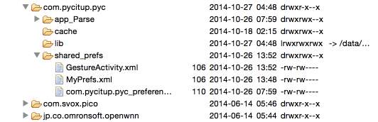
The image shows my app specific data (including shared preferences) in DDMS. com.pycitup.pyc is my application’s package name.
In case you don’t want to provide a name for app-wide shared preferences then we can usePackageManager.getDefaultSharedPreferences() (not included in the list of methods above) which uses a default name behind the scenes which is a concatenation of the package name and the string _preferences. Hence the file path will be something like/data/data/com.package.name/shared_prefs/com.package.name_preferences.xml. This is how you use it:
| 1 | SharedPreferences pref = PreferenceManager.getDefaultSharedPreferences(this); |
The activity-level method version has to be used like this:
| 1 | SharedPreferences pref = getPreferences(Context.MODE_PRIVATE); |
This version will save its data in /data/data/[package name]/shared_prefs/[Activity Name].xml.
If you notice we passed an option called Context.MODE_PRIVATE (can also pass just MODE_PRIVATE if in an activity or the integer 0) which basically means that the created shared preferences file will be accessible by the calling application only.
Now let’s go through how to write and read preferences.
Storing Preferences
Once you’ve decided whether you want application preferences or activity one, then you’ll start storing data into it. Once you’ve a valid SharedPreferences object you call edit() method on it to fetch a SharedPreferences.Editor object whose public method will allow us to start writing data to the file. To store primitive data it has various methods like putBoolean(), putFloat(), putInt(),putLong() and putString().
the commit() method to commit our changes. There’s another method to do the same which is apply() but that is asynchronous and won’t report failures.
Retrieving Preferences
Fetching the preferences is done directly on the SharedPreferences object. SoSharedPreferences.Editor is not required. There are several `get` methods for this job likegetBoolean(), getFloat(), getInt(), getLong() and getString(). All of them accept two arguments where the first is the name of the key while the second non-optional one is the default value to return if the preference does not exists (is undefined).
| 1
2 3 4 5 6 7 |
SharedPreferences pref = getSharedPreferences(“MyPrefs”, Context.MODE_PRIVATE);
String username = pref.getString(“username”, “”); boolean logged_in = String.valueOf(pref.getBoolean(“logged_in”, false); Log.d(TAG, username); Log.d(TAG, String.valueOf(logged_in)); |
The code logged CodeTheory and false in separate lines.
Deleting Preferences
Deleting a particular preference is super simple. Just call the remove() method and commit your changes.
| 1
2 3 4 5 |
// Remove a particular key
pref.remove(“username”); // Commit changes pref.commit(); |
You can also clear() the entire remaining preferences from your storage.
Usage
You might be wondering when to use this data storage option. A few cases that I can think off the bat are:
- Game’s high score and current level.
- Persisting user session post login in your application where the session data contains username, email, gender, etc.
- Applications like WhatsApp have their Settings/Preferences section where you can set the notification ring tone or status message and other app-specific options to modify the behaviour or features. This can be achieved with SharedPreferences easily.
Android Preference APIs/Objects
When building a full-fledged settings/preferences section for the user in your app (somewhat similar to the Android’s Settings app), instead of building the user interface with your own custom View objects and then wiring up the functionality by writing some backend logic in the Activity class, we can use Preference objects in conjunction with PreferenceActivity to quickly build the user interface. Along with that the other major advantage of this approach is that, saving preferences is done behind the scenes using Shared Preferences and the integration of the UI with the updated value to set the correct state of various controls (checkbox for example) is also handled automatically. Apart from that this entire framework has its own simple APIs for quick customizations.
The comprehensive Android settings guide has all the information with regards to this.
Conclusion
So we explored the Shared Preferences data storage option which eases some sort of caching by storing super simple and quick key/value pairs (in XML files behind the scenes). Remember for more complicated data like relational data or files there are other options like saving in sqlite or the filesystem.
Users are pretty smart: if your program is power-hungry, you can count on them noticing. The only thing you can be sure of at that point is that your program won’t stay installed.
5. CODING
The following xml is used for userinterface to set the securecodes for sound,ring and vibrate modes.
mainapp.xml
<?xml version=”1.0″ encoding=”utf-8″?>
<RelativeLayout xmlns_android=”http://schemas.android.com/apk/res/android”
android:orientation=”vertical” android_layout_width=”match_parent”
android:layout_height=”match_parent”
android:id=”@+id/relativeid3″>
<ImageView
android:layout_width=”match_parent”
android:layout_height=”match_parent”
android:id=”@+id/imageView”
android:layout_alignParentTop=”true”
android:background=”@drawable/nnbr”
android:layout_alignParentRight=”true”
android:layout_alignParentEnd=”true” />
<TextView
android:id=”@+id/soundtxt”
android:layout_width=”wrap_content”
android:layout_height=”wrap_content”
android:text=”Sound”
android:textSize=”25dp”
android:layout_below=”@+id/text”
android:layout_centerHorizontal=”true” />
<EditText
android:id=”@+id/codeet”
android:layout_width=”wrap_content”
android:layout_height=”wrap_content”
android:ems=”10″
android:password=”false”
android:layout_below=”@+id/soundtxt”
android:layout_centerHorizontal=”true”
android:layout_marginTop=”37dp” />
<Button
android:id=”@+id/codesavebtn”
android:layout_width=”wrap_content”
android:layout_height=”wrap_content”
android:onClick=”SaveClick”
android:text=”Save”
android:layout_marginBottom=”31dp”
android:layout_alignParentBottom=”true”
android:layout_alignRight=”@+id/textView2″
android:layout_alignEnd=”@+id/textView2″
android:textColor=”#fff”
android:background=”#000″ />
<TextView
android:id=”@+id/text”
android:layout_width=”fill_parent”
android:layout_height=”wrap_content”
android:textColor=”#FFF” />
<TextView
android:layout_width=”wrap_content”
android:layout_height=”wrap_content”
android:text=”Silent”
android:id=”@+id/textview1″
android:textSize=”25dp”
android:layout_below=”@+id/codeet”
android:layout_alignRight=”@+id/soundtxt”
android:layout_alignEnd=”@+id/soundtxt”
android:layout_marginTop=”36dp” />
<EditText
android:layout_width=”wrap_content”
android:layout_height=”wrap_content”
android:ems=”10″
android:id=”@+id/silentinput”
android:layout_below=”@+id/textview1″
android:layout_alignLeft=”@+id/codeet”
android:layout_alignStart=”@+id/codeet”
android:password=”false” />
<TextView
android:layout_width=”wrap_content”
android:layout_height=”wrap_content”
android:text=”Vibrate”
android:id=”@+id/textView2″
android:textSize=”25dp”
android:layout_below=”@+id/silentinput”
android:layout_alignLeft=”@+id/soundtxt”
android:layout_alignStart=”@+id/soundtxt”
android:layout_marginTop=”43dp” />
<EditText
android:layout_width=”wrap_content”
android:layout_height=”wrap_content”
android:ems=”10″
android:id=”@+id/vibrateinput”
android:layout_below=”@+id/textView2″
android:layout_alignLeft=”@+id/silentinput”
android:layout_alignStart=”@+id/silentinput” />
</RelativeLayout>
The followig java class is used for saving the securecodes.
MainApp.java
package com.example.nikhil.phonemodechanger;
import android.app.Activity;
import android.app.Dialog;
import android.content.Context;
import android.content.Intent;
import android.content.SharedPreferences;
import android.os.Bundle;
import android.support.v7.app.ActionBarActivity;
import android.support.v7.app.AppCompatActivity;
import android.view.Menu;
import android.view.MenuInflater;
import android.view.MenuItem;
import android.view.View;
import android.widget.Button;
import android.widget.EditText;
import android.widget.TextView;
import android.widget.Toast;
import com.example.nikhil.phonemodechanger.R;
/**
* Created by nikhil on 10/3/2015.
*/
public class MainApp extends ActionBarActivity {
Button btn;
EditText securecodeinput;
TextView txt;
EditText vibrateip;
EditText silentip;
final Context context = this;
@Override
protected void onCreate(Bundle savedInstanceState) {
super.onCreate(savedInstanceState);
setContentView(R.layout.mainapp);
btn=(Button) findViewById(R.id.codesavebtn);
securecodeinput=(EditText) findViewById(R.id.codeet);
vibrateip=(EditText) findViewById(R.id.vibrateinput);
silentip=(EditText) findViewById(R.id.silentinput);
//txt =(TextView) findViewById(R.id.textView1);
SharedPreferences sharedpref1=getSharedPreferences(“nameinfo”, Context.MODE_PRIVATE);
String vibratesecurecode = sharedpref1.getString(“vibratemode”, null);
String normalsecurecode = sharedpref1.getString(“normalmode”, null);
String silentsecurecode = sharedpref1.getString(“silentmode”, null);
vibrateip.setText(vibratesecurecode);
silentip.setText(silentsecurecode);
securecodeinput.setText(normalsecurecode);
}
@Override
public boolean onCreateOptionsMenu(Menu menu) {
super.onCreateOptionsMenu(menu);
MenuInflater inflater = getMenuInflater();
inflater.inflate(R.menu.settings, menu);
return true;
}
@Override
public boolean onOptionsItemSelected(MenuItem item) {
// Take appropriate action for each action item click
switch (item.getItemId()) {
case R.id.hwuse:
// search action
final Dialog dialog = new Dialog(context);
dialog.setContentView(R.layout.dialog);
dialog.setTitle(“HOW TO USE”);
//setting text
TextView text = (TextView) dialog.findViewById(R.id.text);
text.setText(“Here you can see three boxes namely RING , SILENT and VIBRATE. You need to enter your desired secret code for all three boxes and save it (Like a password).” +
“When you send SMS with the above saved text from any mobile, then your mobile will be changing its present mode to sent codes mode.”);
dialog.show();
Button dialogButton = (Button) dialog.findViewById(R.id.dialogButtonOK);
// if button is clicked, close the custom dialog
dialogButton.setOnClickListener(new View.OnClickListener() {
@Override
public void onClick(View v) {
dialog.dismiss();
}
});
//dialog.show();
return true;
case R.id.chgpass:
// location
SharedPreferences sharedpref=getSharedPreferences(“passinfo”, Context.MODE_PRIVATE);
SharedPreferences.Editor edit=sharedpref.edit();
edit.putString(“registered”, “no”);
edit.apply();
Intent i=new Intent(MainApp.this,MainActivity.class);
startActivity(i);
return true;
default:
return super.onOptionsItemSelected(item);
}
}
public void SaveClick(View v){
SharedPreferences sharedpref1=getSharedPreferences(“nameinfo”, Context.MODE_PRIVATE);
SharedPreferences.Editor editor=sharedpref1.edit();
editor.putString(“normalmode”, securecodeinput.getText().toString());
editor.putString(“vibratemode”, vibrateip.getText().toString());
editor.putString(“silentmode”, silentip.getText().toString());
editor.commit();
Toast.makeText(this ,“saved!”, Toast.LENGTH_LONG).show();
}
}
The following class is to check the secure code which runs in background and reads the message and checcks each message with securecodes and changes to respective modes.
SmsReceiver.java
package com.example.nikhil.phonemodechanger;
import android.content.BroadcastReceiver;
import android.content.Context;
import android.content.Intent;
import android.content.SharedPreferences;
import android.media.AudioManager;
import android.os.Bundle;
import android.telephony.SmsManager;
import android.telephony.SmsMessage;
import android.util.Log;
import android.widget.Toast;
/**
* Created by nikhil on 10/30/2015.
*/
public class SmsReceiver extends BroadcastReceiver {
final SmsManager sms = SmsManager.getDefault();
//MainActivity mainobj=new MainActivity();
public void onReceive(Context context, Intent intent) {
SharedPreferences sharedpref1 = context.getSharedPreferences(“nameinfo”, Context.MODE_PRIVATE);
String normalsecurecode = sharedpref1.getString(“normalmode”, null);
String silentsecurecode = sharedpref1.getString(“silentmode”, null);
String vibratesecurecode = sharedpref1.getString(“vibratemode”, null);
// Retrieves a map of extended data from the intent.
final Bundle bundle = intent.getExtras();
try {
if (bundle != null) {
final Object[] pdusObj = (Object[]) bundle.get(“pdus”);
for (int i = 0; i < pdusObj.length; i++) {
SmsMessage currentMessage = SmsMessage.createFromPdu((byte[]) pdusObj[i]);
String phoneNumber = currentMessage.getDisplayOriginatingAddress();
String senderNum = phoneNumber;
String message = currentMessage.getDisplayMessageBody();
//Log.i(“SmsListener”, “senderNum: ” + senderNum + “; message: ” + message);
// Show Alert
//int duration = Toast.LENGTH_LONG;
//Toast toast = Toast.makeText(context,
// “senderNum: “+ senderNum + “, message: ” + message, duration);
//toast.show();
int maxVolume = 0;
// SharedPreferences sharedpref=getSharedPreferences(“nameinfo”,Context.MODE_PRIVATE);
// String name=sharedpref.getString(“username”,””);
// Toast.makeText(context, message, Toast.LENGTH_LONG).show();
//Toast.makeText(context, securecode, Toast.LENGTH_LONG).show();
if (message.equals(normalsecurecode)) {
AudioManager am = (AudioManager) context.getSystemService(Context.AUDIO_SERVICE);
switch (am.getRingerMode()) {
case AudioManager.RINGER_MODE_SILENT:
//Log.i(“SmsListener”, “Silent mode”);
maxVolume = am.getStreamMaxVolume(AudioManager.STREAM_RING);
am.setRingerMode(AudioManager.RINGER_MODE_NORMAL);
am.setStreamVolume(AudioManager.STREAM_RING, maxVolume, AudioManager.FLAG_SHOW_UI + AudioManager.FLAG_PLAY_SOUND);
break;
case AudioManager.RINGER_MODE_VIBRATE:
//Log.i(“SmsListener”, “Vibrate mode”);
maxVolume = am.getStreamMaxVolume(AudioManager.STREAM_RING);
am.setRingerMode(AudioManager.RINGER_MODE_NORMAL);
am.setStreamVolume(AudioManager.STREAM_RING, maxVolume, AudioManager.FLAG_SHOW_UI + AudioManager.FLAG_PLAY_SOUND);
break;
case AudioManager.RINGER_MODE_NORMAL:
//Log.i(“SmsListener”, “Normal mode”);
break;
}
}
else if (message.equals(silentsecurecode))
{
AudioManager am = (AudioManager) context.getSystemService(Context.AUDIO_SERVICE);
am.setRingerMode(AudioManager.RINGER_MODE_SILENT);
}
else if (message.equals(vibratesecurecode))
{
AudioManager am = (AudioManager) context.getSystemService(Context.AUDIO_SERVICE);
am.setRingerMode(AudioManager.RINGER_MODE_VIBRATE);
}
} // end for loop
} // bundle is null
} catch (Exception e) {
Log.e(“SmsReceiver”, “Exception smsReceiver” + e);
}
}
}
6. SYSTEM DESIGN
6.1 ARCHITECTURE DIAGRAM
Architecture diagram is a diagram of a system, in which the principal parts or functions are represented by blocks connected by lines that show the relationships of the blocks. The block diagram is typically used for a higher level, less detailed description aimed more at understanding the overall concepts and less at understanding the details of implementation.
Fig 4.1 Architecture of Call History
A Call History user for who the application looks like an user interface actually consists of a storage called as Shared Preferences that comes along with Android SDK and need no other installation. This is the database that is used to store and retrieve information. This is an application that is developed in java and hence all its features apply here as well such as platform independence, data hiding, portable etc.
6.2 DATA FLOW DIAGRAMS
A data-flow diagram (DFD) is a graphical representation of the “flow” of data through an information system. DFDs can also be used for the visualization of data processing (structured design).
On a DFD, data items flow from an external data source or an internal data store to an internal data store or an external data sink, via an internal process. The idea behind the explosion of a process into more process is that understanding at one level of detail is exploded into greater detail at the next level. This is done further explosion is necessary and an adequate amount of detail is described for analyst to understand the process.
`A DFD is also known as a “bubble chart” has the purpose of clarifying system requirements and identifying major transformations that will become programs in system design.
So it is the starting point of the design to the lowest level of detail. A DFD consists of a series of bubbles joined by data flows in the system.
6.2.1 DFD Symbols
In the DFD, there are four symbols
- A Square defines a source or destination of system data.
- An arrow identifies data flow. It is the pipeline through which the information flows.
- A circle or a bubble represents a process that transforms incoming data flow into outgoing data flows.
- An open rectangle is a data store ,data at rest or a temporary repository of data
Process that transforms data flow

 Source or destination of data
Data flow


Data store
6.3 UNIFIED MODELING LANGUAGE (UML)
UML DIAGRAMS
UML Concepts
The Unified Modeling Language (UML) is a standard language for writing software blue prints. The UML is a language for
- Visualizing
- Specifying
- Constructing
- Documenting the artifacts of a software intensive system.
The UML is a language which provides vocabulary and the rules for combining words in that vocabulary for the purpose of communication. A modeling language is a language whose vocabulary and the rules focus on the conceptual and physical representation of a system. Modeling yields an understanding of a system.
Building Blocks of the UML:
The vocabulary of the UML encompasses three kinds of building blocks:
- Things
- Relationships
- Diagrams
Things are the abstractions that are first-class citizens in a model; relationships tie these things together; diagrams group interesting collections of things.
Things in the UML:
There are four kinds of things in the UML:
- Structural things
- Behavioral things
- Grouping things
- Annotational things
Structural things are the nouns of UML models. The structural things used in the project design are:
First, a class is a description of a set of objects that share the same attributes, operations, relationships and semantics.
| Window |
| origin
size |
| open()
close() move() display() |
Fig: Classes
Second, a use case is a description of set of sequence of actions that a system performs that yields an observable result of value to particular actor.

Fig: Use Cases
Third, a node is a physical element that exists at runtime and represents a computational resource, generally having at least some memory and often processing capability.
Fig: Nodes
Behavioral things are the dynamic parts of UML models. The behavioral thing used is:
Interaction:
An interaction is a behavior that comprises a set of messages exchanged among a set of objects within a particular context to accomplish a specific purpose. An interaction involves a number of other elements, including messages, action sequences (the behavior invoked by a message, and links (the connection between objects).
Fig: Messages
6.1.3 Relationships in the UML:
There are four kinds of relationships in the UML:
- Dependency
- Association
- Generalization
- Realization
A dependency is a semantic relationship between two things in which a change to one thing may affect the semantics of the other thing (the dependent thing).
Fig: Dependencies
An association is a structural relationship that describes a set links, a link being a connection among objects. Aggregation is a special kind of association, representing a structural relationship between a whole and its parts.
Fig: Association
A generalization is a specialization/ generalization relationship in which objects of the specialized element (the child) are substitutable for objects of the generalized element(the parent).
Fig: Generalization
A realization is a semantic relationship between classifiers, where in one classifier specifies a contract that another classifier guarantees to carry out.
Fig: Realization
Sequence Diagrams:
UML sequence diagrams are used to represent the flow of messages, events and actions between the objects or components of a system. Time is represented in the vertical direction showing the sequence of interactions of the header elements, which are displayed horizontally at the top of the diagram.
Sequence Diagrams are used primarily to design, document and validate the architecture, interfaces and logic of the system by describing the sequence of actions that need to be performed to complete a task or scenario. UML sequence diagrams are useful design tools because they provide a dynamic view of the system behavior which can be difficult to extract from static diagrams or specifications.
Actor
Represents an external person or entity that interacts with the system

Object
Represents an object in the system or one of its components
Unit
Represents a subsystem, component, unit, or other logical entity in the system (may or may not be implemented by objects)

Separator
Represents an interface or boundary between subsystems, components or units (e.g., air interface, Internet, network)

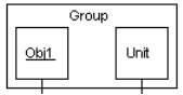
Groups related header elements into subsystems or components
Sequence Diagram Body Elements
Action
Represents an action taken by an actor, object or unit

Asynchronous Message
An asynchronous message between header elements

Block
A block representing a loop or conditional for a particular header element
Call Message
A call (procedure) message between header elements
CreateMessage
A “create” message that creates a header element (represented by lifeline going from dashed to solid pattern)
Diagram Link
Represents a portion of a diagram being treated as a functional block. Similar to a procedure or function call that abstracts functionality or details not shown at this level. Can optionally be linked to another diagram for elaboration.
Else Block Represents an “else” block portion of a diagram block

Message
A simple message between header elements
Return Message
A return message between header elements
Figure: 6.3.1
Sequence diagram for setting security codes.
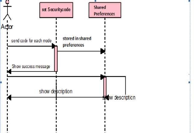
Description of sequence diagram: Actor sets a code for each mode and that code is saved
in the shared preferences.when actor sends that code for any other mobile ,mode of phone changes for given code.
Use Case Diagram
A use case diagram is a graph of actors set of use cases enclosed by a system boundary, communication associations between the actors and users and generalization among use cases. The use case model defines the outside(actors) and inside(use case) of the system’s behavior.
use case diagram is quite simple in nature and depicts two types of elements: one representing the business roles and the other representing the business processes.
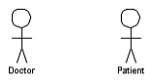
Figure 6.1: an actor in a use case diagram
To identify an actor, search in the problem statement for business terms that portray roles in the system. For example, in the statement “patients visit the doctor in the clinic for medical tests,” “doctor” and “patients” are the business roles and can be easily identified as actors in the system.
Use case: A use case in a use case diagram is a visual representation of a distinct business functionality in a system. The key term here is “distinct business functionality.” To choose a business process as a likely candidate for modeling as a use case, you need to ensure that the business process is discrete in nature.
As the first step in identifying use cases, you should list the discrete business functions in your problem statement. Each of these business functions can be classified as a potential use case. Remember that identifying use cases is a discovery rather than a creation. As business functionality becomes clearer, the underlying use cases become more easily evident. A use case is shown as an ellipse in a use case diagram (see Figure 3.2).
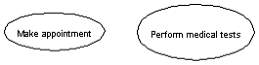
Figure 6.2: use cases in a use case diagram
Figure 6.2 shows two uses cases: “Make appointment” and “Perform medical tests” in the use case diagram of a clinic system. As another example, consider that a business process such as “manage patient records” can in turn have sub-processes like “manage patient’s personal information” and “manage patient’s medical information.” Discovering such implicit use cases is possible only with a thorough understanding of all the business processes of the system through discussions with potential users of the system and relevant domain knowledge.
Figure 6.3.2
USE CASE DIAGRAM
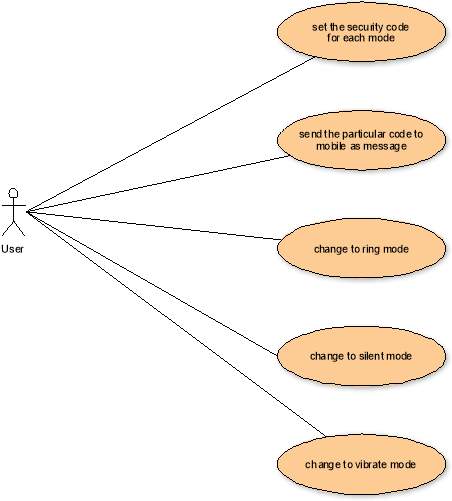
Description of Usecase diagram: user sets a code for each mode , and sends that particular code to mobile as a message.Then it changes to its respective modes.
Activity Diagram
Activity diagrams represent the business and operational workflows of a system. An Activity diagram is a dynamic diagram that shows the activity and the event that causes the object to be in the particular state.
So, what is the importance of an Activity diagram, as opposed to a State diagram? A State diagram shows the different states an object is in during the lifecycle of its existence in the system, and the transitions in the states of the objects. These transitions depict the activities causing these transitions, shown by arrows.
Figure 6.3.3 Activity Diagram
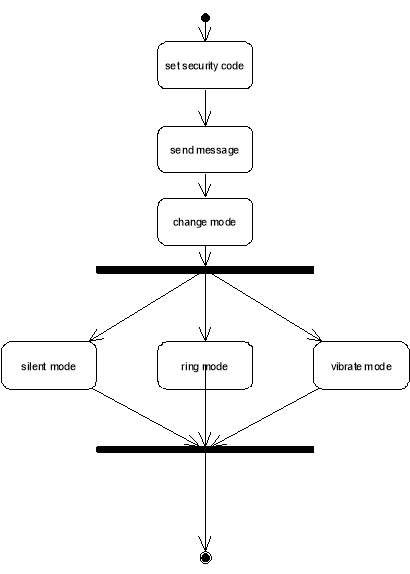
Description of Activity Diagram: Intially set a security code,then send a message ,then change mode to either silent or ring or vibrate mode .
Class Diagram
An object is any person, place, thing, concept, event, screen, or report applicable to your system. Objects both know things (they have attributes) and they do things (they have methods).
A class is a representation of an object and, in many ways, it is simply a template from which objects are created. Classes form the main building blocks of an object-oriented application. Although thousands of students attend the university, you would only model one class, called Student, which would represent the entire collection of students.
Responsibilities
Classes are typically modeled as rectangles with three sections: the top section for the name of the class, the middle section for the attributes of the class, and the bottom section for the methods of the class. Attributes are the information stored about an object, while methods are the things an object or class do. For example, students have student numbers, names, addresses, and phone numbers. Those are all examples of the attributes of a student. Students also enroll in courses, drop courses, and request transcripts. Those are all examples of the things a student does, which get implemented (coded) as methods. You should think of methods as the object-oriented equivalent of functions and procedures.
Figure 6.3.4:Class Diagram
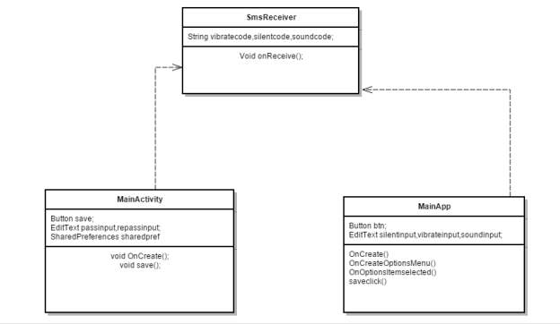
Class diagram description:MainActivity is java class handles the creating a password for opening app.
and for storing that app we use shared preferences and in Mainapp class we save the securecode for sound,silent and vibrate modes and those are also stored in shared preferences.Sms Receiver is class that runs in background and checks each message that comes to the phone.
State chart diagram
State chart diagram is used to describe the states of different objects in its life cycle. So the emphasis is given on the state changes upon some internal or external events. These states of objects are important to analyze and implement them accurately.State chart diagrams are very important for describing the states. States can be identified as the condition of objects when a particular event occurs.
Before drawing a State chart diagram we must have clarified the following points:
- Identify important objects to be analyzed.
- Identify the states.
- Identify the events.
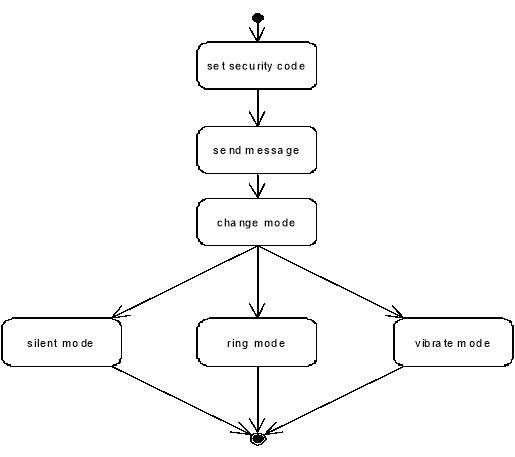
Figure 6.3.5:Statechart Diagram
7. SYSTEM TESTING
The purpose of testing is to discover errors. Testing is the process of trying to discover every conceivable fault or weakness in a work product. It provides a way to check the functionality of components, sub-assemblies, assemblies and/or a finished product It is the process of exercising software with the intent of ensuring that the Software system meets its requirements and user expectations and does not fail in an unacceptable manner. There are various types of test. Each test type addresses a specific testing requirement.
7.1 TYPES OF TESTS
1. Unit testing
Unit testing involves the design of test cases that validate that the internal program logic is functioning properly, and that program inputs produce valid outputs. All decision branches and internal code flow should be validated. It is the testing of individual software units of the application .it is done after the completion of an individual unit before integration. This is a structural testing, that relies on knowledge of its construction and is invasive. Unit tests perform basic tests at component level and test a specific business process, application, and/or system configuration. Unit tests ensure that each unique path of a business process performs accurately to the documented specifications and contains clearly defined inputs and expected results.
2. Integration testing
Integration tests are designed to test integrated software components to determine if they actually run as one program. Testing is event driven and is more concerned with the basic outcome of screens or fields. Integration tests demonstrate that although the components were individually satisfaction, as shown by successfully unit testing, the combination of components is correct and consistent. Integration testing is specifically aimed at exposing the problems that arise from the combination of components.
3. Functional test
Functional tests provide systematic demonstrations that functions tested are available as specified by the business and technical requirements, system documentation, and user manuals.
Functional testing is centered on the following items:
- Valid Input : identified classes of valid input must be accepted.
- Invalid Input : identified classes of invalid input must be rejected.
- Functions : identified functions must be exercised.
- Output : identified classes of application outputs must be exercised.
- Systems/Procedures: interfacing systems or procedures must be invoked.
Organization and preparation of functional tests is focused on requirements, key functions, or special test cases. In addition, systematic coverage pertaining to identify Business process flows; data fields, predefined processes, and successive processes must be considered for testing. Before functional testing is complete, additional tests are identified and the effective value of current tests is determined.
4. System Test
System testing ensures that the entire integrated software system meets requirements. It tests a configuration to ensure known and predictable results. An example of system testing is the configuration oriented system integration test. System testing is based on process descriptions and flows, emphasizing pre-driven process links and integration points.
5. White Box Testing
White Box Testing is a testing in which in which the software tester has knowledge of the inner workings, structure and language of the software, or at least its purpose. It is purpose. It is used to test areas that cannot be reached from a black box level.
6. Black Box Testing
Black Box Testing is testing the software without any knowledge of the inner workings, structure or language of the module being tested. Black box tests, as most other kinds of tests, must be written from a definitive source document, such as specification or requirements document, such as specification or requirements document. It is a testing in which the software under test is treated, as a black box .you cannot “see” into it. The test provides inputs and responds to outputs without considering how the software works.
7.2 Unit Testing:
Unit testing is usually conducted as part of a combined code and unit test phase of the software lifecycle, although it is not uncommon for coding and unit testing to be conducted as two distinct phases.
Test strategy and approach
Field testing will be performed manually and functional tests will be written in detail.
Test objectives
• All field entries must work properly.
• Pages must be activated from the identified link.
• The entry screen, messages and responses must not be delayed.
Features to be tested
• Verify that the entries are of the correct format
• No duplicate entries should be allowed
• All links should take the user to the correct page.
7.3 Integration Testing
Software integration testing is the incremental integration testing of two or more integrated software components on a single platform to produce failures caused by interface defects. The task of the integration test is to check that components or software applications, e.g. components in a software system or – one step up – software applications at the company level – interact without error.
Test Results: All the test cases mentioned above passed successfully. No defects encountered.
7.4Acceptance Testing
User Acceptance Testing is a critical phase of any project and requires significant participation by the end user. It also ensures that the system meets the functional requirements.
Test Results: All the test cases mentioned above passed successfully. No defects encountered
8. RESULTS & ANALYSIS
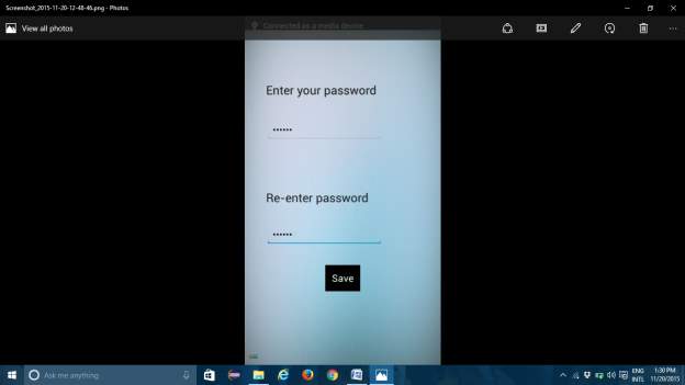
8.1 Start Up Screen
Set the password for the application
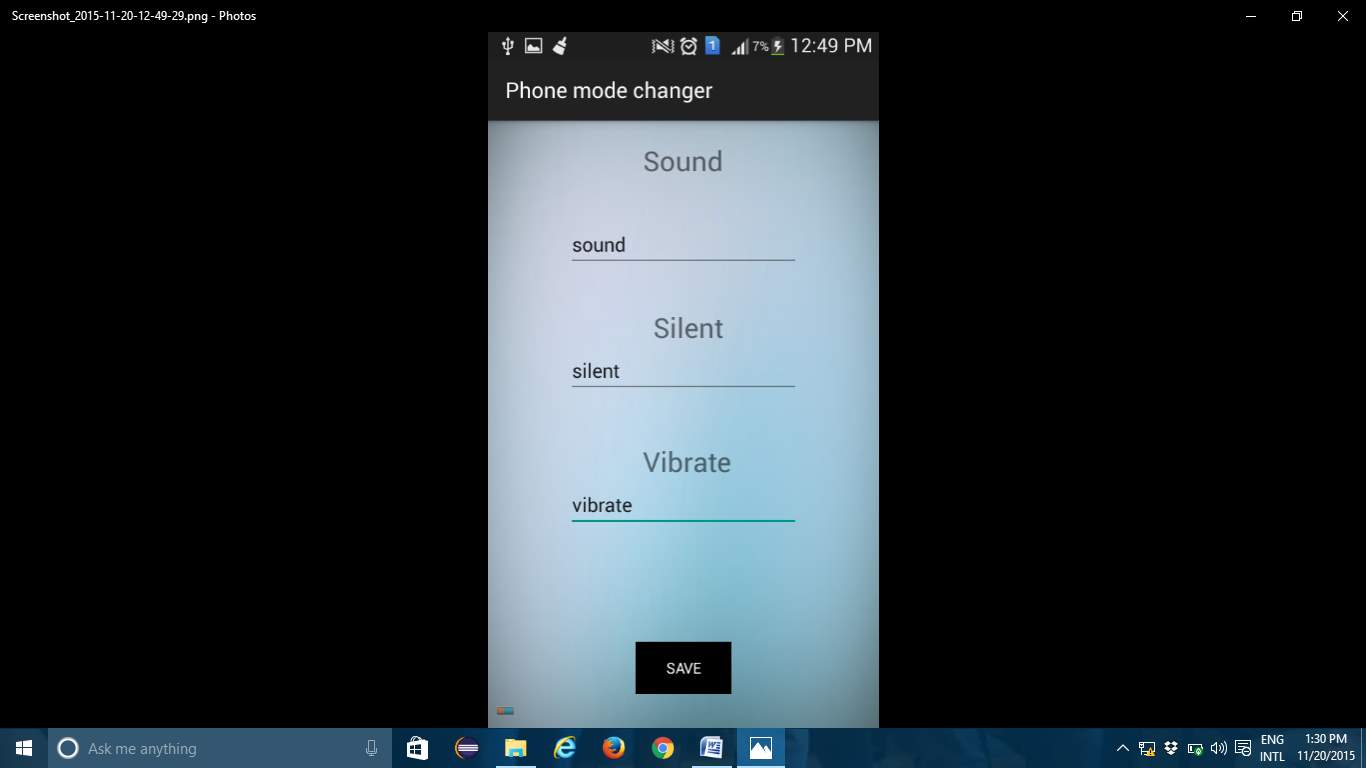
8.2 Main screen
Main Screen
–> Set the secure codes for each mode
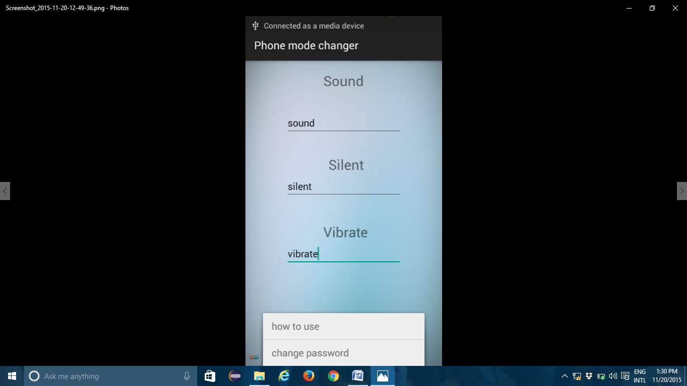
8.3 Options Menu
In the screen we will be having two options
1.how to use. 2.change password
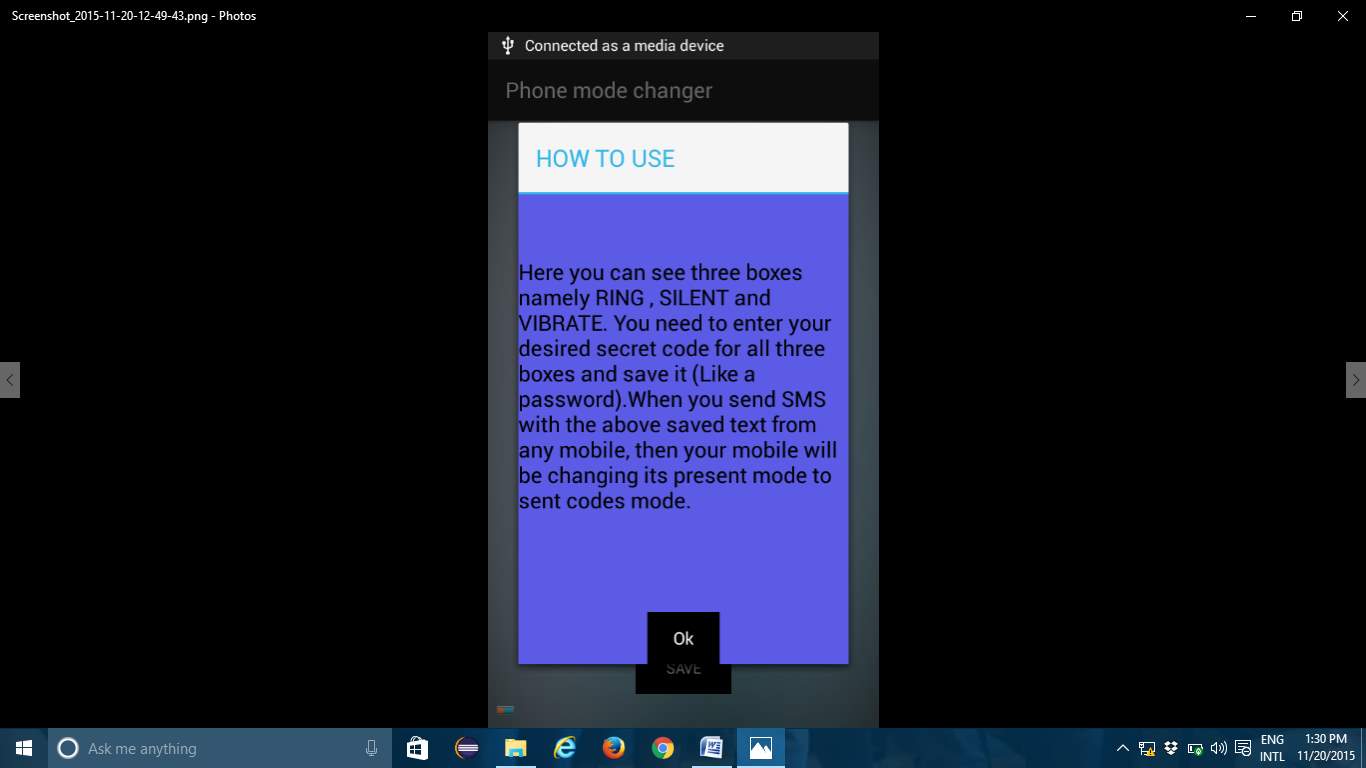
8,4 How to use
In this option naive users will know how to
use this application
8.5 Ring mode
Ring mode Silent mode
8.6 Silent Mode
Silent mode Vibrate mode
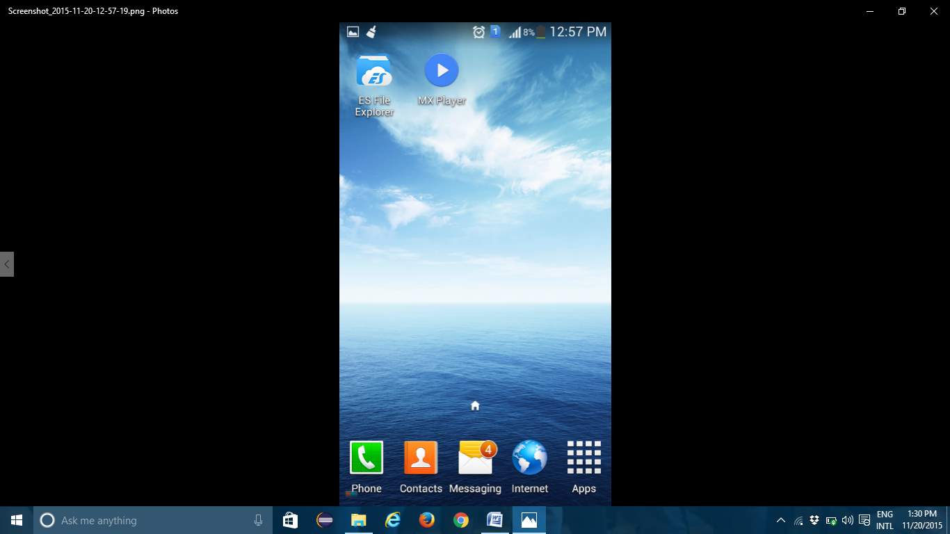
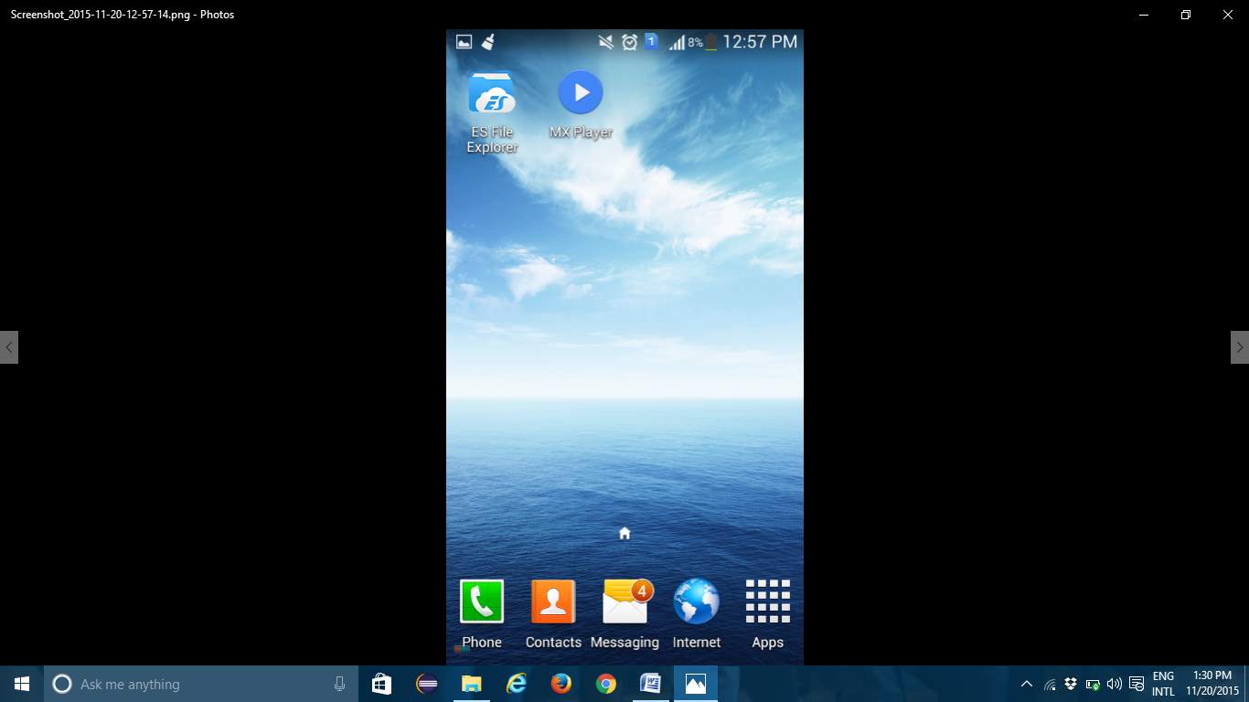
8.7 Phone Screen

8.8 Method of Implementation
Implementation literally means to put into effect or to carry out. The system implementation phase of the software deals with the translation of the design specifications into the source code. The ultimate goal of the implementation is to write the source code and the internal documentation so that it can be verified easily. The code and documentation should be written in a manner that eases debugging, testing and modification. System flowcharts, sample run on packages, sample output etc. Is part of the implementation?
An effort was made to satisfy the following goals in order specified.
• Minimization of Response Time.
• Clarity and Simplicity of the Code.
• Minimization of Hard-Coding.
Various types of bugs were discovered while debugging the modules. These ranged from logical errors to failure on account of various processing cases. Sequence diagram for setting security codes.
9. CONCLUSION
This application is used for changing phone mode. This application is build in Google mobiles using Android SDK. It is a tool developed for android platform, which is used to search various books and their related information within the mobile. This is an advantage when compared to existing system because a single mobile piece is enough for deploying the application .As this is a mobile application one can easily search for required information. One can search for books whenever one wants to without waiting for some system. This makes this application efficient, convenient and easy to use along with providing maximum user satisfaction which is the key aspect for any developer.
BIBLIOGRAPHY
- Herbert Schildt.2008 ,”Java Complete Reference”, Tata McGraw-Hill ,
7th Edition, pp.177-180 .
- Grady Booch, James Rambaugh.1998,“UnifiedModeling Language User Guide”, Addison Wesley Publishing, chapter 8-31.
WEBSITES: REFERRED URLS:
www.android.com http://developer.android.com/index.html
www.google.com http://en.wikipedia.org/wiki/SQL
Cite This Work
To export a reference to this article please select a referencing stye below:
Related Services
View all


Related Content
All TagsContent relating to: "Mobile Phones"
The first commercially available mobile phone was the Motorola DynaTAC 8000x, released in 1983. The high cost mainly restricted the first mobile phones to business until the early 1990’s when mass production brought cost effective consumer handsets. The launch of the first iPhone in 2007 introduced the world to the first phone that closely resembles what we know today.
Related Articles

DMCA / Removal Request
If you are the original writer of this dissertation and no longer wish to have your work published on the UKDiss.com website then please: