Development of Obstacle Avoiding Robot
Info: 11594 words (46 pages) Dissertation
Published: 22nd Dec 2021
CHAPTER #01: INTRODUCTION
1.1 Background
This report basically incorporates all the essential details of our final year project namely “OBSTACLE AVOIDING ROBOT” . We have tried our level best to explain each and every aspect of our final year project.
1.2 Purpose of Report
It’s the policy of the department to submit the final year project along with a detailed report. So, this report is compiled to fulfill this requirement. The purpose of this report can be summarized as:
- To explain every technical aspect of the project.
- To present the research done for this project in a compact way.
- To explore new areas of research.
- To provide convenience and adequate information to the ones willing to work on this project in future.
1.3 Robots and Robotics
An automation is a mechanical or virtual artificial agent, usually an electro-mechanical machine that is accompany by a computer program or electronic circuitry. Automation can be autonomous or semi-autonomous and range from mortal to industrial robots, collectively programmed swarm automation, and even microscopic Nano automation.
An automation is a machine driven device that sometimes relates to an individual and is capable of doing a variety of often complex human tasks on command or by being programmed in advance. The word Robotics is used to collectively define a field in engineering that covers the ape of various human characteristics.
The arm of technology that accord with the design, construction, operation, and application of automation, as well as computer systems for their control, sensory feedback, and information processing is automatic. These technologies accord with automated machines that can take the place of individual in dangerous surroundings or manufacturing processes, or relates humans in Robots are automatic machines that can take place of individuals in performing duty which individuals are unable to perform. Different automations are used for different projects.
1.4 Three Laws of Robotics
The Three principles of automations (often shortened to The Three Laws or Three Laws) are prescribed by the rules devised by the author Isaac. The fundamentals were introduced in his 1942 short story “Runaround”, although they had been foreshadowed in a few earlier stories. The Three principles are:
1. A robot may not injure an individual or, through inactivity, allow a human being to come to harm.
2. A robot must fallow the orders given to it by human beings, rather than where such orders would conflict with the First Law principle.
3. A robot must protect its own presence as long as such protection does not conflict with the First or Second Law principle.
1.5 INTRODUCTION
1.5.1 OBJECTIVE
The main objective of the project is to build a robot that is operable in two modes i.e. autonomous mode; in which robot will be capable of moving freely avoiding all obstacles in its path, while the other is manual mode user can control the robot from anywhere in the world via smart phone, connecting it to WiFi of his own workplace.
1.5.2 Autonomous mode
One operational mode of the robot is autonomous mode. In this mode robot is made to move in an obstacle free path i.e. without coinciding to the objects coming in its path. Obstacle avoidance is the basic of almost all robots.
Obstacles can be avoided either manually or using sensors. Following are the two sensors which are used for this purpose:
- Ultrasonic sensors
- Infrared sensors
1.5.3 Manual mode
The other operational mode of robot i.e. manual mode is designed so that the robot would be capable of communication. The project is built to provide full duplex communication link between robot and user. The system consists of the controlling device (i.e. smart phone), an intermediate data interpreter/server (a webserver) and a robot. Webserver is to act as a go between the robot and smart phone app. It interprets the orders sent by app, and provides a file by which the robot can read to resolve orders being sent to it.
CHAPTER #02: LITERATURE REVIEW
2.1 Mobile Robot
Mobile robot is an automatic machine that is able of locomotion. Mobile robots have the ability to move around in their surrounding and are not rigid to one physical area. Mobile robots can be “autonomous” (AMR – autonomous mobile robot) which means they are able of handle an uncontrolled situation without the need for physical or electro-mechanical guidance devices. As a matter of, mobile robots can rely on principles devices that allow them to travel a pre-defined cross route in relatively controlled space (AGV – autonomous guided vehicle). By contrast, industrial automations are usually more-or-less fixed, consisting of a jointed arm (multi-linked manipulator) and gripper assembly (or end effector), attached to a rigid surface.
2.1.1 Manual remote or tele-op
A standard tele-operated automation is totally under control of a driver with a joystick or other control device. The device may be put directly into the robot, may be without wire joystick, or may be an accessory to a wireless computer or other controller. A tele-op’d robot is commonly used to keep the operator out of harm’s way. Examples of standard remote robots include Robotics Design’s ANATROLLER ARI-100 and ARI-50, Foster-Miller’s Talon, iRobot’s PackBot, and KumoTek’s MK-705 Roosterbot.
2.1.2 Guarded tele-op
A guarded tele-op robot has the capability to sense and jump obstacles but will otherwise handle as driven, like a robot under standard tele-op. few if any mobile automations offer only guarded tele-op.
2.2 SOME EXAMPLES OF COMMUNICATION ROBOTS
Following are the some communicating robots which are used for surveillance and remote monitoring.
4WD WiFi Controlled Mobile Robot – IG32
This is Super Droid Robot’s Wi-Fi All Terrain Robot, Setup and fully massed. The robot is 4WD and is controlled from a PC over a Wi-Fi connection. Furnished with an IP camera mounted on a 360 degree pan and tilt system, it provides you with non-resembled vision.
The Wi-Fi controlled IG32 ATR includes the complete robot, Setup, gamepad controller so you can drive the robot right out of the box. Thanks to the on-board wireless bridge, the robot can be built to work from anywhere that has internet access with your Setup.
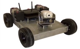
Fig 2.1: 4WD WiFi Controlled Mobile Robot – IG32
Surveyor SRV-1 WiFi webcam robot
Project for survey, education, and exploration, Surveyor’s SRV-1 internet-controlled robot blend a 1000MIPS 500MHz Analog Devices Blackfin BF537 processor, a digital video camera with resolution from 160×28 to 1280×1024 pixels, laser pointer ranging, and WLAN 802.11b/g networking on a quad-motor tracked mobile automatic base.
Working as a remotely-controlled webcam or a self-handling autonomous robot, the SRV-1 can run onboard understood C programs or user-modified firmware, or be remotely managed from a Windows, Mac OS/X or Linux base station with Python or Java-based console software. The Java-based console software includes a built-in web server to recognize and restrict the SRV-1 via a web browser from anywhere in the world, as well as archive video feeds on demand or on a scheduled basis. Additional software support for the SRV-1 is also available by way of RoboRealm machine vision software, Microsoft Robotics Studio, and Cyberbotic’s Webots.
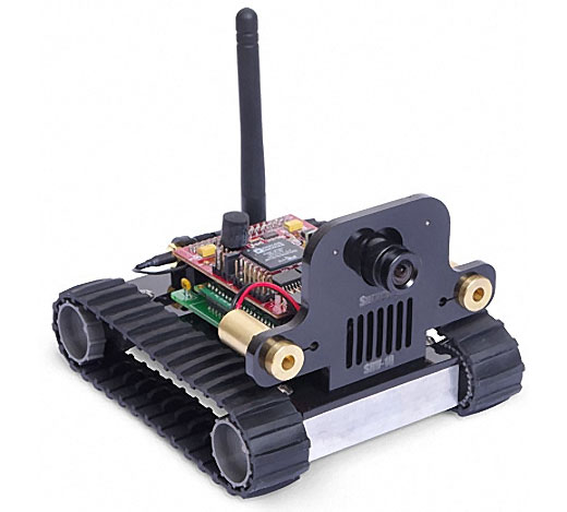
Fig 2.2: Surveyor SRV-1 WiFi webcam robot
ANATROLLER ARI-100
It is also an example of standard controlled automation. The ARI- 100™ of ANATROLLER™ is a specialized automation dedicated to duct cleaning and checking. It involve our articulated guidance that can move in all directions allowing it to clean all corners of the duct without ever having to standard adjustment of the length of the brush, ignoring a quality job behind it every time. It is structured with Robotics Design’s patented ANAT™ modular shape-shifting technology, and is less weight, durable, resilient, adaptable and easy to handle. It is Robotics structure’s most powerful robot for brushing, and with its capability to clean 150 feet/hour our users have reported a full return of investment within only six months of purchase. The ARI-100™`s ideal capabilities restrict it the most efficient robot for HVAC cleaning and checking on the world market. We also offer customized designs and add-ons for special principle and to better fulfill your individual requirements.
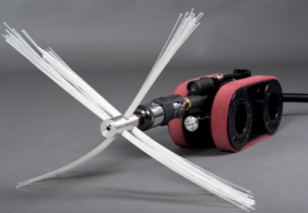
Fig 2.3: ANATROLLER ARI-100
WIFIBOT
The theme of WIFIBOT is to develop and make low cost robotic systems for an increasing number of applications using off the shelf technologies like the WiFi, which is the common denominator of all our products. WIFIBOT was born to fulfill the requirement there was in the market for affordable and technically intermediate mobile automation. The present option would either fall into the area of toys either into the category of expensive advanced robots intended for survey. The WIFIBOT products come in the middle of the two and face little competition in this category. The final goal of WIFIBOT is to take out robotics from the labs by proposing products presenting intermediate abilities and features while remaining functional and affordable to a large public.
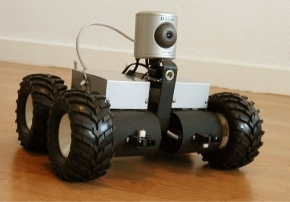
Fig 2.4: WIFIBOT
CHAPTER# 03: BASIC DESIGN
The robot has two operational modes;
- Autonomous mode
- Manual mode
Both the modes are achieved using the different software and hardware tools.
3.1 HARDWARE EQUIPMENTS
Following hardware equipments are used to build the robot.
- Arduino
- Ultrasonic sensor
- Arduino Wifi Shield
- Motor driver and motors e.t.c.
Arduino is used as the brain of the Robot, as it is responsible for the decisions and the actions to be performed by the robot. A Wifi Sheild is used to communicate between robot and user, since it connects the Arduino to the internet wirelessly, so that the robot can send and receive the data to and from the user via wifi. While the user can control the robot using the smart phone, either connecting it to 3G or wifi, for long range control with fast data rate capability.
Arduino
Arduino is a simple microcontroller board and open source development environment that allows to make devices that drive both functional and creative. It is a flexible and easy to use tool for sensing the environment by receiving input from a variety of sensors and can affect its surroundings by controlling outputs and actuators.
The board of arduino which is used in this project is Arduino UNO. The Arduino Uno is a micro handler board based on the ATmega328. It has 14 digital ip/op pins (of which 6 can be used as PWM outputs), 6 analog inputs, a 16 MHz ceramic resonator, a USB connection, a power jack, an ICSP header, and again set button. It includes everything require to support the micro handler; simply attach it to a computer with a USB cable or power it with a AC-to-DC adapter or battery to get started.
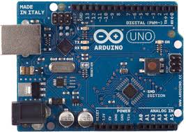
Fig 3.1: Arduino Uno R3
3.1.2 Ultra Sonic Sensor
Here HCSR04 ultrasonic sensor is used for obstacle detection. The HCSR04 ultrasonic sensor uses sonar to determine distance to an object like bats or dolphins do. It offers excellent noncontact range find with high accuracy and stable readings in an easy to use package. Its range is from 2cm to 400 cm or 1” to 13 feet. Its operation is not affected by sunlight or black material (although acoustically soft materials like cloth can be difficult to detect). It comes complete with ultrasonic transmitter and receiver module.
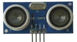
Fig 3.2: HSR04 Ultrasonic sensor
The timing diagram of HCSR04 is shown. To start measurement, Trig of SR04 must receive a pulse of high (5V) for at least 10us, this will initiate the sensor will transmit out 8 cycle of ultrasonic burst at 40kHz and wait for the reflected ultrasonic burst. When the sensor detected ultrasonic from receiver, it will set the Echo pin to high (5V) and delay for a period (width) which proportion to area. To obtain the area, measure the width (Ton) of Echo pin. Time = Width of Echo pulse, in uS (micro second)
- Area cover in centimeters = Time / 58
- Area cover in inches = Time / 148
- or using speed of sound, which is 340m/s
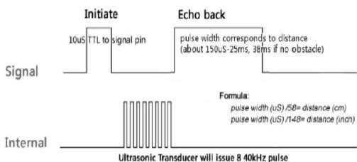
Fig 3.3: Timing diagram of HSR04
3.1.3 MOTORS AND WHEELS
The mechanical design of the robot is basically of a three wheel drive design; one at the front of the vehicle and other two at the back side. Front wheel is for left and right turns, while for power and speed control of the vehicle, back wheels are responsible. Two motors are used to run this vehicle; a DC motor for back wheels and a servo motor for front wheel.
3.1.3.1 DC motor
A DC motor is an electrical machine that converts direct current electrical power into mechanical power. It is mostly used to run vehicles because a DC motor’s speed can be controlled over a wide range, using either a variable supply voltage or by changing the strength of current. Hence a single DC motor is preferred to use to run both the wheels on back of the vehicle.
3.1.3.2 Servo motor
A servomotor is a rotary actuator that allows for precise control of angular position, velocity and acceleration. It consists of a suitable motor coupled to a sensor for position feedback. It is mostly used in the field of robotics to change the direction of the robot, or a part of robot. Hence it used in this project to control the direction of robot.
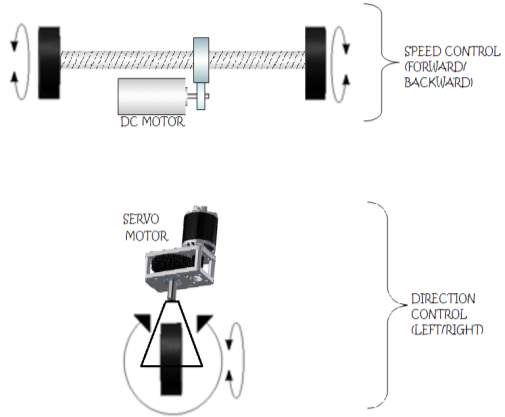
Fig 3.4: Motors and wheels configuration
3.1.4 Motor Driver
A motor driver IC i.e. L293D is used to drive the DC motor. This IC not only controls the direction of rotation but also the speed of the motor (continuous rotation in one direction). It is used to move and control the direction of back wheels. To move the robot forward or backward, the rotation of back wheels is needed to be changed. For this purpose H-Bridge configuration of L293D is used.The L293D is a very basic H-bridge. It has two bridges, one on the left side of the chip and one on the right, and can control 2 motors. It can drive up to 1 amp of current, and operate between 4.5V and 36V. The H-bridge has the following pins and features:
- Pin 1 (1,2EN) empower and disables our motor whether it is give HIGH or LOW
- Pin 2 (1A) is a logic pin for our motor (input is either HIGH or LOW)
- Pin 3 (1Y) is for one of the motor terminals
- Pin 4-5 are for ground
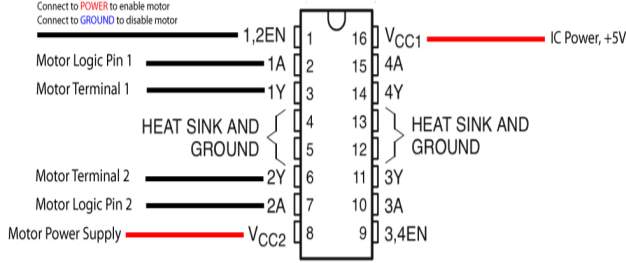
Fig 3.4: L293D Pins configuration
Followin table explains the direction of rotation of motor on the basis of its input at pins enable EN, input pins 1A and 2A. (Here L=low input, H=high input, X=doesn’t matter).
Table 3.1: L293D Functionality
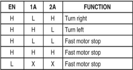
These input pins of L293D are connected to the output pins of Arduino, where it is programmed that what value is given to each input pin of L293D at a given time, so that the robot can decide its direction of movement.
3.1.5 Wi-Fi Arduino Shield
A wifi shield is also required to be placed inside the robot to connect it with local Wi-Fi network so that the data transfer between robot and user is made possible. For this purpose CC3000 Arduino Wi-Fi Shield is used that allows an Arduino board to connect to the internet using the 802.11 wireless specifications (Wi-Fi).
The CC3000 WiFi Module TI (Texas Instruments) is a self-contained wireless network processor that connect microprocessor to internet, incorporating internet connectivity into the project. Instead of the more standard UART communication method, the CC3000 module utilizes an SPI interface allowing the user to control the flow of data which makes the CC3000 uniquely able to associate to a WiFi access point using a cell phone app in the Texas Instruments process called SmartConfig.
The CC3000 Shield has a standard Arduino shield layout with 2 rows of pins on either side, while the CC3000 chip is on the back of the shield reducing the chance of interference from the barrel jack or USB connector.
Other Features:
- Supply Voltage: 4.5V – 12V
- Host Interface: SPI @ 16MHZ
- Throughput (TCP): ~4Mbps
- IEEE 802.11 b/g Compliant
- WEP, WPA/WPA2 (AES and TKIP – Personal) Security Modes
- FCC, IC, CE, and TELEC Certified
- Prototyping Area
- Onboard WIMAX Antenna
- Optional External Antenna Connection
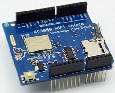
Fig 3.5: CC3000 WiFi Shield
3.2 SOFTWARE TOOLS
The softwares that are used to build the whole project are:
Wifi Bot Control
WiFi Bot Control is a WiFi based mobile phone application that allows the user to control the direction of the robot using the joystick in it. It connects to local wifi network and sends commands on to a local server, where data is further sent to the robot.
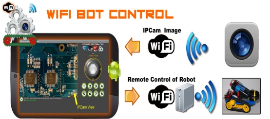
Fig 3.6: WiFi Bot Control App
3.2.2 Arduino IDE
Arduino is anopen-source electronic prototyping platform allowing creating interactive electronic objects. Arduino 1.0.3 is used in this project to program the arduino. Codes are written on this tool and directly uploaded via a USB cable. The environment is written in Java and based on Processing and other open-source software.
Reactor Server
Reactor Server is a software application designed specifically for making use of the Apache distribution using straightforward actions. It is designed to install the Apache distribution for Windows, more specifically MySQL, PHP, Perl, phpMyAdmin, PHP-Nuke and Zina.
This server is installed on a PC, once it is started; it behaves as a web server on a local network, and can be accessed from any device on that network. In the given figure, the files are shown, in the web browser, which are contained inside the server files.
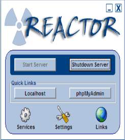
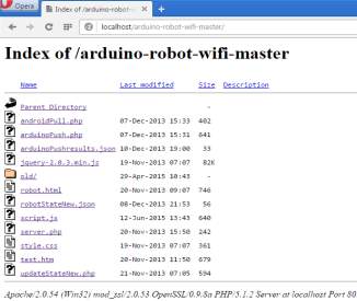
Fig 3.7: WebServer and its files
3.3 BLOCK DIAGRAM
Block Diagram of the whole system is given as:
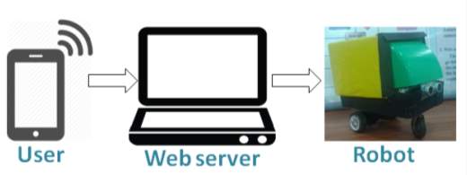
Fig 3.8: Block Diagram of the system
Following is the block diagram of the robot, which explans all the equipments and their connectivity inside the robot.
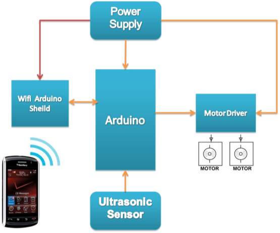
Fig 3.9: Block Diagram of the Robot
3.4 FLOW CHART
Flow chart of the system shows all the actions and decisions made by the controller in any embedded system. This flow chart explains the functionality of both the operational modes of the robot. In Autonomous mode, the robot continuously check if there is any obstacle, if yes, then it change its direction to either left or right. While manual mode, it checks according to the commands given by the user and follows the given direction.
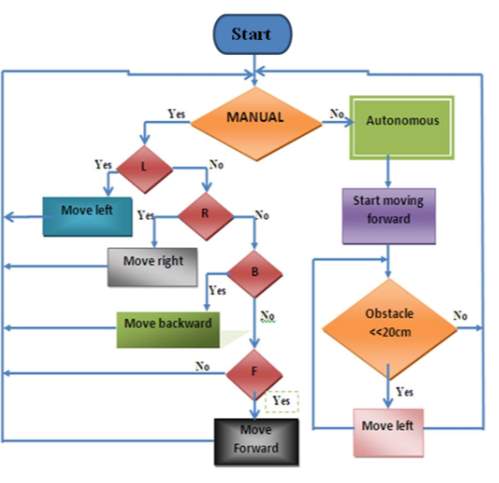
Fig 3.10: Flow Chart
Chapter# 04: AUTONOMOUS MODE
4.1 INTRODUCTION
Autonomous mode deals with the characteristic of obstacle avoidance of the robot. In this mode, robot is capable of avoiding obstacle and will make its own obstacle free path by using ultra sonic sensor. Ultrasonic sensor will generate sounds waves and detect obstacle and its distance from robot by time delay between generation of the sound waves and their reflection from obstacle. Servo motor is connected to front wheel of robot ,when sensor detect any obstacle it will inform aurdino and then aurdino will move motor accordingly and avoid obstacles.
4.2 OBSTACLE AVOIDANCE
In robotics, obstacle avoidance is the task of satisfying some control objective subject to non-intersection or non-collision position constraints. Normally obstacle avoidance is considered to be distinct that involves the pre-computation of an obstacle-free path which a controller will then guide a robot along. Obstacle avoidance is a means of a robot being able to move around in an unknown environment whilst not colliding with surrounding objects. Obstacle avoidance can be found on many different types of machines, big and industrial robots, or even on newer cars. Knowing how to program obstacle avoidance into robots can be a very useful skill to have, whether for a little robot project, or a larger project where obstacle avoidance is just a small piece of the large picture.
The efficient obstacle avoidance should be optimal with respect to:
- The overall goal
- The actual speed and kinematics of the robot
- The on board sensors
- The actual and future risk of collision
4.3 OBSTACLE AVOIDANCE MECHANISM
One operational mode of the robot is autonomous mode. In this mode robot is made to move in an obstacle free path i.e. without coinciding to the objects coming in its path. Obstacle avoidance is the basic of almost all robots.
Obstacles can be avoided either manually or using sensors. Following are the two sensors which are used for this purpose:
- Ultrasonic sensors
- Infrared sensors
In this project “ultrasonic sensor HSR04” is used for this purpose. It can detect objects from 2cm to 400 cm or 1” to 13 feet. This robot will detect object at distance of 30 cm we have set this distance.
4.3.1 Example
This example shows the whole mechanism of an obstacle avoiding robot. Ultra sonic sensor is used to check and detect for obstacles. If there is an object closer than 30 cm to our robot. The check has two possible outcomes, yes or no. Yes, meaning that there is indeed some object closer than 30 cm. No, meaning that there are no objects detected within 30 cm. If there is nothing within 30 cm the robot can simply move forward as the path is clear. If there is something closer than 30 cm the robot must perform obstacle avoidance maneuvers. The first stage of obstacle avoidance is to stop the robot! If you don’t stop the robot immediately it will crash. After the robot has stopped it needs to see what way it should go. It does this by looking both directions, much like you should when you cross the road. First the robot turns left, takes a reading, turns right, and takes a reading. Another check occurs to see what direction is the best way to go. If left is the way to go it has to turn back to the left and then go forward. If right is the way to go the robot simply moves forward as it is already facing in the right direction.
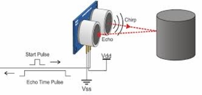
Fig 4.1: Ultrasonic mechanism
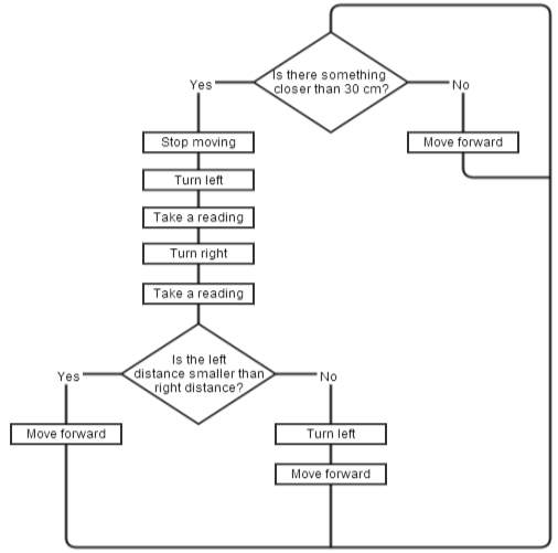
Fig 4.2: Obstacle Detection Flow Chart
This technique of obstacle avoidance makes the robot to:
- Detect obstacles
- Avoid obstacles
The technique that is adopted in the project is that when robot detects an object at 30cm or less, it moves backward, and checks again for the obstacle with the delay of 15 micro seconds. If the obstacle distance is again less than 30cm then it turns left, otherwise keep moving in forward direction.
CHAPTER# 05: MANUAL MODE
5.1 INTRODUCTION
The other operational mode of the robot is manual mode. In this mode, the robot can be controlled manually via Wi-Fi through smart phone App. The user can change the direction of robot as, and whenever he wants. This required the development of a full duplex communication link between both the devices, over which the data is continuously modified and transfer to each other. A web server is used as Communication Bridge between robot and app.
5.2 COMPONENTS
The manual mode system consists of three parts or components:
- the controlling device (i.e. smart phone)
- an intermediate data interpreter/server (a webserver)
- a robot.
Fig 5.1: Components of Manual mode
5.3 USER PART: WiFi Bot Control
On Client side there is a mobile application, named as WiFi Bot Control that inform the location of the robot.
WiFi Bot Control is an Android app that intends the client to remotely handle a device, presumably a robot. WiFi Bot Control is a project-specific app and is pretty much useless on its own. Client can also (optional) view a video stream from an IP camera mounted to the robot. WiFi Bot Control also give up to 8 additional customizable order buttons that allow the client to do additional project on the robot. These orders can be used to initiate other activities such as enabling/disabling sensors, moving other servos / arms / picking something up, turning a LED on/off etc.
Features:
- Uses WiFi only to handle the robot and view the IP Camera stream
- Configure camera URLs (up to 3)
- 3 Joystick Modes: Default, Simple Mode and Orientation Sensor
- Supports up to 8 additional commands via Command Buttons.
- Configure WiFi packet interval.
- Supports a number of micro controllers – requires WiFi module/capabilities.
- Sample Arduino sketch provided (below link).
- Screen automatically re-sizes for smaller phones.
- Works with most any microhandle that is WiFi capable
5.3.1 JOYSTICK MODES
Following are the Joystick modes of the WiFi Bot Control:
5.3.1.1 Default Joystick Mode:
When the joystick is moved, x and y coordinates are packaged into a figurable URL string and transmitted. The following is a sample URL where the x value is 22 and y value is 44. This information is parsed into a json file and then read from the Arduino robot.
5.3.1.2 Simple Joystick Mode:
In Simple mode, the joystick has 4 arrows representing Forward (U), Reverse (D), Left (L) and Right (R). When client taps the arrows, the respective character is packaged into the URLudlr value and the URL string is transmitted. Tapping the center or releasing a button sends an S value (stop). Tapping the Up arrow would look like this:
5.3.1.3 Command Mode:
The custom features can be added to the robot with additional order and customize the sample sketch provided. When a Command button is clicked, a value (1-8) is moved to the URLcmdVal variable. (i.e. Command Button #4 sends URLcmd=4) Also note the URLMode value passed is 3. Below is a sample URL string:
5.3.2 Working of App
The automation fixedly polls the server and parses the json data file for up to date orders instructions. When using the joystick or command buttons in WiFi Bot Control, the app will send a URL string through a web component to a user customizable URL defined in the app. A php file will up to date the json file with the updates motor / command instructions. The Arduino, via the WiFi module, calls on a php file to parse the json file and gives the values it requires. It then trained this data to command the robot.
5.4 WEB SERVER
The aim of the webserver is to pretend as a go between the robot and WiFi Bot Control. It understood the commands sent by WiFi Bot Control, and gives a file by which the robot can read to resolve commands being sent to it. This webserver can be part of the robot, or cannot be a part of server.
A web server is an information technology that manages requests via HTTP, the basic network protocol used to distribute information on the World Wide Web. The term can refer either to the entire computer system, an appliance, or specifically to the software that accepts and supervises the HTTP requests The primary function of a web server is to store, process and deliver web pages to clients. The communication between client and server takes place using the Hypertext Transfer Protocol (HTTP).
5.4.1 Creating web server
If the server is created in the robot, then the robot can be handling from a remote location. But in this purpose a local server is created that can be accessed on any device connected to the local network. For this project a server, named as Reactor Server is installed on a PC, once it is started; it behaves as a web server on a local network.
The files, which are need to be accessed by both the end devices to transfer data between each other, are placed inside the server files. As soon as the server is started, a new drive starts running on the PC. This drive has a “Core” folder which further contains a folder named as “htdocs”. The server files which need to be accessed are placed here in the server. The list of files is also shown in the following figure.
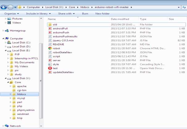
Fig 5.2: List of Server Files
The names and the functions of each server file are as follows, while their ccodes are written at the end of this report.
- updatestate.php:
This file is called from WiFi Bot Control to up to date robot state json with up to dated rates from the joystick / command buttons
- robotstate.json:
This file includes the actions for the robot. This file must be writeable by the IUSR web account of the webserver. Example contents: {“mode”:”1″,”xval”:”0″,”yval”:”0″,”udlr”:””,”cmdVal”:””}
- server.php:
This file is called from the Arduino robot and parses the json file (robotState.json for this)
- arduinoPush.php:
This file is called from the sketch and made the results in the json file. It also up to date the URL request in the sketch to match. The current sample is processed to write numeric values (i.e {“result1″:null,”result2″:3333}). To write text values, arduinoPush.php has to be modified to write value as text (i.e. {“result1″:”testA”,”result2″:”testB”})
- arduinoPushResults.json:
This file involves the sensor and other readings from the Arduino device. This file must be writable by the IUSR web account of the webserver. The file also read from WiFi Bot Control.
- androidPull.php:
WiFi Bot Control uses this file to parse and read the json file and use it to show sensor and other reading outfits.
5.4.2 Accessing the server files
To access the server files on the same PC, it is enough to put the name of the file to be opened in the web browser after writing “localhost/”. Here are the some files are shown opened in the browser in the following figure, along with the format of address writing.
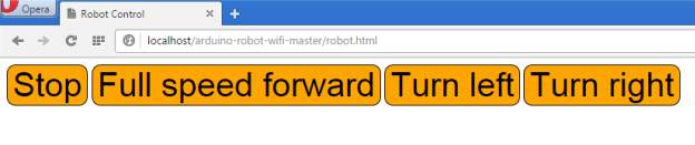
Fig 5.3: Robot.html opened in browser
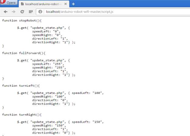
Fig 5.4: script.js opened in browser
But if the files are needed to be accessed by other devices, one should know the IP address of the PC that has web server installed on it. To check the IP, press start+R and open ‘cmd’ file. A black screen is opened. On writing ‘ipconfig’ command there, the IP address of the PC is shown.
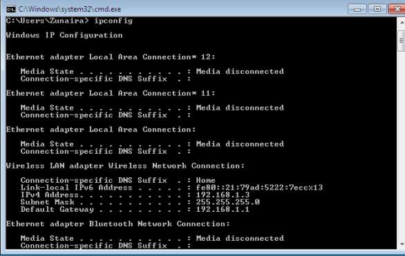
Fig 5.5: Checking IP address of Local Server
This IP address, along with the port number of the web server (usually 80), when entered in the other devices on local network, the files inside the server can be accessed. Thus this IP address is entered on both the end devices i.e. user side and the arduino side, to access the same files on the server at the same time.
Moreover, the file that updates the values and loads the json file is named as “updateStateNew.php”, so this file is called on both devices. The source code of this file, as well as all other server files is given at the end of this report.
The following figures show the address location in both the sides i.e. on android side as well as arduino side. Also it is shown that the same address (same file) is called on both sides.
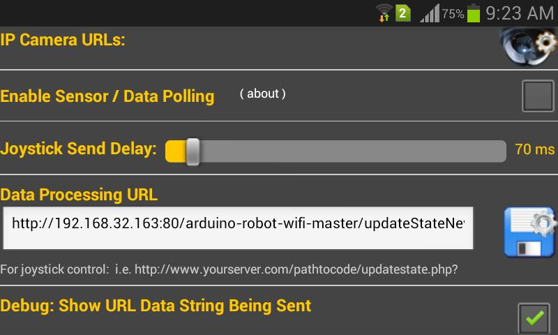
Fig 5.6: Address location on android side
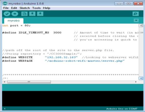
Fig 5.7: Address location on arduino side
CHAPTER# 06: RESULTS
Obstacle Avoidance Results
The robot is successfully made to move making an obstacle free path, which is without coinciding with the object coming in its path.
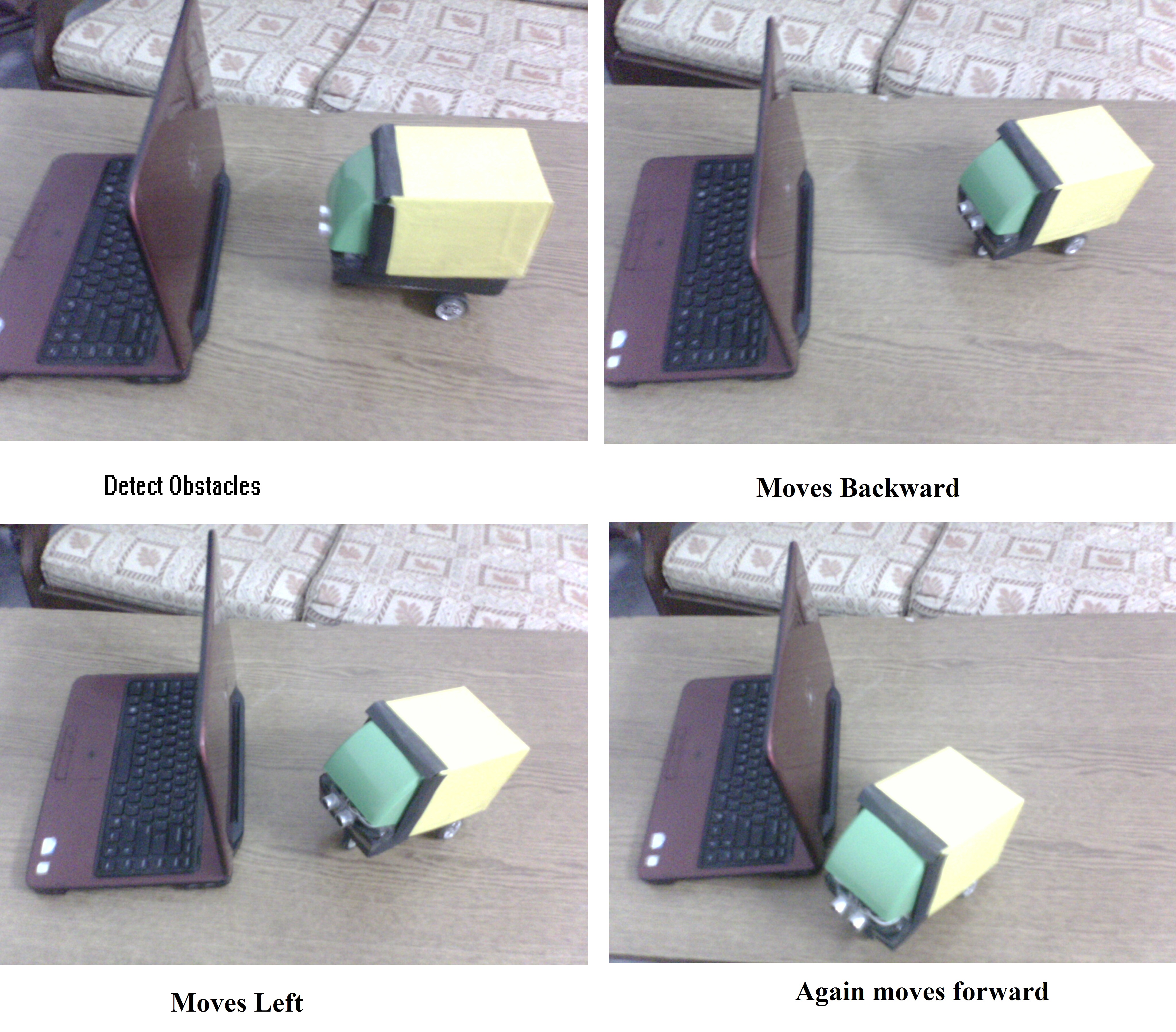
Fig 6.1: Robot Avoiding Obstacles
Connection of arduino to the local server
Following is the figure that shows the IP address of the arduino after connecting to the local network (using DHCP Configuration).
It also successfully connects to the web server and receives data from it.
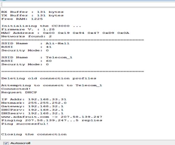
Fig 6.2: Local Server Connection to Arduino
Connection of app to local server
The connection between local server and WiFi Bot Control is also achieved successfully, and is capable of sending data i.e. command values to the websever which are further translated by the arduino.
Following are the two figures that show this connection. The first figure shows the error found in App when there is no address, or wrong address, is entered in URL that means no connection established between mobile and robot.
While in the second one, the connection is successfully achieved an App responds to the server.

Fig 6.3: Error before Connection
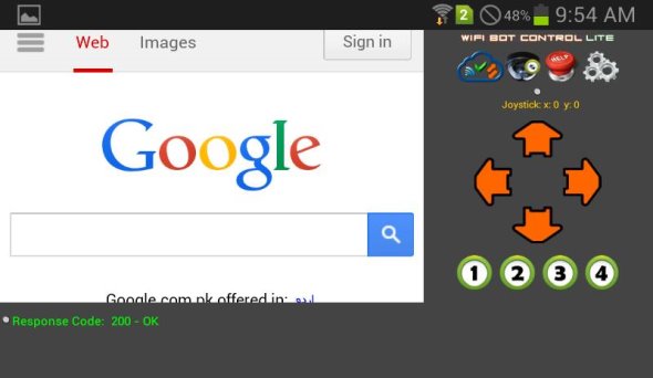
Fig 6.4: Response after Connection
CHAPTER#07: APPLICATIONS AND FUTURE RECOMMENDATIONS
7.1 APPLICATIONS
Obstacle ignoring method is very useful in real life, this method can also use as a vision belt of blind people by changing the IR sensor by a kinetic sensor ,which is on type of microwave sensor whose sensing range is very high and the outfits of this sensor vary in according to the object position changes. This method makes a blind people able to handle the obstacle easily by placing three vibrate in left, right and the centre of a belt named as VISION BELT and makes a blind people able to walk anywhere. One top of obstacle avoiding robot temperature/pressure sensors can be added to monitor the atmospheric conditions around. This is useful in places where the surrounding is not suitable for individuals.
Same technology can be used in various applications by modifying the micro handler program for example
- Line / Path finder Robot.
- As robotic vacuum cleaner.
- With proper setup we can use it as a weight lifter.
- In Mines
7.2 FUTURE RECOMMENDATIONS
The trend towards the design and need of robotic vehicles is growing continuously day by day. As the world is moving towards the automation and minimization of human interference, the importance of robots is increasing significantly.
Thus these are the some recommendations that are suggested to enhance the utilization and application of this project.
- Use a remote server instead a local web server, or put the sever inside the robot, so that it can be accessed from anywhere in the world. This will make the robot a long range communicating robot that the user can control the direction of the robot at remote distance, while connecting WiFi Bot Control to the network of his own work place.
- Add an IP camera over the robot to view a video stream, from the robot, on WIFI Bot Control. This not only adds wide range of applications to the project but also develops a full duplex communication link between the user and the robot.
- If both the above mentioned modification would be made in this project, The robot would be capable of:
- Surveillance in places where there is no space for humans to enter like at border for the tunnel surveillance.
- It can be used by snake catchers to get the insight of the snake holes.
- This robotic vehicle can also used in areas affected by radiations.
More modifications can also be made to this project as this robot is basic model of a project whose functionality can be doubled.
CONCLUSION
The project “Obstacle Avoiding Robot” along with the WiFi based communication link has been successfully designed, tested and operated in both the modes. Presence of every module has been reasoned out and placed carefully thus contributing to the best working of the unit.
From this survey, a moving robot that gets the stated objectives had been invented. This robot is able to produce the basic walking movements using two gear motors. we developed the robot with a very good intelligence which is easily able to sense the obstacle and by asuming the signal coming from the sensor it is perfectly avoiding the obstacle coming in between the path .Robot take the left or right or the forward movement in according to the sensing signal with the help of the two gear motor which makes the movement of the robot smooth .In future, the sensing range can be increased by increasing the sensor quality with the help of ultrasonic sensor or the IR signal stretch all over the provide area.
Our project has been successfully implemented encompassing all the mentioned features like Obstacle detection, webserver development and manual control.
Although this project is a complete package nevertheless, there is always a room for improvement. A lot of improvements can be made in its design and a lot of things can be added to make it a better unit.
Appendix
SOURCE CODES
Source Code of Autonomous mode
#include
const int motor01Pin = 7;
const int motor02Pin = 4;
const int enable Pin = 9;
int trig-jump Pin = 6;
int echo-jump Pin = 8;
long duration, cm, inches;
Servo my_servo;
int pos = 90
char dir;
void setup() {
Serial.begin (9600);
pinMode(trig-jump Pin, OUTPUT);
pinMode(echo-jump Pin, INPUT);
pinMode(motor01Pin, OUTPUT);
pinMode(motor02Pin, OUTPUT);
pinMode(enable Pin, OUTPUT);
myservo.attach(2);
pinMode(2, OUTPUT);
digitalWrite(enable Pin, HIGH);
}
void loop() {
digitalWrite(trig-jump Pin, LOW);
delayMicroseconds(5);
digitalWrite(trig-jump Pin, HIGH);
delayMicroseconds(10);
digitalWrite(trig-jump Pin, LOW);
digitalWrite(motor01Pin, HIGH);
digitalWrite(motor02Pin, LOW);
pinMode(echoPin, INPUT);
duration = pulseIn(echoPin, HIGH);
cm = duration/58;
inches = duration/148;
if (cm <= 30)
{
digitalWrite(motor01Pin, LOW);
digitalWrite(motor02Pin, HIGH); delay(10);
if (cm <= 30)
{
for(pos = 90; pos <= 150; pos += 1) {
myservo.write(pos);
delay(15); }
pos=90;
myservo.write(pos);
}
}
}
Source Code for manual mode
/*
Simple robot control with Arduino & the CC3000 WiFi chip
*/
#include
#include
#include
#include
#include “utility/debug.h”
#include
#include
String result;
int motorCommand[5];
{“mode”:”1″,”xval”:”0″,”yval”:”0″,”udlr”:””,”cmdVal”:””}
int resultLength;
const int enablePin = 9;
#define ADAFRUIT_CC3000_IRQ 3
#define ADAFRUIT_CC3000_VBAT 5
#define ADAFRUIT_CC3000_CS 10
const unsigned long
dhcpTimeout = 60L * 1000L,
connect Timeout = 15L * 1000L,
response Timeout = 15L * 1000L;
uint32_t t;
Servo myservo;
int pos = 90; char dir;
int counter = 0;
#define WLAN_SSID “Telecom_1”
#define WLAN_PASS “”
#define WLAN_SECURITY WLAN_SEC_WEP // This can be WLAN_SEC_UNSEC, WLAN_SEC_WEP, WLAN_SEC_WPA or WLAN_SEC_WPA2
// Create CC3000 instances
Adafruit_CC3000 cc3000 = Adafruit_CC3000(ADAFRUIT_CC3000_CS, ADAFRUIT_CC3000_IRQ, ADAFRUIT_CC3000_VBAT,
SPI_CLOCK_DIV2);
// Local server IP, port, and repository
//Looking to webserver
uint32_t ip = cc3000.IP2U32(192,168,32,163);
int port = 80;
// Amount of time to wait (in milliseconds) with no data
#define IDLE_TIMEOUT_MS 3000
#define WEBSITE “192.168.32.163
#define WEBPAGE “/arduino-robot-wifi-master/server.php”
void setup(void)
{
Serial.begin(115200);
result = “”;
pinMode(motor01Pin, OUTPUT);
pinMode(motor02Pin, OUTPUT);
pinMode(enable Pin, OUTPUT);
myservo.attach(2);
pinMode(2, OUTPUT);
digitalWrite(enable Pin, HIGH);
Serial.println(F(“Hello, CC3000! ”));
displayDriverMode();
Serial.print(“Free RAM: “); Serial.println(getFreeRam(), DEC);
/* Initialise the module */
Serial.println(F(“ Initialising the CC3000 …”));
if (!cc3000.begin())
{
Serial.println(F(“Unable to initialise the CC3000! Check your wiring?”));
while(1);
}
/* Update the Mac Address to a known value */
uint8_t macAddress[6] = { 0x08, 0x00, 0x28, 0x01, 0x79, 0xB7 };
if (!cc3000.setMacAddress(macAddress))
{
Serial.println(F(“Failed trying to update the MAC address”));
while(1);
}
uint16_t firmware = checkFirmwareVersion();
if (firmware < 0x113) {
Serial.println(F(“Wrong firmware version!”));
for(;;);
}
displayMACAddress();
/* Get the SSID list (not available in ‘tiny’ mode) */
#ifndef CC3000_TINY_DRIVER
listSSIDResults();
#endif
/* Delete any old connection data on the module */
Serial.println(F(“ Deleting old connection profiles”));
if (!cc3000.deleteProfiles()) {
Serial.println(F(“Failed!”));
while(1);
}
uint32_t ip Address = cc3000.IP2U32(192, 168, 1, 19);
uint32_t net Mask = cc3000.IP2U32(255, 255, 255, 0);
uint32_t default Gateway = cc3000.IP2U32(192, 168, 1, 1);
uint32_t dns = cc3000.IP2U32(8, 8, 4, 4);
if (!cc3000.setStaticIPAddress(ipAddress, netMask, defaultGateway, dns)) {
Serial.print ln(F(“Failed to set static IP!”));
while(1);
}
if (!cc3000.setDHCP()) {
Serial.println(F(“Failed to set DHCP!”));
while(1);
}
/* Attempt to connect to an access point */
char *ssid = WLAN_SSID; /* Max 32 chars */
Serial.print(F(“ Attempting to connect to “)); Serial.println(ssid);
if (!cc3000.connectToAP(WLAN_SSID, WLAN_PASS, WLAN_SECURITY)) {
Serial.println(F(“Failed!”));
while(1);
}
Serial.println(F(“Connected!”));
/* Wait for DHCP to complete */
Serial.println(F(“Request DHCP”));
while (!cc3000.checkDHCP())
{
delay(100); // ToDo: Insert a DHCP timeout!
}
/* Display the IP address DNS, Gateway, etc. */
while (! displayConnectionDetails()) {
delay(1000);
}
#ifndef CC3000_TINY_DRIVER
/* Try looking up localhost */
Serial.print(F(“webserver “));
while (ip == 0) {
if (! cc3000.getHostByName(“webserver”, &ip)) {
Serial.println(F(“Couldn’t resolve!”));
}
delay(500);
}
cc3000.printIPdotsRev(ip);
/* quick ping test on localserver */
Serial.print(F(“ Pinging “)); cc3000.printIPdotsRev(ip); Serial.print(“…”);
uint8_t replies = cc3000.ping(ip, 5);
Serial.print(replies); Serial.println(F(” replies”));
if (replies)
Serial.println(F(“Ping successful!”));
#endif
Serial.println(F(“ Closing the connection”));
cc3000.disconnect();
}
void loop()
{
String timeSec = String((int) counter);
String strDataToSend = “GET /arduino-robot-wifi-master/arduinoPush.php?URLresult1=11&URLresult2=” + timeSec + ” HTTP/1.1 Host:” + WEBSITE + “ ”;
//START Sending data to WiFi Bot Control example
Adafruit_CC3000_Client wwwSendData = cc3000.connectTCP(ip, port);
if (wwwSendData.connected()) {
wwwSendData.println(strDataToSend);
wwwSendData.fastrprint(F(“ ”));
wwwSendData.println();
}
else {
Serial.println(F(“Data Send”));
return;
}
wwwSendData.close();
while (wwwSendData.available()) {
wwwSendData.read();
}
//###################################################################
Adafruit_CC3000_Client www = cc3000.connectTCP(ip, port);
if (www.connected()) {
www.fastrprint(F(“GET “));
www.fastrprint(WEBPAGE);
www.fastrprint(F(” HTTP/1.1 ”));
www.fastrprint(F(“Host: “)); www.fastrprint(WEBSITE); www.fastrprint(F(“ ”));
www.fastrprint(F(“ ”));
www.println();
}
else {
Serial.println(F(“Data Receive”));
return;
}
/* Read data until either the connection is closed, or the idle timeout is reached. */
unsigned long lastRead = millis();
while (www.connected() && (millis() – lastRead < IDLE_TIMEOUT_MS)) {
while (www.connected()) {
while (www.available()) {
char c = www.read();
result = result + c;
// Delete HTTP headers
if(result.endsWith(“Content-Type: text/html”))
result.toLowerCase();
if(result.endsWith(“content-type: text/html”))
{
//if true, it will essentially clear out all the header content that came before
//the actual motor values x,x,x,x, later this is also trimmed as there are spaces around it
result=””;
}
}
}
www.close();
// Format result and extract the variables
format_result(motorCommand,result);
// Print received values
Serial.println(“Result: ” + String(result));
Serial.println(“Motor 1 speed: ” + String(motorCommand[0]) + ” and direction: ” + String(motorCommand[2]));
Serial.println(“Motor 2 speed: ” + String(motorCommand[1]) + ” and direction: ” + String(motorCommand[3]));
Serial.println(“Mode: ” + String(motorCommand[0]));
Serial.println(“Motor 1 speed/dir: ” + String(motorCommand[1]));
Serial.println(“Motor 2 speed/dir: ” + String(motorCommand[2]));
Serial.println(“UDLRVal: ” + String(motorCommand[3]));
Serial.println(“CommandVal: ” + String(motorCommand[4]));
// Send motor commands
switch (motorCommand[0]) {
case 1:
//driving via joystick x,y values
if (motorCommand[1] != 0 && motorCommand[2] != 0)
{
driveMotors(motorCommand[1],motorCommand[2]);
}
break;
case 2:
//move forward
digitalWrite(motor1Pin, HIGH);
digitalWrite(motor2Pin, LOW);
break;
case 3:
//move backward
digitalWrite(motor1Pin, LOW);
digitalWrite(motor2Pin, HIGH);
break;
default:
//robot state
digitalWrite(motor1Pin, LOW);
digitalWrite(motor2Pin, LOW);
break;
}
// Reset result variable
result = “”;
counter ++;
}
/*******************************************************************/
void displayDriverMode(void)
{
#ifdef CC3000_TINY_DRIVER
Serial.println(F(“CC3000 is configure in ‘Tiny’ mode”));
#else
Serial.print(F(“RX Buffer : “));
Serial.print(CC3000_RX_BUFFER_SIZE);
Serial.println(F(” bytes”));
Serial.print(F(“TX Buffer : “));
Serial.print(CC3000_TX_BUFFER_SIZE);
Serial.println(F(” bytes”));
#endif
}
/*******************************************************************/
uint16_t checkFirmwareVersion(void)
{
uint8_t major, minor;
uint16_t version;
#ifndef CC3000_TINY_DRIVER
if(!cc3000.getFirmwareVersion(&major, &minor))
{
Serial.println(F(“Unable to retrieve the firmware version! ”));
version = 0;
}
else
{
Serial.print(F(“Firmware V. : “));
Serial.print(major); Serial.print(F(“.”)); Serial.println(minor);
version = major; version <<= 8; version |= minor;
}
#endif
return version;
}
/*******************************************************************/
void displayMACAddress(void)
{
uint8_t macAddress[6];
if(!cc3000.getMacAddress(macAddress))
{
Serial.println(F(“Unable to retrieve MAC Address! ”));
}
else
{
Serial.print(F(“MAC Address : “));
cc3000.printHex((byte*)&macAddress, 6);
}
}
/*******************************************************************/
bool displayConnectionDetails(void)
{
uint32_t ipAddress, netmask, gateway, dhcpserv, dnsserv;
if(!cc3000.getIPAddress(&ipAddress, &netmask, &gateway, &dhcpserv, &dnsserv))
{
Serial.println(F(“Unable to retrieve the IP Address! ”));
return false;
}
else
{
Serial.print(F(“ IP Addr: “)); cc3000.printIPdotsRev(ipAddress);
Serial.print(F(“ Netmask: “)); cc3000.printIPdotsRev(netmask);
Serial.print(F(“ Gateway: “)); cc3000.printIPdotsRev(gateway);
Serial.print(F(“ DHCPsrv: “)); cc3000.printIPdotsRev(dhcpserv);
Serial.print(F(“ DNSserv: “)); cc3000.printIPdotsRev(dnsserv);
Serial.println();
return true;
}
}
/*******************************************************************/
void listSSIDResults(void)
{
uint32_t index;
uint8_t valid, rssi, sec;
char ssidname[33];
if (!cc3000.startSSIDscan(&index)) {
Serial.println(F(“SSID scan failed!”));
return;
}
Serial.print(F(“Networks found: “)); Serial.println(index);
Serial.println(F(“================================================”));
while (index) {
index–;
valid = cc3000.getNextSSID(&rssi, &sec, ssidname);
Serial.print(F(“SSID Name : “)); Serial.print(ssidname);
Serial.println();
Serial.print(F(“RSSI : “));
Serial.println(rssi);
Serial.print(F(“Security Mode: “));
Serial.println(sec);
Serial.println();
}
Serial.println(F(“================================================”));
cc3000.stopSSIDscan();
}
void format_result(int* array, String result) {
result.trim();
if (result.endsWith(“,”))
{
result = result.substring(0, result.length()-1);
}
result = result.substring(0, result.lastIndexOf(‘,’));
resultLength = result.length();
Serial.println(result);
Serial.print(” result length = “);
Serial.println(resultLength);
int commaPosition;
int i = 0;
do
{
commaPosition = result.indexOf(‘,’);
if(commaPosition != -1)
{
Serial.println( result.substring(0,commaPosition));
array[i] = result.substring(0,commaPosition).toInt();
Serial.print(“CommaPos: ” );
Serial.print (commaPosition);
Serial.print(” MotorVals: ” );
Serial.print(array[i]);
i = i+1;
result = result.substring(commaPosition+1, result.length());
Serial.print(” NextResult: ” );
Serial.println(result);
}
else
{
if(result.length() > 0) {
Serial.println(result);
}
}
}
while(commaPosition >=0);
}
/~~~~~~~~~~~~~~~~~~~~~~~~~~~~~~~~~~~~~~~~~~~~~~~~~~~~~~~~~~~~~~/
void driveMotors(int xVal, int yVal)
{
float xPct=1.0;
int xAdj, yAdj;
xAdj = map(abs(xVal), 0, 100, 100, 255);
yAdj = map(abs(yVal), 0, 100, 100, 255);
//approach –
// if Y is positive, both motors are set to move forward, else reverse.
//the value for X will determine the relative speed of each motor.
//first determine the direction
if (yVal >= 0)
{
// motors moving fwd
digitalWrite(motor1Pin, HIGH); // set leg 1 of the H-bridge high
digitalWrite(motor2Pin, LOW); // set leg 2 of the H-bridge low
}
else
{
//move reversed
digitalWrite(motor1Pin, LOW); // set leg 1 of the H-bridge low
digitalWrite(motor2Pin, HIGH); // set leg 2 of the H-bridge high
}
//determine left / right
if (xVal <= 0)
{
if (xVal < -70 && (yVal <= 40 || yVal >= -40)) //fast turn
{for(pos = 90; pos <= 180; pos += 1) // goes from 0 degrees to 180 degrees
{ // in steps of 1 degree
myservo.write(pos); // tell servo to go to position in variable ‘pos’
delay(15); // waits 15ms for the servo to reach the position
}
pos=90;
myservo.write(pos);
}
}
else
{
if (xVal > 70 && (yVal <= 40 || yVal >= -40)) //fast turn
{
for(pos = 90; pos>=0; pos-=1) // goes from 180 degrees to 0 degrees
{
myservo.write(pos); // tell servo to go to position in variable ‘pos’
delay(15); // waits 15ms for the servo to reach the position
}
pos=90;
myservo.write(pos);
}
}
Serial.print(“yAdj: “);
Serial.print(yAdj);
Serial.print(” xVal: “);
Serial.print(xVal);
Serial.print(” 100-lesvxal:”);
Serial.print(100 – abs(xVal));
Serial.print(” 100-lesvxal/100: “);
Serial.println((100 – abs(xVal))/100, DEC);
delay(50);
}
/~~~~~~~~~~~~~~~~~~~~~~~~~~~~~~~~~~~~~~~~~~~~~~~~~~~~~~~~~~~~~~/
//use to map values to float.
float mapf (float x, float in_min, float in_max, float out_min, float out_max)
{
return (x – in_min) * (out_max – out_min) / (in_max – in_min) + out_min;
}
/~~~~~~~~~~~~~~~~~~~~~~~~~~~~~~~~~~~~~~~~~~~~~~~~~~~~~~~~~~~~~~/
SOURCE CODES OF SERVER FILES
Server.php:
// Load JSON state
$string = file_get_contents(“robotStateNew.json”);
$json_a= json_decode($string,true);
// Send command to robot
foreach ($json_a as $key => $val){
echo $val;
echo “,”;
}
?>
RobotStateNew.json:
{“mode”:”1″,”xval”:”0″,”yval”:”0″,”udlr”:””,”cmdVal”:””}
updateState.php:
// Load JSON state
$string = file_get_contents(“robotStateNew.json”);
$json_a= json_decode($string,true);
//first part is the name of the value in the json text file that will be read by server.php when called from Arduino
//second part is the URL value that is parsed.
$json_a[‘mode’] = $_GET[“URLmode”];
$json_a[‘xval’] = $_GET[“URLxval”];
$json_a[‘yval’] = $_GET[“URLyval”];
$json_a[‘udlr’] = $_GET[“URLudlr”];
$json_a[‘cmdVal’] = $_GET[“URLcmdVal”];
$fp = fopen(‘robotStateNew.json’, ‘w’);
fwrite($fp, json_encode($json_a));
fclose($fp);
?>
Script:
function stopRobot(){
$.get( “update_state.php”, {
motor1Pin: “0”,
motor2Pin: “1”,
);
}
function fullForward(){
$.get( “update_state.php”, {
motor1Pin: “1”,
motor2Pin: “0”,
);
}
function turnLeft(){
$.get( “update_state.php”, {
for(pos = 90; pos <= 150; pos += 1) { myservo.write(pos);
delay(15);
} } );
}
function turnRight(){
$.get( “update_state.php”, {
for(pos = 90; pos>=0; pos-=1
{
myservo.write(pos);
delay(15);
} } );
}
androidPull.php:
//used by the Android device to request data from the json file.
// Load JSON state
$string = file_get_contents(“arduinoPushResults.json”);
$json_a= json_decode($string,true);
// get the data written to the json file and return it to the Web object so it can be parsed by the Android device.
foreach ($json_a as $key => $val){
echo $val;
echo “,”;
}
?>
arduinoPush.php:
// Arduino device will call to this URL and pass on data. This file write to arduinoPushResults.json – which is read by the Android device
// Load JSON state
$string = file_get_contents(“arduinoPushResults.json”);
$json_a= json_decode($string,true);
//first part is the name of the value in the json text file that will be read by server.php when called from Arduino
//second part is the URL value that is parsed.
$json_a[‘result1’] = $_GET[“URLresult1”];
$json_a[‘result2’] = $_GET[“URLresult2”];
$fp = fopen(‘arduinoPushResults.json’, ‘w’);
fwrite($fp, json_encode($json_a));
fclose($fp);
?>
arduinoPushresults:
{“result1″:”11″,”result2″:”5407”}
Style:
body {
font-family: Helvetica;
}
.commandButton {
background-color: orange;
border: 1px solid black;
font-size: 40px;
cursor: pointer;
border-radius: 10px;
}
@media screen and (max-device-width: 400px) {
.commandButton {
width: 100%;
height: 200px;
border: 2px solid black;
font-size: 80px;
margin-bottom: 50px;
text-align: center;
}
}
REFERENCES
http://arduino.cc/en/Guide/ArduinoWiFiShield
http://robotoid.com/howto/materials-for-robot-building-an-introduction.html
http://en.wikipedia.org/wiki/Mobile_robot
http://www.engineersgarage.com/electronic-circuits/obstacle-avoiding-robot
http://www.power7.net/arduinoethernet.html
http://forum.arduino.cc/index.php?topic=148853
http://www.plastibots.com/index.php/2013/11/26/wifi-bot-control-android-app-wifibot/
http://www.bajdi.com/obstacle-avoiding-robot-made-from-cheap-parts/
http://letsmakerobots.com/robot/project/obstacle-avoidance-robot-car-arduino
http://www.instructables.com/id/How-To-Make-an-Obstacle-Avoiding-Arduino-Robot/
https://itp.nyu.edu/physcomp/labs/motors-and-transistors/dc-motor-control-using-an-h-bridge/
http://www.sundh.com/blog/2012/02/make-wishield-work-in-latest-arduino-ide/
http://forum.arduino.cc/index.php?topic=239043.0
http://www.engineersgarage.com/contribution/robo-control-over-wifiyh
http://www.instructables.com/id/How-To-Make-an-Obstacle-Avoiding-Arduino-Robot/
http://www.slideshare.net/Rahuldey1991/obstacle-avoidance-robot
http://hackedgadgets.com/2007/03/07/wifibot-wifi-robot/
http://science.howstuffworks.com/robot.html
http://www.engineersgarage.com/contribution/android-phone-controlled-robot-using-arduino
HC-SR04Users_Manual
Abbreviations
TED:Telecommunication Engineering Department
FYP: Final Year Project
Wi-Fi: Wireless Fidelity
TCP:Transmission Control Protocol
UDP: User Datagram Protocol
WEP: Wireless Encryption Protocol
WPA: Wi-Fi protected access
AP: Access point
IP: Internet Protocol
DHCP: Dynamic Host Configuration Protocol
4WD: Four wheel drive
PC: Personal Computer
URL: Uniform Resource Locator
Cite This Work
To export a reference to this article please select a referencing stye below:
Related Services
View all


Related Content
All TagsContent relating to: "Electronics"
Electronics regards the science and technology involved in the development of electrical circuits and electronic devices and equipment that use them.
Related Articles

DMCA / Removal Request
If you are the original writer of this dissertation and no longer wish to have your work published on the UKDiss.com website then please: