Microsoft Surface Table: 3D Modelling and Touch Controls
Info: 7968 words (32 pages) Dissertation
Published: 10th Dec 2019
Tagged: Information TechnologyTechnology
Executive Summary
This project is about the use of a Samsung SUR40 Surface Table, running PixelSense, for the 3D augmented visual map of the University of Surrey’s Institute for Communication Systems. The project interactively displays the real-time information from various sensors located around the building. This report expands more on the Surface Table device, the implementation of better touch controls for navigation and the various problems encountered during the implementation. In explicit terms, the Surface Table is the device running the 3D modelling software of this project. Microsoft Visual Studio, XNA framework, and the Surface SDK were the software developer tools used in creating the model. These tools are also being used in the modification of the program, and in the implementation of new features.
During development of this project, the implementation of a fully functional touch framework was researched extensively, all the way from Microsoft developed frameworks, to third party solutions. Eventually, a solution was implemented. The program currently responds to touch controls, but is heavily limited due to the support provided for the touch system in the SUR40 surface table.
Table of Contents
2.3. Window Presentation Foundation
Microsoft XNA Framework and Microsoft Surface SDK
Table of Figures
Figure 1. A System Properties window, showing the details on the touch capability.
Figure 2. An image showing the initial edition of the source code, with buttons.
Figure 3. The error shown when the program is being opened on a Windows 10 PC.
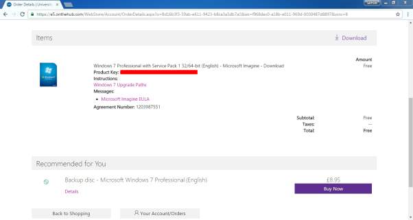
Figure 4. Image showing the free purchase of a Windows 7 Operating System, using Microsoft Imagine.
Figure 5. The image shows the procedure for creating a USB Key, Disk 2.
Figure 6. The image shows a properly installed XNA Game Studio Framework.
Figure 8. Image showing the concept behind circular motion, using cosine and sine functions.
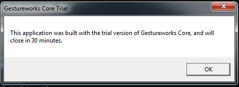
Figure 9. Image showing the trial prompt shown when running with the GestureWorks Core Trial
Figure 12. Image showing the app launcher through the Microsoft Surface Shell.
1. Introduction
1.1. Background and Context
Three-Dimensional (3D) Modelling is the process of creating a 3D representation of any surface or object by manipulating polygons, edges, and vertices, in simulated 3D space [1]. 3D modelling is used in many different industries, including virtual reality, video games, TV and motion pictures. A 3D modelling software generates a model through a variety of tools and approaches including [2]:
- Simple polygons.
- 3D primitives – simple polygon-based shapes, such as pyramids, cubes, spheres, cylinders, and cones
- Spline curves – a curve that connects two or more defined specific control points [3].
- NURBS (non-uniform rational b-spline) – Computationally complex, smooth shapes designed by bezel curves [3].
1.2. Scope and Objectives
In this project, the 3D model produced, was the 5G Innovation Centre at the University of Surrey. The final version of the prototype is supposed to be a model of the whole University campus, which would be able to display the temperature, noise levels, and a few other statistics in every single area on the map. To record data, an “IoT Desk Egg” [4] was created. This Desk Egg is a multi-sensor suite with feedback mechanisms and wireless communication capabilities. Using this Desk Egg, environmental data, such as light, sound, temperature, noise, humidity, dust density are measured and recorded. Separately, these recordings have limited value, but when combined, and analysed in aggregate, the sensors provide a rich context of its immediate surroundings.
The objective of this project is to enhance the model with touch navigation capabilities, like 3D navigation on a mobile phone or tablet. The current model is constructed for a Samsung SUR40 touch table, running Microsoft Surface. The model has been implemented using PixelSense and in addition, Microsoft Surface Game Studio 4.0 and the Window Presentation Foundation (WPF). To go about enhancing the model, investigations would have to be established, on what changes would be involved to implement touch navigation, before implementation and testing of the varieties.
In summary, the objectives to be achieved for this project are:
- To investigate what type of changes would be required to implement touch navigation.
- To implement suggested changes.
- To test the implementation of the new touch control system.
2. Technology review
2.1. Introduction
To develop a working touch functionality, a few frameworks and methods had to be researched. These include, the Microsoft PixelSense environment, the Window Presentation Foundation Framework, and the XNA Touch Input Framework.
2.2. Microsoft PixelSense
Microsoft PixelSense orientation capabilities are used and seamlessly integrated into the application, which also supports multiple simultaneous touch points [5]. The Samsung SUR40 can only run Windows 7, as the Surface SDKs are only fully supported on Windows 7 and not any newer Operating System.
2.3. Window Presentation Foundation
To initiate an application for any Microsoft Surface devices, especially for the PixelSense, the Microsoft Surface Game Studio 4.0 and Window Presentation Foundation (WPF) are required. Rowe (2012) shows a few points that can assist a developer to innovate and create a great application for the Samsung SUR40 Surface Table. [6]
- Implement a darker background as it does better with quality during contact.
- Multiple screen interactions, in which, the user’s finger and objects, can be detected.
- Actions only must be interacted by the user’s fingers to avoid detection errors, and adding sound effects, acknowledging the user’s finger interaction, should be done.
- Ensuring the user immerses into an outstanding experience from the application.
- Since the PixelSense has 4 corners, it will be more convenient for users to be able to turn the orientation of the application, while offering an easy means of leaving the application.
- The points of interaction with the application, should be well sized and well-spaced, to prevent manipulation errors during input.
2.4. Working with Touch Input
To implement the 3D touch controls, a key prerequisite for the project is the availability of touch control capability. Using the System Information app, which could be launched from the “Run” dialog box, with the syntax “msinfo32.exe”. As seen from the image below, the Samsung SUR40 Surface Table, has 52 individual touch points. This confirms that the table 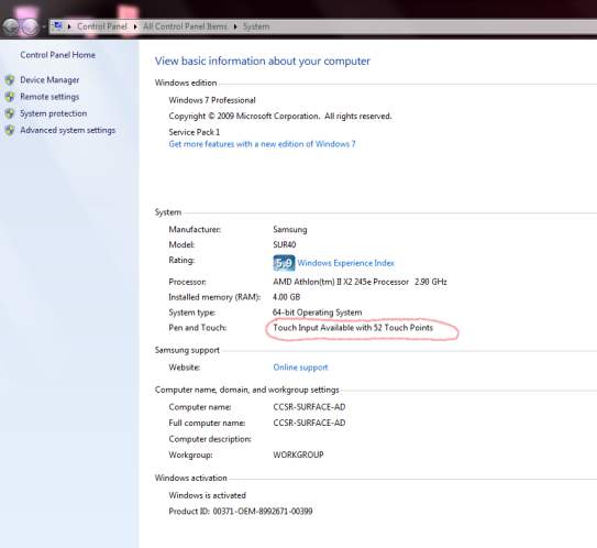 supports the touch interaction and the touch framework is ready to use.
3. Experimental Methods
The initial edition of the 3D modelling software has sub-par touch navigation controls, but it makes up in the availability of buttons which are mapped to specific viewing points of the model. Having these buttons provides a way of navigating through, but lack the fluidity of the touch input system you would get from any other 3D modelling software.
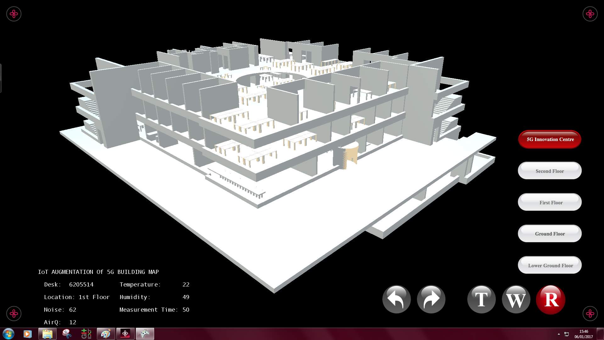
Figure 2. An image showing the initial edition of the source code, with buttons.
Developed by Tanapon Kraisirivet.
3.1. Development Environment
To be able to work on this project, a few software programs must be installed. These software programs are specifically required to create an application for a Microsoft PixelSense device.
These include:
- Windows 7
- Microsoft Visual Studio 2015
- Microsoft XNA Framework Redistributable 4.0 Refresh
- Microsoft XNA Game Studio Platform Tools
- Microsoft Surface 2.0 SDK
- Microsoft Surface 2.0 Runtime
- GitEXT
- The SUR40 Surface Table.
Windows 7
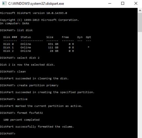
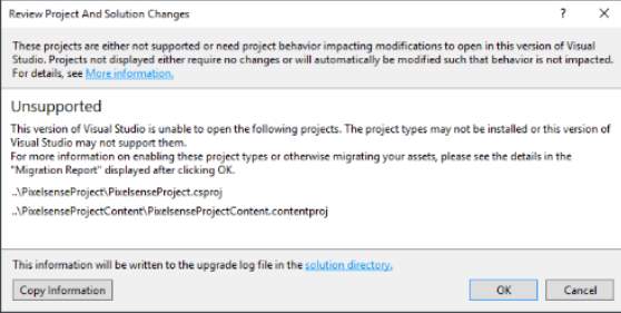 Windows 7 is the latest operating system that the Surface SDK supports, hence, all the programming done, had to be on a PC running Windows 7. Running these programs on a Windows 10 PC, gives an unfixable error. A Windows 7 license had to be purchased. Microsoft Imagine provides a free license to the University of Surrey students. Using the downloaded ISO file, a USB boot key was made, using “DiskPart”, to dual boot Windows 7 on the laptop used. Using DiskPart, empties the flash drive of all its contents, it’s advisable to use an empty drive, or back up its contents.
Figure 3. The error shown when the program is being opened on a Windows 10 PC.
DiskPart is the Windows built in disk management program, using CMD to call it, the following syntaxes will create a custom USB key for any appropriately sized flash drive:
- “List disk” – This lists out all the disk drives connected to the system, and their sizes, with disk numbers “Disk ###”, for easier disk reference.
- After finding your specific disk, use “select disk x”, x being the respective number of your disk. This basically tells the program you plan on working on this disk.
- “Clean” – This clears your drive of previous configurations and empties it.
- “Create partition primary” – This creates a primary partition on the cleaned drive.
- “Select partition 1” – This selects the recently created partition.
- “Active” – this sets the selected partition as an active partition.
- “Format fs=fat32” – This syntax formats the flash drive to a requested file system. In this example, the file system being “FAT32”, the legacy file system recognizable by most BIOS (Basic Input Output System) firmware.
Visual Studio 2015
Microsoft Visual Studio 2015 is now a free software, but for the Enterprise version, a key is needed, but as a University of Surrey student, one is provided free of charge, under the Microsoft Imagine account.
Microsoft XNA Framework and Microsoft Surface SDK
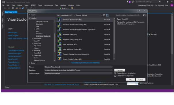 A Microsoft Surface SDK installer was downloaded and installed, as an extension, for the Visual Studio 15 suite. This enables Visual Studio to compile on the Microsoft Surface XNA Game Studio framework. The installer sets up two important frameworks, which are the Microsoft Surface WPF and Microsoft Surface XNA Game Studio 4.0. These frameworks are applied to help developers with the creation of two-dimensional (2D) and three-dimensional (3D) applications respectively. A successful install will show something like this, when creating a new project in Visual Studio.
GitEXT
GitEXT is an extension for windows, that helps manage a git repository. The program’s source code had to be worked on alongside a few colleagues, as they had other objectives in terms of updating the 3D Modelling software. Using a git repository, helps with management of different modifications and changes between different editors of the same source code.
SUR40
The Samsung SUR40 is a 2nd generation Microsoft Surface table top, is a 40-inch LCD computer, with the ability to process 52 individual multitouch points simultaneously.
The SUR40 does not have a normal touch screen digitizer, but its touch capabilities are provided through sensors behind the screen, that act like a camera. The technology is called PixelSense. For optimum performance of the PixelSense device, there are few rules that must be followed, in terms of location of the Surface Table. These rules were provided along with the table, in a document, called the Venue Readiness Guide. Some of these rules include [10]:
- Ensure that no light source is faced directly on or across the SUR40 screen.
The screen works like vision, light shining towards the screen, does not help it see better. Indirect lighting is strongly recommended.
- Ensure the SUR40 display does not have a light of sight with sunlight.
The sun is many thousand times brighter than indoor lighting. This therefore makes it difficult for the screen to read the display. To curb this however, please move the SUR40 away from any window, if the shades do not completely block sunlight.
- Use diffused energy efficient compact fluorescent lights (CFLs) or LEDs to light the surrounding area.
Usually, the lighting is not always constant, the best way to curb this problem, is to use the most accessible and stable source of indoor lighting, which are LEDs and CFLs
A much more extensive guide can be found in the manufacturer’s page, or the SUR40 User Manual.
4. Development
After researching various libraries and namespaces for a substantial understanding of the initial source code, coding began.
During initial coding, it was discovered that the method of navigating the model, was rotating the camera around a fixed object, as it gives the same illusion as the model moving around its axes, as opposed to the manipulation of the model itself in front of an immovable camera.
Using this logic, the touch code had to manipulate the camera’s movement and not the movement of the model.
While implementing the touch framework, a few redundancies were removed, such as the buttons used in moving the camera and a few others, to provide for a more immersive experience when using the 3D model.
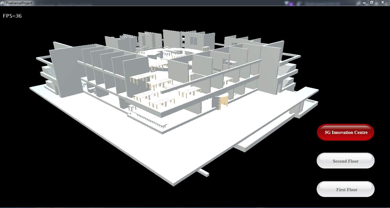
Figure 7. The image shows the 3D model with redundancies removed. Developed by Tanapon Kraisirivet, 2016.
4.1. Camera Movement
The Camera is not a hardware camera, more of an imaginary point in space that provides a point of view of the model to the user.
Running a camera location around an object is a concept of projecting different views from various positions for the user. It is an essential task for the developer to implement this concept in the application.
Camera Rotation
The current camera, as stated earlier, seen in Fig 3, has a fixed position, and does not move around the model, rather, there are fixed points, at which, the camera can be. These points are controlled by the arrow buttons.
The configuration for the camera had to be changed, so it has a smooth motion around the model. To implement, a series of translational calculations are required to move the camera from its current position to a desired place and display the object with high quality and performance. The movement of the camera is circular, hence it was logical to modify its straight-line movement with Cosine and Sine functions, so it had a more curved movement.
To change the rotational direction, the angle used in the formula is made negative. An illustration of the concept is shown below.
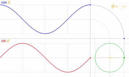
Figure 8. Image showing the concept behind circular motion, using cosine and sine functions.
Credit: google.com
When the camera rotates, the point of view is not fixed, so, during rotation, it would move around the model, but not always face the model. Usually, the “LookAt” function would be used to fix where the camera “looks at”. However, using this would create a lot of redundancies with how the camera was built in the original source code. Hence, using my new rotational function, as shown above, the yaw of the camera is made to rotate in the same direction and speed of the camera, that way it’s always fixed on the model.
Zoom in and Out
The basic idea of the zoom feature was to move the camera position from the current position to a closer point of view to the model, in the same direction. The direction of the camera movement is based on the x, y and z axes. This was implemented using the move function. The zoom resets, when a rotation event is called. This provides a better view of the rotation for the user.
4.2. Touch Gesture
The touch functionality of the program depended on raw input, and only moved the camera around a fixed point. The method of implementation made navigation with the touch screen, somewhat ineffective.
To fix this problem the touch framework must be implemented. A few methods approached for the implementation are listed below.
4.2.1. XNA Framework
Overview
The XNA framework installed, comes with a touch input namespace namely “Microsoft.Xna.Framework.Input.Touch”. After extensive research on this library namespace, using this namespace made implementing a new gesture-based, touch framework for the code straightforward.
The namespace provides support for gestures like tapping, double tapping, horizontal drag, and a few others. Here is a more extensive list of the gestures to be implemented, with their individual descriptions [7]:
| Member name | Description |
| Tap | The user briefly touched a single point on the screen. |
| DoubleTap | The user tapped the screen twice in quick succession. This always is preceded by a Tap gesture.
If the time between taps is too great to be considered a DoubleTap, two Tap gestures will be generated instead. |
| HorizontalDrag | The user touched the screen, and then performed a horizontal (left to right or right to left) gesture. |
| VerticalDrag | The user touched the screen, and then performed a vertical (top to bottom or bottom to top) gesture. |
| FreeDrag | The user touched the screen, and then performed a free-form drag gesture. |
| Pinch | The user touched two points on the screen, and then converged or diverged them. Pinch behaves like a two-finger drag. When this gesture is enabled, it takes precedence over drag gestures while two fingers are down. |
| Flick | The user performed a touch combined with a quick swipe of the screen. Flicks have no position. The velocity of the flick can be retrieved by reading the Delta member of GestureSample. |
| DragComplete | A drag gesture (VerticalDrag, HorizontalDrag, or FreeDrag) was completed. This signals only completion. No position or delta data is valid for this sample. |
| PinchComplete | A pinch operation was completed. This signals only completion. No position or delta data is valid for this sample. |
Implementation
The following steps were taken to fully include the XNA touch framework in the program.
- In the first few line of the code, a using function must be used, to reference the library in the project. This was done in both the Camera.cs class and the App1.cs code.
using Microsoft.Xna.Framework.Input.Touch;
- In App1.cs, to initialise the framework, a code should be written, telling the framework, what gestures to be expecting, so it streamlines its initialisation process, by not loading all gesture functions.
TouchPanel.EnabledGestures =
GestureType.Tap |
GestureType.FreeDrag |
GestureType.Pinch |
GestureType.Flick;
- After the definition process, the next block of code written is a barebones version of the one used in the code;
while (TouchPanel.IsGestureAvailable)
{
GestureSample gs = TouchPanel.ReadGesture();
switch (gs.GestureType)
{
case GestureType.Tap:
//insert function here
break;
case GestureType.FreeDrag:
//insert function here
break;
case GestureType.Pinch:
//insert function here
break;
case GestureType.Flick:
//insert function here
break;
}
The insert function here lines, are where the code will be linked to the camera movements, respective to the gesture.
Problems Faced
During the test phase, the program showed a promising functionality, when a debug write line was inserted, but as work continued, the surface table was required to be connected to the internet. As the table had a stable internet connection, it scheduled an automatic update. In this update, one of the changes was an update from windows which “cuts touch from Windows entirely” [8].
Running into a problem like this meant, all the work using this framework had to be undone, and a new method needed to be implemented.
4.2.2. GestureWorks Core
Overview
Per the GestureWorks website, “GestureWorks Core is a powerful authoring framework and touch point cluster analysis system for multitouch.” The GestureWorks Core multitouch framework, developed by Ideum™, works with different languages and other frameworks. Ideum is a company that specialises in the development of innovative hardware and software focused on Human-Computer Interaction (HCI). Ideum makes SDK’s for tables like the SUR40 and similar ones created by them also [9].
The GestureWorks Core uses an XML based gesture oriented user interface language, called the Gesture Markup Language (GML). The way this works is, the GML file, has the definitions of all the gestures needed for the application’s interaction. Here is a list of gestures defined by the basic manipulation GML file, included with GestureWorks:
| Gesture ID | Description |
| n-drag | The n-drag gesture is a drag gesture, can be activated by any number of touch points. When a touch down is recognized, the position of the touch point is tracked, and mapped directly to the position of the touch object. |
| n-rotate | The n-rotate is a multitouch based gesture, so at least 2 points are needed. When these touches are recognized, it maps the speed of rotation (delta) to the rotational speed of the model. |
| n-scale | This is also a multitouch based gesture, designed to provide object scaling or zoom, using any number of touch points. |
| n-tap | The n-tap gesture basically detects a short interaction from a touch point, and passes the location of the point to the application |
| n-hold | The n-hold function, detects a long press of a touch point, and passes the location of the touch point to the application for further processing. |
However, the GestureWorks Core multitouch framework is a paid service, but a trial version can be obtained from the Ideum website. The trial limits the usage of the framework to 30 minutes of a code run; a dialog box shows this as the code is being executed.
Implementation
Using this framework needed a bit of tweaking. The steps taken and their respective explanation can be seen below:
- Firstly, the Gestureworks Core framework is provided as an executable, installing it however, only extracts the useful files needed to be included in the Visual Studio (preferably the solution directory, that way, the git client can update other users) .
- The next step is to include the files needed for the framework association in the references list, to prevent errors when using GestureWorks definitions and classes.
- In the code solution, add a “using GestureWorksCoreNET” to reference the library within the project.
- To initialise GestureWorks, a few lines of code must be written;
- In the class definition, right below the “GraphicsDevice” and “Sb” lines, add a member field initialising a new GestureWorks object.
GestureWorks gw = new GestureWorks();
- For the final part of the initialisation, a few more lines of code must be added.
gw.LoadGestureWorksDll(“C:\Program Files (x86)\Ideum\GestureworksCore32.dll”);
gw.InitializeGestureWorks(1920, 1080);
gw.LoadGML(“C: C:\Program Files (x86)\Ideum\GestureworksCore32\basic_manipulation.gml”);
gw.RegisterWindowForTouch(this.Window.Handle);
- LoadGestureWorksDll() specifies the location of the GestureWorks library, the right dll file should be chosen, for the specific platform of the application i.e. 32 bit.
- InitializeGestureWorks() tells the core framework, what resolution the code is going to be running, in width and height, respectively.
- LoadGML() tells the core framework what GML file it is going to be referencing from.
- RegisterWindowForTouch() tells which window the core is detecting the gesture events from.
- After initialising GestureWorks, the inbuilt XNA Graphics device must be configured also. This was configured using the following steps and an explanation of their respective purpose.
- Right below the class definition in Step D. a.; insert this line of code, which adds a member field for the texture.
Texture2D _texture; // ← add this line
- In the App1 Constructor, the display should be configured further, with the screen’s dimensions, and a code to be able to toggle the full screen option, this however is disabled for debug reasons.
graphics.PreferredBackBufferWidth = 1920;
graphics.PreferredBackBufferHeight = 1080;
//graphics.ToggleFullScreen();
- The last step to the full configuration is being done in the update() loop. For the GestureWorks engine to keep updating and processing new changes, the process frame code must be toggled by using this line of code.
_gestureWorks.ProcessFrame();
- Before the framework begins to process the touch points, or any gesture events, the flowing code, is used to enable it to react to the touch interaction;
- In the App1 class, a new list of the active points is instantiated, as illustrated below;
List<PointEvent> _activePoints = new List<PointEvent>();
- Under the process frame function in step E. c., this block of code was written.
foreach (PointEvent point in _gestureWorks.ConsumePointEvents())
{
PointEvent existingPoint = _activePoints.Find(pt => pt.PointId == point.PointId);
switch (point.Status)
{
case TouchStatus.TOUCHUPDATE:
if(existingPoint != null)
existingPoint.Position = point.Position;
break;
case TouchStatus.TOUCHADDED:
_activePoints.Add(point);
break;
case TouchStatus.TOUCHREMOVED:
if (existingPoint != null)
_activePoints.Remove(existingPoint);
break;
default:
break;
}
}
This code, basically adds a new touch point, for each finger detected on the screen at a point in time.
- After following these steps the touch framework should be fully functional. To show that the screen framework is now processing the touchpoints.
- An additional step was added to the code, to help with easier debugging and performance review of Surface table. The code added, was also in the update loop. The function of this code was to track the activated touch points, and show a pointer in form of a ring, showing the position of the finger both visually and in terms of coordinates. To implement these, these lines of code were written;
- To display the visual acknowledgement of a touch point, the following code was used to implement the feature.
sb.Begin(SpriteSortMode.BackToFront, BlendState.AlphaBlend);
foreach (PointEvent point in _activePoints)
{
sb.Draw(
_texture,
new Vector2(point.Position.X, point.Position.Y),
null, //source rectangle
Color.White,
0, //rotation
new Vector2(_texture.Width / 2, _texture.Height / 2),
1.0f,
SpriteEffects.None,
0f);
}
sb.End();
- Right in the draw loop, in the step above, more development is needed to implement the point location of each finger, in terms of coordinates.
string positionString = String.Format(“ID: {0} X: {1} Y: {2}”, point.PointId.ToString(), ((int)point.Position.X).ToString(), ((int)point.Position.Y).ToString());
Vector2 positionStringCenter = _spr_font.MeasureString(positionString) / 2;
sb.DrawString(
_spr_font,
positionString,
new Vector2(point.Position.X + 80, point.Position.Y – 40),
Color.FromNonPremultiplied(96, 153, 6, 255),
0,
positionStringCenter,
0.75f,
SpriteEffects.None,
0.5f);
The code above, draws the TextID above the touch point, and the position to the right of each touch point.
After following these steps, the framework is finally initialised and ready to receive any gesture event or touch event.
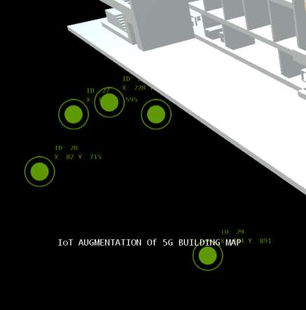
Figure 10. Image showing the 5 touch points being processed, and their respective information printed along.
Problems Faced
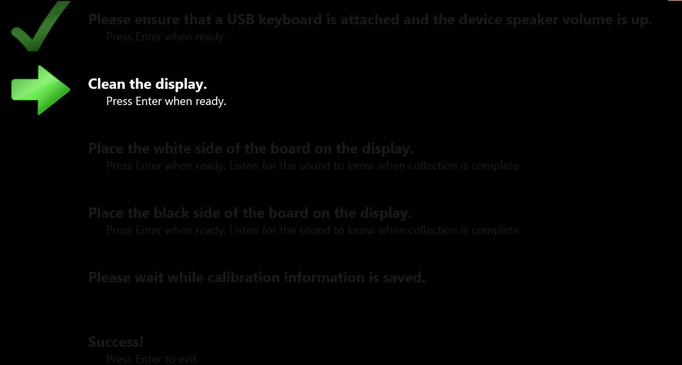
The initialisation stages of the GestureWorks core, worked perfectly and seamlessly as shown in the image above. However, when it came to the gesture recognition, the core was not able to match an input gesture to a pre-programmed gesture, as the precision of the panel was very weak, this issue could be due to the lack of calibration of the touch panel. The Surface Table could not be re-calibrated, as the calibration board is needed, but it could not be provided per request. Another cause of this problem could be due to the lighting conditions of the table’s surroundings, as it breaks a few rules, set by the manufacturer, in the Venue Readiness Guide [10].
 In tandem with the touch panel problems, the GestureWorks core support for XNA has now been deprecated, hence no further development with fixes or workarounds for the touch input, will be available.
Figure 11. Image showing the calibration process of the SUR40, asking for the calibration board in the third and fourth steps.
4.2.3. Direct Input
Overview
After the failure of the GestureWorks engine, the only method available was using the raw input of the Surface table. The only hindrance is, the raw input has no support for multitouch, as it converts the touch events into the mouse events.
Implementation
Due to the conversion of the touch events into mouse events, the implementation of this method was straight forward, as shown below;
MouseState statel= Mouse.GetState();
var mouseState = Mouse.GetState();
var mouseposition = new Point(mouseState.X, mouseState.Y);
if (mouseState.LeftButton == ButtonState.Pressed)//code for 1 finger
{
if (mouseposition.Y <= 768)
{
if (mouseposition.X <= 1366 / 2)//
{
Rotate1(false, 0.005f);
}
else
{
Rotate1(true, 0.005f);
}
}
}
As the mouse events, could not be mapped to the movement of the model, a function was created to handle the seamless movement of the model, so it can be called during the occurrence of a mouse event. The rotate function is shown below
public void Rotate1(bool direction, float angle)
{
if (direction)
{
yaw = Math.Abs(angle); //camera – right
cameraPosition.X = centreX + (float)Math.Sin(-angle) * 20f;
cameraPosition.Z = centreZ + (float)Math.Cos(-angle) * 20f;
}
else
{
yaw = -Math.Abs(angle); //camera – left
cameraPosition.X = centreX + (float)Math.Sin(angle) * 20f;
cameraPosition.Z = centreZ + (float)Math.Cos(angle) * 20f;
}
}
Problems Faced
The implementation of this system worked perfectly, but this defeats the purpose of the project, as the model cannot be interacted with, to show the details of specific areas around it.
This method, however, fails a few times, due to the presence of a physical mouse, hence a movement of the mouse, during a touch event, could cause the touch interaction to fail, for the whole session.
5. Estimated Total Cost
Over the course of the project so far, the equipment needed for the project have either been provided by the Faculty of Engineering and Physical Sciences (FEPS) department, or have been freeware. There has been no cost of development, as the project developed is a software.
6. Testing
6.1. Results
Application Installation
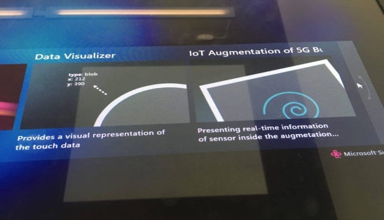
The application has been installed previously into the Microsoft Surface Shell, the application is automatically updated after it is compiled. Figure 12 shows that the application has been updated and can be executed from the Surface Shell.
Touch Controls
As explained in the Touch Gesture section (4.2), the multitouch support for the SUR40 has been heavily deprecated over the years, hence, the application only takes in single touch points, which causes the model to rotate accordingly. Due to the unreliability of the touch screen, buttons have been added to the array of buttons, which also rotate the model. These have been provided as a backup, in a scenario where the touch points cannot be processed properly.
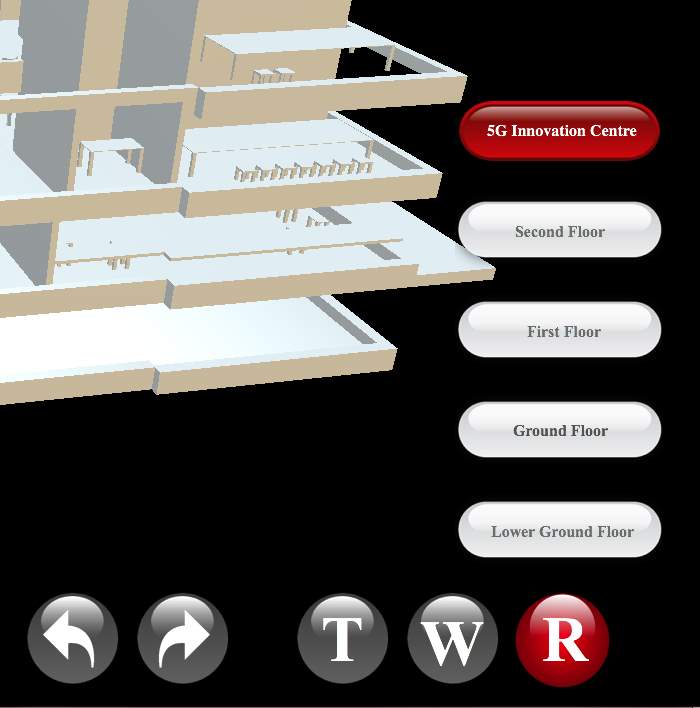
Figure 13. Screenshot of the application showing the control section, with buttons mapped to the rotational control of the model.
Comments
To summarise, the post-programming simulations were mostly positive, however, due to various factors, as explained earlier, the performance is not top notch. The features implemented were successful, and for those that have reliability issues, solutions were put in place, so as not to hinder the user experience.
There are several features which, due to the lack of time, could not be implemented, these ideas will be explored in the Innovation section.
7. Conclusion
7.1. Summary
The implementation of touch based controls for the IOT augmentation project, encountered a plethora of problems during development, however, the goal of being able to manipulate and control the model solely by the touch interface has been implemented.
In terms of touch control, the program has various touch options available on the On-Screen Display (OSD). These include;
The Various Viewing Options:
- Full Building: This mode shows the whole building, with all floors present.
- Lower Ground Floor: This option toggles the viewing of the basement floor alone.
- Ground Floor: This option toggles the viewing of the ground floor alone.
- First Floor only: This option toggles the viewing of the First floor alone.
- Second Floor only: This option toggles the viewing of the Second floor alone.
- Wall mode toggle: This button toggles the presence of the outer walls, which enhances viewing of the inner sections of the building.
The Model Rotation controls, in form of directional arrows. These controls can be seen in Figure 13 above, along with the various viewing options.
7.2. Innovation
As explained in the “Scopes and Objectives” section, the main idea of this project is to make an augmented version of the whole University of Surrey campus area. A few main areas still need to be considered for further development of this application. These areas include:
- Model Development.
The application currently has a model of the Institute for Communication Systems (5G Innovation Centre). For a more enriched experience to the end user, the models must be developed further with more precision as the current models have a few errors, and misplaced objects.
- Migration to an updated development environment.
During the initial development stages, the XNA framework was still under full support from Microsoft, but as of now, it is out of date, and has been heavily deprecated, hence, for further development, it is highly recommended that the program be exported to newer development engine. A few suggestions include; the Unity game engine, Cinder and Qt.
- Using the new and updated GestureWorks Library.
GestureWorks 2, a new and updated library, was released during the composure of this report. GestureWorks 2, is based on the C++ language, and is more efficient and stable compared to the older one used in this project [11].
- Migration of development to a newer Operating System.
One of this project’s limitation is that it was developed on Windows 7. Windows 7 is still being supported by Microsoft, but it initially did not come with a native touch control support, as opposed to Windows 8 and the more recent Windows 10, which are bundled with touch support for an easier experience.
8. References
| [1] | J. Slick, “Lifewire,” 2016. [Online]. Available: https://www.lifewire.com/what-is-3d-modeling-2164. [Accessed 1 January 2017]. |
| [2] | M. Rouse, “What Is?,” 2016. [Online]. Available: http://whatis.techtarget.com/definition/3D-modeling. [Accessed 31 December 2016]. |
| [3] | M. Rouse, “What Is,” 2010. [Online]. Available: http://whatis.techtarget.com/definition/spline. [Accessed 30 December 2016]. |
| [4] | University of Surrey, “Smart Cities,” 2016. [Online]. Available: http://www.surrey.ac.uk/eee/study/pd/courses/smart_cities.htm. [Accessed 1 January 2017]. |
| [5] | J. Maki, “Microsoft Developer Network,” 2013. [Online]. Available: https://blogs.msdn.microsoft.com/pixelsense/2013/04/08/touchtech-introduces-lima-for-samsung-sur40-windows-8-and-windows-7-multitouch-pcs/. [Accessed 31 December 2016]. |
| [6] | Microsoft Corporation, “TouchPanel.ReadGesture,” 2017. [Online]. Available: https://msdn.microsoft.com/en-us/library/microsoft.xna.framework.input.touch.gesturetype(v=xnagamestudio.42).aspx. [Accessed 2 January 2017]. |
| [7] | Microsoft Corporation, “GestureType Enumeration,” 2017. [Online]. Available: https://msdn.microsoft.com/en-us/library/microsoft.xna.framework.input.touch.gesturetype(v=xnagamestudio.42).aspx. [Accessed 2 January 2017]. |
| [8] | Shawn Hargreaves, “Touch input on Windows in XNA Game Studio 4.0,” 2010. [Online]. Available: https://blogs.msdn.microsoft.com/shawnhar/2010/09/09/touch-input-on-windows-in-xna-game-studio-4-0/. [Accessed 5 February 2017]. |
| [9] | Ideum, “GestureML,” 2015. [Online]. Available: http://www.gestureml.org/doku.php/gestureml. [Accessed 6 January 2017]. |
| [10] | Samsung Electronics, “SUR40 Venue Readiness Guide,” 2 December 2011. [Online]. Available: http://www.samsung.com/us/pdf/sur40/SUR40_Venue_Readiness_Guide.pdf. [Accessed 10 March 2017]. |
| [11] | Ideum, “GestureWorks 2,” 2017. [Online]. Available: http://gwiki.gestureworks.com/doku.php/start. [Accessed 10 May 2017]. |
9. Appendix
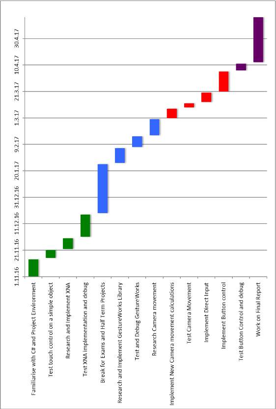 Gantt Chart
Cite This Work
To export a reference to this article please select a referencing stye below:
Related Services
View all


Related Content
All TagsContent relating to: "Technology"
Technology can be described as the use of scientific and advanced knowledge to meet the requirements of humans. Technology is continuously developing, and is used in almost all aspects of life.
Related Articles

DMCA / Removal Request
If you are the original writer of this dissertation and no longer wish to have your work published on the UKDiss.com website then please: