Characterisation and Optimisation of Mechanochemically Prepared AgOX/TiO2 Catalysts
Info: 21603 words (86 pages) Dissertation
Published: 15th Feb 2022
Tagged: Chemistry
Characterisation and optimisation of mechanochemically prepared AgOX/TiO2 catalysts for radical decarboxylative fluorination
Contents
Click to expand Contents
2. Abstract iv
3. Introduction 1
3.1 Methods of fluorination 3
3.1.1. Nucleophilic fluorination 3
3.1.2. Electrophilic fluorination 4
3.1.3. Radical fluorination 6
3.2. Heterogeneous catalysis 11
3.2.1. Methods of catalyst preparation 12
3.2.2. Wet impregnation 12
3.2.3 Sol immobilisation 13
3.2.4 Mechanochemical milling 13
3.3 Thesis targets 14
4. Strategy 15
4.1. Mechanochemical milling parameters 16
4.2. Methods of characterisation 18
4.2.1. X-ray photoelectron spectroscopy (XPS) 18
4.2.2. Temperature programmed reduction (TPR) 21
4.2.3. X-ray diffraction (XRD) 22
4.2.4. N2 physisorption 24
4.2.5. Scanning electron microscopy (SEM) 25
4.2.6 CO pulse titration 26
5. Experimental 28
5.1 Materials 28
5.2 Synthesis of AgOX Catalysts 28
5.3 Kinetic catalytic investigations 30
6. Results and discussion 32
6.1. Kinetic investigations 32
6.1.1 Effect of frequency 32
6.1.2 Effect of the number of ball bearings 38
6.2. Catalyst characterisation 40
6.2.1 X-ray photoelectron spectroscopy (XPS) 40
6.2.2. Temperature programmed reduction (TPR) 42
6.2.3. X-ray diffraction (XRD) 44
6.2.4. N2 physisorption 48
6.2.5. Scanning electron microscopy (SEM) 49
7. Conclusion 52
8. References 53
9. Appendix A 55
10. Appendix B 56
11. Appendix C 57
2. Abstract
Novel pathways that allow the formation of new C(sp3)-F bonds have been an objective that scientists have pursued for decades. Carbon-fluorine bonds are present in a variety of products that are vital globally, and their presence can have a profound effect on the chemical, biological and physical properties of a molecule. The recent introduction of the fluorinating reagent SELECTFLUOR® inspired a new range of fluorinating pathways to be unveiled, including a homogeneous silver-catalysed pathway for the design of new C(sp3)-Fbonds via radical decarboxylative fluorination. However, the utilisation of this pathway as a viable and inexpensive method of fluorination has been strained by a variety of factors, including the firm industrial preference of reusable heterogeneous catalysts. This inspired previous in-group researchers to develop a heterogeneous silver catalyst for decarboxylative fluorination reactions. Now, using a using non-traditional mechanochemical methodology, we herein describe the development and investigation of a range of ball-milled AgOX catalysts, including the characterisation and speciation of the silver species induced by utilisation of mechanochemical means.
3. Introduction
Since the first medicinal compound containing synthetic carbon-fluorine bonds was reported in 1957, chemists have sought to uncover novel pathways to efficiently and selectively perform fluorination reactions for the formation of new, pharmaceutically active compounds.[1] The introduction of a fluorine atom into an organic molecule has been shown to have a substantial effect on the physical, chemical, and biological properties on the molecule, and can therefore be a very useful tool in synthesising new pharmaceutical materials.[2] A telling illustration of the impact that fluorine has in the healthcare industry is that 20% of all pharmaceuticals contain fluorine, despite only 21 natural molecules with carbon-fluorine bonds known.[3] This attribute of fluorine in drugs is related to the enhanced activity that the fluorine bestows onto the organic compound, and can result in improved bioavailability, lipophilicity, metabolic stability, and increased protein-ligand interactions.[4] An example of recent progress in fluorination leading to new drug discovery is the enantioselective electrophilic fluorination synthesis of fluorooxindole – a promising agent in the treatment of stroke.[5] This discovery highlights the success that sustained research in C-F bond formation can deliver in the pursuit of new drugs to treat diseases.
Fluorine is also a vital component in several other important chemical industries outside of pharmaceuticals. In the polymer industry, for example, fluorine atoms are responsible for the extremely desirable non-reactivity, hydrophobicity, and low coefficient of friction in Teflon, which make it useful as a non-stick coating – a critical addition to cooking equipment.[6] As well as in the household, perfluorinated polymers similar to Teflon are used in the fuel cell industry. Nafion, a polymer produced from the addition of sulfonic acid groups into Teflon polymer structure, has been used in fuel cells for over 40 years due to its excellent thermal and mechanical stability.[7] There are many other fluoropolymers used in various commercial and industrial areas, including thermoplastics designed for use as coatings, and fluoroelastomers used for different moulded goods.[8] Although not currently available, fluorinated graphene is a new material that is presently commanding significant interest, with views to applications in both electronics and medicine. Although little is known about the chemistry of fluorinated graphene so far, it is thought to be a 2D counterpart of Teflon, sharing properties such as stability in air up to 400 °C.[9]
A major application for fluorination chemistry is in Positron emission topography (PET).[10] PET is an oncological treatment that is used to monitor metabolism and identify disease, with millions of scans being conducted every year. PET requires positron emitting radionuclides as detectors, with 18F in the form of 2-[18F]fluoro-2-deoxyglucose ([18F]FDG) preferred due to its low energy positron emission (which results in higher-quality 3D images) and 110- minute half-life of 18F. This half-life length is desirable for PET imaging, as it allows significant time for synthesis, administration to subjects, and imaging without being too disruptive to the patient. This is highly preferential to using 11C radionuclides, which have half-lives of only 20 minutes.[11]
The critical use of fluorination in these aforementioned medical and industrial sectors, as well as a dependence on fluorine in agrochemicals, perfluorinated solvents, and 19F NMR, has led to a huge industry demand for novel techniques of fluorination. Consequently, this pressure has stimulated research into the generation of new methods of fluorination, and resulted in the development of several new fluorinating reagents. This has inspired us to develop a highly active and selective heterogeneous silver catalyst for decarboxylative fluorination, through the optimisation of the synthetic parameters utilised in mechanochemical milling.
3.1. Methods of Fluorination
Modern published novel fluorination reactions tend to occur via one of two main reaction pathways: electrophilic or nucleophilic fluorination. This is due, in part, to the rapid progression in fluorination techniques that occurred with the development of S-F nucleophilic fluorinating reagents in the past few decades, and N-F electrophilic fluorinating reagents much more recently. Before this, progress was stunted due to the safety implications of the aggressive reagents needed for electrophilic and nucleophilic fluorination, such as perchloryl fluoride, which caused the pharmaceutical industry to shut down production of its fluorinated products following the death of two researchers. Heightened demand for more acceptable reagents that are less aggressive, less toxic, non-explosive and inexpensive, led to the development of diethylaminosulfurtrifluoride (DAST) – the first major S-F fluorinating reagent (other than sulphur tetrafluoride).[12]
3.1.1. Nucleophilic Fluorination
Since the 1970s, DAST has been used successfully in a number of highly efficient and selective fluorination reactions. It has been shown to be an effective deoxofluorination reagent that can work with a large range of substrates and can synthesise products at high yields (Figure 3.1).[13], [14] DAST is perhaps most renowned for its involvement in the synthesis of allylic fluorides from allylic alcohols.[15] Allylic fluorides are commonly found in many bioactive molecules and in radioactive tracers used for PET imaging. This means they are some of the most important compounds that can be synthesised through fluorination reactions. Despite the success of DAST in many deoxofluorination reactions and the key role it can play in the development of allylic fluorides, in more recent research DAST has been largely replaced by much less hazardous nucleophilic fluorinating reagents. DAST readily decomposes upon heating to form (NEt2)2SF2, a high boiling and explosive compound, meaning DAST can be dangerous to handle. DAST is also unable to perform regioselective or enantioselective allylic fluorination, instead providing a mixture of isomers. The utilisation of DAST for the site-specific monofluorination of alkyl alcohols also suffers from poor selectivity, with dehydrated and rearranged products also being produced. Consequently, safer crystalline alternatives are more prominently used in modern reactions, such as XtalFluor-E [16] and related reagents.[17] XtalFluor-E, for example is non-explosive and less moisture sensitive than DAST, whilst also being easier to handle due to its crystalline nature. It can induce deoxofluorination reactions that produce fewer byproducts and has also been found to be effective in other fluorination reactions such as aminofluorinations. [18] Interestingly, XtalFluor-E has been found to be effective in reactions outside of fluorination, where it is used as a surprisingly efficient coupling agent in the amidation of carboxylic acids.[19]
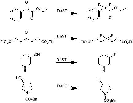
Figure 3.1: Examples of deoxofluorinations using DAST. From top: conversion of ethyl 2-oxo-2-phenylacetate to ethyl 2-difluoro-2-phenylacetate; conversion of diethyl 4-oxoheptanedioate to diethyl 4-difluoroheptanedioate; conversion of piperidin-3-ol to 3-fluoropiperidine; conversion of benzyl (S)-3-hydroxypyrrolidine-1-carboxylate to benzyl (R)-3-fluoropyrrolidine-1-carboxylate.
3.1.2. Electrophilic Fluorination
Whilst the area of nucleophilic fluorination experienced much success throughout the 1970s and 1980s, electrophilic fluorination has had a renaissance in recent years, following the development of 1-chloromethyl-4-fluoro-1,4-diazoniabicyclo[2.2.2]octane bis(tetrafluoroborate) (SELECTFLUOR®, F-TEDA-BF4).[20] Traditionally, highly toxic and strongly oxidising fluorine gas has been utilised as the source of electrophilic fluorine. However, the challenging nature of gaseous fluorine has meant that – for most functional groups – the approach of electrophilic fluorination had been unexplored. The development of SELECTFLUOR® (and to a smaller extent N-fluorobis(phenyl)sulfonimide (NFSI) [21]) has revolutionised the electrophilic design of reactions, and made highly selective and efficient procedures that can be tolerated by a number of functional groups possible. SELECTFLUOR® is much milder, safer, more stable, and less expensive to produce than previous electrophilic fluorinating agents such as elemental fluorine.[22] This ease of handling has led to widespread and more adventurous exploration of the capabilities of electrophilic fluorination. In recent years, SELECTFLUOR® has been shown to be adept at fluorinating a range of functional groups such as, enamines, aromatics, and alkenes. However, these methodologies are restricted to use with sp2 carbons and, much like DAST, are not suitable for site specific C(sp3)–F bond formation when using the fluorinating reagent alone. Unlike DAST however, SELECTFLUOR® has demonstrated an ability to work in tandem with an organocatalyst and therefore allow enantioselective monofluorination of alkyl compounds.[23] This methodology is unfortunately restricted to certain substrates – mostly α-carbonyl compounds – and more general and versatile methods are needed. As a consequence, novel electrophilic pathways for the selective formation of alkyl fluorides are highly desirable and is therefore an area of fluorination chemistry that is currently being given much attention.
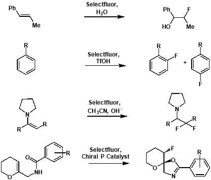
Figure 3.2: Examples of electrophilic fluorinations using SELECTFLUOR®. From top: formation of an alkoxyfluoride from an alkene [24]; formation of aryl fluorides from aromatics[25]; formation of a fluorinated carbonyl compound from an enamine [26]; formation of a fluorinated heterocycle using enantioselective fluorocyclisation [27].
3.1.3. Radical Fluorination
In addition to nucleophilic and electrophilic fluorination, a much less explored reaction pathway for fluorination transformations lies in radical fluorination. In radical reactions, homolytic or heterolytic fusion of the fluorine bond in the fluorinating reagent allows attack of the desired substrate, and formation of a C-F bond to occur. In contrast to the slower, more controlled reactions that occur in electrophilic processes, these pathways are generally very fast, but can be unselective and uncontrolled.
The development of synthetic methodologies involving use of radical reaction pathways tend to be ignored due to radical fluorination processes being perceived as uncontrollable. This is due to the reactions typically involving elemental fluorine. Since the fluorine-fluorine bond in F2 is very weak, and heats of formation of bonds between carbon and fluorine are very high, the reactions are extremely exothermic. The uncontrollable tag attributed to these reactions is inaccurate however, with the technique being applicable to many substrates when under suitable conditions.[28]
Despite the limited research featuring radical fluorination reactions in comparison to nucleophilic and electrophilic fluorination counterparts, there are a number of successful reactions that illustrate the promising nature the pathway possesses. In the past, radical pathways have been employed in the fluorination of aryl silanes using XeF2 as the radical fluorinating species.[29] This is a particularly interesting process as it demonstrates the ability of radical fluorinations to produce site-specific products, rather than uncontrollable perfluorinations.
Much more remarkably, radical decarboxylative fluorinations using F2 [30] and XeF2 [31],[32] have been demonstrated since the late ‘60s and early ‘80s respectively. Decarboxylative fluorinations allow formation of a C(sp3)-F bond in a way that is applicable to a wide-range of substrates, due to carboxylic acid groups being commonly available – both in natural compounds and through simple synthetic steps. This makes radical decarboxylative fluorinations a very exciting procedural tool for novel C-F bond formations. The reactions involving F2 and XeF2 are very inefficient however, and F2 and XeF2 are also highly toxic and unstable, further diminishing the applicability of these methods for use in industry. A lack of other suitable radical fluorinating reagents had meant that the area of radical fluorinations had been stalled up until very recently.
In the past few years, the ability of the N-F electrophilic fluorinating reagent SELECTFLUOR® to transfer fluorine to alkyl radicals has been demonstrated. Calculations reported by Sammis et al. indicated that the homolytic bond dissociation energies in the N-F bond are low enough to allow reaction with most alkyl radicals. These calculations were then confirmed with a publication detailing the fluorination of tert-butyl peresters in a radical mechanism using SELECTFLUOR® as a fluorinating reagent. [33] Whilst this work is commendable due to the pioneering aspect of the research – the first radical fluorination using SELECTFLUOR® – the perester substrates need to first be converted from carboxylic acids, and the applicability of the substrate system to other systems is unknown.
Although the work completed by Sammis et al. is unsuitable for most systems involving carboxylic acids, it facilitated progress in research on easier access to C(sp3)-F bonds via decarboxylative fluorination. The insight into the design of radical fluorinations involving SELECTFLUOR® reagent, prompted Li et al. to design a new synthetic strategy for decarboxylative fluorination with use of SELECTFLUOR® and a homogeneous silver catalyst.[34] This reaction shows remarkable chemo-selectivity and provides an efficient route to high-yielding products for a wide range of carboxylic acid substrates. In the same paper, Li et al. also proposed a mechanism for their Ag-catalysed decarboxylative fluorination, involving a Ag(III) intermediate. The Ag(I) species from AgNO3 is oxidised by SELECTFLUOR® to form the Ag(III)-F complex, which undergoes single electron transfer with the carboxylic acid to form the Ag(II)-F intermediate and an alkyl radical. Fluorine atom transfer then occurs from the Ag(II) complex to the alkyl radical forming the fluorinated product and regenerating the Ag(I) catalyst.
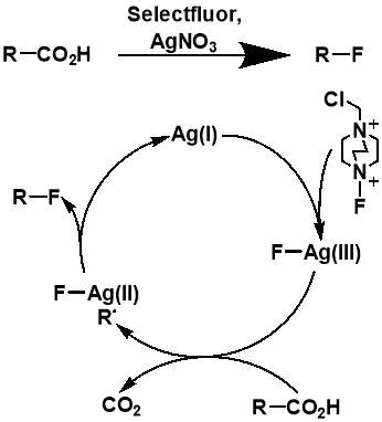
Figure 3.3: The AgNO3-catalyzed decarboxylative fluorination reaction published by Li et al. and the proposed mechanism of the fluorination. Adapted from the report by Li.
The importance of generating a further understanding of the innovative approach to the metal-catalysed fluorination designed by Li et al., and a desire to analyse the mechanistic conclusions that the work presented, led to two further mechanistic studies conducted. The studies, first a kinetic and spectroscopic study conducted by Flowers et al.,[35] and later a computational study using density functional theory conducted by Zhang,[36] both offered an alternative outlook to that initially proposed by Li et al. The study by Flowers II et al. suggested that the reaction instead initiates with the formation of a Ag(I) carboxylate, which is then oxidised by SELECTFLUOR® to produce a Ag(II) intermediate and a TEDA-BF4 radical cation. The Ag(II) carboxylate complex then oxidises the carboxylate, producing CO2 and an alkyl radical, as well as Ag(I) to continue the catalytic cycle. The alkyl radical produced then reacts with SELECTFLUOR® to produce the fluorinated product (Figure 1.4). The later paper by Zhang generally agreed with these mechanistic findings (Figure 1.5). Both studies dispute the Ag(III) mediated mechanism initially proposed by Li et al, with formations of both the Ag(II)-F and Ag(III)-F intermediates proposed to be unlikely. It also suggests that Ag(I) is the catalytically active oxidation state of Ag, with any Ag(II) or Ag(III) present in a catalyst likely to either have no or a detrimental effect on the reaction.
The research of Li not only demonstrates the feasibility of this radical-based approach, but also provides a useful mechanistic insight from which future catalytic developments can be made. However, for silver-catalysed fluorination reactions to become a widespread and applicable tool the cost of materials must be minimised. This means it is essential that the catalyst used can be regenerated. Whilst homogenous catalysts such as the AgNO3 catalyst used in the work by Li et al. cannot be captured and regenerated, it is possible for a supported solid catalyst to be extracted from the reaction and reused. A telling statistic of the benefits that heterogeneous catalysts offer over homogeneous catalyst is that of all industrial catalytic processes, approximately 80% are heterogeneous. [37] This inspired in-group researchers to develop a novel heterogeneous silver catalyst via solvent free mechanochemical milling for use in for decarboxylative fluorination reactions with SELECTFLUOR®.
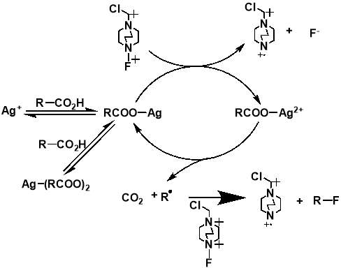
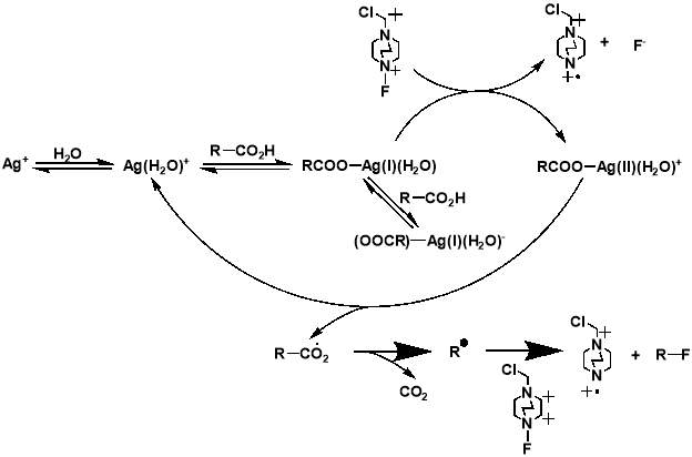
Figure 3.4 and 3.5: mechanisms for the decarboxylative fluorination of aliphatic carboxylic acids adapted from the proposed mechanisms published by Flowers II et al. (top) and Zhang (bottom).
3.2. Heterogeneous Catalysis
For reactants to be converted into products in a chemical reaction, there must be enough energy input into the system for it to overcome a minimum energy activation barrier. In catalysis, an alternate reaction pathway is offered that requires less activation energy, and hence allows an increase in the rate of reaction. The catalyst is also unaffected by this process, and as a result can continually participate in a reaction.
Catalysts can be separated into two distinct categories based on whether the catalyst exists in the same phase as the substrate. In homogeneous catalysis, both the catalyst and the substrate are in the same phase. In contrast, catalysts are considered heterogeneous when the catalyst and substrate are in different phases. Whilst homogenous catalysis can deliver excellent substrate selectivity and atom economy, most industrial processes do not consider it to be financially viable. This is mainly due to the difficulty of extraction of both the product and the spent catalyst for reuse. Without simple regeneration and reuse of the catalyst used in a given process, the time and cost involved is normally considered too exorbitant for industrial use. However, heterogenization of homogenous catalysts can allow these processes to become much more viable economically.
Heterogeneous catalysts tend to be solid materials, with the catalysed substrate being in either the liquid or gas phase. In the process of heterogeneous catalysis, the given substrate adsorbs onto the surface of the solid catalyst. The reaction proceeds through bond breaking and bond forming on the surface of the catalyst, before the product desorbs. The difference in phases between the substrate and catalyst mean the separation of the spent catalyst and the product post-reaction can be achieved through simple filtration. This is seen as a very advantageous characteristic of heterogeneous catalysis from an industrial perspective.
Heterogeneous catalysts normally consist of a precious, catalytically-active metal dispersed on a support material, typically a metal oxide, as nanoparticles. Consequently, catalytic performance is governed by atomic scale interactions between the nanoparticles, the support, and the environment. Through a greater understanding of these interactions and their effects on the catalytic properties, the active elements of the nanoparticles can be determined, and the mechanisms that control what elements of the nanoparticles are active in a given reaction can be investigated. With this knowledge, optimisation of the catalyst, and hence optimisation of parameters such as activity, selectivity, and durability can be understood and tailored. In general, single site control can be more difficult to contain in heterogeneous catalysis than homogeneous catalysis, and can lead to poorer reaction selectivity. This means optimisation of the preparation of the catalyst is very important. Therefore, consideration of the dispersion method for the nanoparticles, and the choice of catalytic support can be extremely significant in designing an industrially useful catalyst.
3.2.1. Methods of nanoparticle dispersion
The use of a support is essential in order to allow the catalytically active nanoparticles to be effective as a heterogeneous catalyst. For a number of reasons, nanoparticles must be prepared on a support material, with bulk alloy catalysts, such as Raney nickel, being very rare. First and foremost, supports help to ensure that the particles are dispersed effectively with little to no aggregation of particles. This is to guarantee that the nanoparticles have as high a surface area as possible and can therefore provide optimal catalytic performance. Similarly, the support must also have a high surface area to effectively ensure that the nanoparticles are dispersed as evenly as possible. Supports also help to reduce sintering – the aggregation of nanoparticles at very high temperatures below their melting point. These factors are incredibly important to consider when designing a catalyst and when deciding which method of nanoparticle dispersion will be the most effective for optimum catalyst performance.
3.2.2. Impregnation
Impregnation is generally considered to be the simplest method for making a supported catalyst, and has the advantage of being applicable for any porous support [38]. First, a solution of the catalytic metal is made up, and is then mixed with the chosen support. Upon the removal of the solvent and decomposition of the salt to its corresponding metal or metal oxide via calcination, nanoparticles of the metal nucleate on the surface of the support and within the pores. Despite the ease of this method, there are a number of disadvantages associated with the catalysts that are prepared in this manner. For example, the nanoparticles deposited with this technique tend to have a wide particle size distribution, with agglomerates common. Despite this, the impregnation method is widely used in industry due to the minimal waste obtained and the accurate nanoparticle deposition that the technique provides.
3.2.3. Sol-Immobilisation
Sol-immobilisation is a modern technique for preparing highly dispersed nanoparticles, that involves the use of a stabilising agent. [39] In this method, metals colloids are formed by reducing a solution of metal salts in the presence of a stabiliser. Use of the stabiliser prevents aggregation and results in supported metal nanoparticles which are finely dispersed and have remarkably small size distributions. [40] However, the stabiliser can often be difficult to remove, and any remaining stabiliser can affect the adsorption and desorption of a substrate with the active sites of the catalyst. [41]
3.2.4. Mechanochemical milling
A more unorthodox technique for the dispersion of nanoparticles is in mechanochemistry – the use of physical force to mix the metal precursor and support. Whilst in typical laboratory or industrial reactions, energy is input into the reaction system thermally, photochemically, or electrolytically, in mechanochemistry the reaction is induced via the direct absorption of mechanical energy.[42]While mechanochemical reactions have been conducted for centuries, mechanochemistry is increasingly being explored in research due to its ability to induce reactions between solids quickly and effectively using either none or catalytic amounts of a solvent.
There is growing evidence that use of solvent-free mixing techniques can produce extremely effective catalysts with advantages such as lower cost and environmental impact.[43] Despite this, the wet synthetic methods discussed above are used by default in both catalysis research and in industrial processes. Even with the low amount of research in this area, there have still been a number of cases where synthetic mixing has produced catalysts with higher activities than conventional solution-based methods.[44], [45]
Mechanochemical catalysis preparation can be as simple as the manual grinding of a chosen metal and support with a pestle and mortar, but can also extend to use of sophisticated ball-milling equipment. For typical laboratory syntheses, the catalytically active metal oxide is ground in a ball mill with the chosen support for a chosen time period, in a process that is occasionally followed by calcination. The high degree of mechanical energy exhibited on the prepared catalyst during grinding can have a variety of effects on the solid. These include, the generation of new interfaces, removal of the oxide film on the metal, heating, and changing of the particle size. [46] Because of the effects generated by mechanical activation, there has been substantial interest on how mechanochemical synthesis methods can affect catalytic properties.
In addition, mechanochemical research is currently very appealing because of the growing need to develop more sustainable reaction techniques. The solvent-free aspect of mechanochemistry is particularly appealing, due to the need to reduce our industrial dependence of solvents. Both solvent usage and recycling are becoming increasingly wasteful, environmentally hazardous and energy demanding with an estimated 85% of chemicals used in the pharmaceutical industry being solvents. [47]
3.3. Thesis target
The interesting features that mechanochemical mixing as a catalyst preparation technique can offer to novel heterogeneous catalysis has inspired its use in in-group research. The benefits that mechanochemical mixing have demonstrated in many catalytic systems, as well as the more environmentally-conscious route it offers, has meant that it has become a viable resource in the synthesis of catalysts.
Following the initial radical fluorination techniques pioneered by Li et al., previous in-group research focused on the development of a novel heterogeneous silver catalyst to generate greater industrial appeal for the technique than a homogenous catalyst. In addition to the development of a Ag/TiO2 heterogeneous catalyst via conventional sol-immobilisation techniques, pestle and mortar-based physical mixing techniques were also employed for catalyst preparation.
Due to the technique of physical mixing for catalyst development being in its relative infancy compared to other techniques, and the overall scope of the technique being unknown it is very important to thoroughly investigate the mechanisms of control the technique offers. This has inspired us to develop a strategy to determine the characterisation the AgOX catalysts prepared using mechanochemistry, and with this knowledge, allow full control over the active site speciation via tuning of the mechanochemical parameters. This will enable the determination of the optimal synthesis conditions for dispersed AgOX in terms of obtaining maximum concentration and activity of Ag(I). Through this analysis, the research will deliver an array of information that will not only benefit catalysis for fluorination reactions, but also the field of the physical mixing for catalyst preparation as a whole.
4. Strategy
The previous Hammond group research on the development of a heterogeneous silver catalyst for decarboxylative fluorination inspired our investigation into the use of mechanochemical mixing techniques as an alternative method of catalyst synthesis. In the aforementioned research, sol immobilisation was utilised for the preparation of a highly active and selective Ag/TiO2 catalyst for radical fluorination with SELECTFLUOR©. In addition, pestle and mortar induced physical mixing techniques were found to be effective in synthesising similarly active catalysts. Whilst cheap and convenient, there are a number of issues associated with the use of a pestle and mortar to initiate a reaction, including impracticality, and most importantly limited reproducibility. Considering this, it was decided that ball milling as a means of catalyst preparation could be utilised in the optimisation of the catalyst. Use of a programable ball mill allows a greater control of conditions offered and so a stronger influence on the composition and speciation of the AgOx catalysts. An aim was therefore set to develop a range of AgOx catalysts using ball milling, and tune the conditions used in order to obtain the maximum concentration of Ag(I), and hence the highest possible activity.
It was postulated that achievement of this target would require significant tailoring of mechanochemical synthesis parameters and numerous characterisation techniques. Therefore, a plan-of-action was outlined to detail the steps needed to ensure a thorough investigation of all mechanochemical variables, and a full characterisation of all surface species. The plan is outlined in the steps listed below:
1. Optimisation of mechanochemical synthesis parameters:
- Milling Frequency – 3 Hz, 7.5 Hz, 12 Hz, 15 Hz, 18 Hz, 22.5 Hz and 30 Hz
- No of ball bearings – 2, 4 and 8
- Ball bearing size – 5 mm, 10 mm and 14 mm
- Jar and ball material – Zirconia and stainless steel
- Reaction time – 10 min, 15 min, 20 min, 25 min and 30 min
2. Characterisation of catalysts synthesised via mechanochemistry:
- Speciation/Oxidation state – XPS, XRD, TPR
- Surface characterisation – SEM, N2 Physisorption
- Number of active sites – CO pulse titration
Implementation of this plan would allow comparison of the method of physical mixing for catalyst preparation with the established method of sol immobilisation. This investigation would therefore promote an in-depth understanding of mechanochemistry for catalyst development, and an insight into the possible scope of the technique.
4.1 Mechanochemical Milling Parameters
The term mechanochemistry refers to a reaction ‘that is induced by the direct absorption of mechanical energy’ and directly denotes the use of shearing, stretching or grinding to cause the initiation of a chemical reaction. The majority of important mechanochemical reactions proceed through interfacial shear, which is the mechanochemical removal of films of adsorbed layers of reacted lubricant additive that forms on a surface to reduce friction or wear. This type of force, as well as the use of grinding to break up materials and reduce particle size are the main forces used to initiate mechanochemical reactions via ball milling [48].
Ball milling can be an effective tool for performing reactions, and many mills contain several variables that can be tuned to allow the most appropriate settings for the reaction being run. These include typical single and double armed shaker mills designed for shearing small amounts of reactants, and planetary mills which are designed for a larger laboratory scale. Each of these mills offer their own advantages and disadvantages, however both suffer from not being designed for chemical reactions. Instead, their intended manufactured use is for the processing of materials – the grinding and homogenizing of materials down to smaller particle sizes for applications in processes such as DNA recovery. Consequently, mills are not equipped with many technological advances that are commonplace in more conventional areas of chemistry. This includes the absence of any form of temperature monitoring, and a lack of in situ monitoring equipment as standard. As used in the previous Hammond group research, mechanochemical reactions can also be conducted using a mortar and pestle. However, in order for the reaction conducted to be as reproducible as possible, the use of mortar and pestle is rarely preferred to a mixer mill.
For this investigation, the Retsch Mixer Mill MM 400 [49] (Figure 4.1) has been used for all milling reactions. This is a double armed mill capable of swinging two ball milling jars laterally at frequencies of up to 30 Hz, making it an effective instrument for investigation of frequency. The lateral movement causes the balls inside the closed jars to shake violently, impacting the bottom and lid of the jars, as well as the reactants in the jars. This type of mill can be used to efficiently perform two small-scale reactions quickly and can be an effective way to screen a reaction before attempting a medium-scale synthesis.
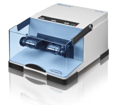
Figure 4.1: A Retsch Mixer Mill MM 400
The types of materials that can be used for jars and ball bearings are metal alloys (such as stainless steel) and inert inorganic substances (such as zirconia and tungsten carbide). Organic materials such as Teflon and PMMA have also been used as materials for jars. These jars tend to be cylindrical, with rounded inner edges to permit rapid ball movement and reactant mixing. Because of this variety of milling media, reactions can be quickly and easily tailored via the changing of equipment. For example, PMMA milling media could be changed for tungsten carbide milling media to increase the force of impact by using a material with a higher density. There are also a large variety of ball bearing materials available in a range of sizes and weights. This variety can allow the swapping of one large ball bearing for two smaller ones, and thus allow the enhancement of the mixing process, whilst keeping the overall weight of the jar and other media relatively constant. This means size, weight, and number of ball bearings, as well as jar and ball bearing material, can be customised very simply to achieve a particular reaction goal. For this investigation into mechanochemical milling parameters, only stainless steel and zirconia have been examined. This is because stainless steel is the most commonplace milling material, and so development of a catalyst using this material is desirable. However, as lengthy milling can sometimes lead to metal contamination, zirconia, a material with a similar density to stainless steel has also been examined.[50]
The effects of these milling parameters and the variety of other tailorable factors that can drastically change a reactions outcome should be carefully monitored and considered when performing a milling reaction. Examples of such factors include: identity of milling media, number, size, and weight of ball bearings, total weight of materials in the jar, ball-to-reactant ratio, total milling time, and the frequency that the milling process is performed. While some research has been performed into the effects of the mechanochemical parameters in the context of organic and inorganic synthesis, there has been very little investigation into these factors in heterogeneous catalysis. This work attempts to provide a novel and interesting insight into the effect of these parameters on the surface species of a catalyst, and how this affects the activity of the species.
4.2. Methods of characterisation
To gain an insight into the effects of the tunable mechanochemical parameters, significant characterisation of the milled AgOXspecies is required, including characterisation of oxidation state, particle size, and the number of active sites. An understanding of a variety of sensitive and informative characterisation techniques are therefore needed for this analysis to be successful. A number of techniques that are appropriate for an understanding of the AgOX catalysts developed are outlined in this section.
4.2.1. X-ray photoelectron spectroscopy (XPS)
XPS is a commonly used technique that allows the investigation of the surface of a solid by measurement of the binding energy of photoelectron peaks. Through this, detailed information about elemental composition, chemical state and electronic state of the elements at surface can be attained.
Heterogeneous catalytic processes are characterised by a number of separate steps that take place at the surface of the catalyst, in the form of surface diffusion, adsorption, formation of intermediates, and desorption of products. Investigation of the interfaces that are induced in a catalytic reaction, and the electronic and chemical properties of the species present, has prompted utilisation of XPS as an effective characterisation tool. XPS is also heavily used as a tool for characterisation of catalysts in ex situ identification of surface species. It is for this information that the various mechanochemically synthesised AgOX catalysts used in our investigation have been characterised.
The basis of XPS is the photoelectric effect. In XPS experiments, spectra are obtained by irradiation of the surface of material with an X-ray beam with sufficient energy to cause the ejection of electrons. The kinetic energy (EK) of the electron emitted is detected, and the binding energy (EB) can then be calculated using the equation below. In order to account for measurement of the binding energy at the Fermi level rather than the vacuum level, the work function of the metal is included.
EK = h EB Φ (1)
Where h is the energy of the initial x-ray beam (typically >1200 eV) and Φ is the work function of the metal sample measured.
A photoelectron spectrum is yielded by plotting the spread of kinetic energies as a function of the photoelectron flux. Peaks are recorded at accessible energy levels of the sample analysed which, if the energy is sufficient, may cover many different levels of the sample. These characteristic peaks therefore enable the identification and quantification of all surface elements. The basic elements of an XPS experiment are shown in Figure 2.2 below:

Figure 4.2: Schematic of an XPS experiment
All materials that contain orbital levels with an angular momentum quantum number greater than zero undergo spin-orbit coupling. This means coupling will occur in all p, d and f levels between the fields of spin (s) and angular momentum (l), leading to two or more peaks observed. The total angular momentum is calculated using j = |l + s|, with multiplicities proportional to (2j + 1). This means for the 3d orbital of silver, two peaks will be observed due to j values of 52 and 32, with an intensity ratio of 3:2.
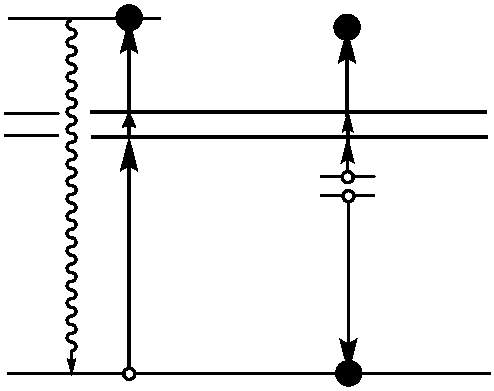
For many metals, Auger peaks can allow a much simpler investigation on the effect of oxidation. Auger peaks are observed in the photoelectron spectrum and result from energy released in an Auger Emission. This arises from the formation of a core hole after photoemission of a core electron. The core hole (1s) is rapidly neutralised by electrons from higher energy levels (2s), causing both radiant (fluorescence) and non-radiant (Auger emission) decay processes (2p), with the proportion of Auger transitions increasing as the atomic number (Z) of the sample increases. This process is illustrated in Figure 2.3 below.


Φ
Figure 4.3: A diagram illustrating the Auger process in the process of the photoemission of an electron
Auger peaks can assist in the identification of the oxidation state for many metals where core levels are not sensitive enough to lead to measurable chemical shifts in a change in oxidation. This is due to Auger transitions involving valence electrons universally displaying larger chemical shifts than the peaks observed from photoemission. [51] [52]
It is because of this that XPS is indispensable in determining the speciation of the AgOX catalysts synthesised mechanochemically. While the Ag(3d5/2) peak shows very little distinguishable shift when changing oxidation state from metallic silver to Ag(I), the Auger peaks show a much more significant shift, and thus are satisfactory for identification means. This makes XPS a substantially important tool for identifying Ag(I). In addition, the relative concentration of each Ag species can be determined quantitively via integration of the relevant peak, meaning that XPS can also be used effectively in determining the composition of each Ag catalyst.
4.2.2. Temperature-Programmed Reduction (TPR)
TPR is another method that can be used effectively in the characterization of metal oxides on a support. TPR allows monitoring of the reduction behaviour of a catalyst as a function of temperature and so can allow the characterisation of the redox properties of certain catalytic materials. This can also allow an understanding of the surface reactivities between the catalyst and the gaseous environment it is in and any gas-surface interactions. The redox properties of the mechanochemically synthesised AgOX catalysts, and the desire to characterize and identify the presence of any Ag(III) species involved in the catalyst, means TPR will provide very useful information for the optimisation of the catalyst for decarboxylative fluorination reactions.
In TPR experiments, a reducing gas mixture (e.g. 1% H2 in argon) is pumped over the catalyst, while the temperature is increased linearly. As the temperature rises, the rate of reduction is monitored continuously by measuring the concentration of the reducing gas mixture at the outlet. This allows determination of the amount of H2 consumed in the reduction process, meaning the average oxidation state of the material following reduction can be calculated.

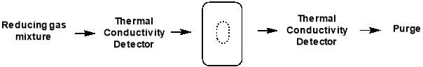
Figure 4.4: schematic of TPR setup
The signals obtained from TPR analysis are associated with the different reducible species present in the sample and any broadening or shifting of the signals may depend on interactions of the reducible species and the support of other elements present. Any changes in the sample used are clearly exposed by a change in the position, shape or intensity of a TPR feature, illustrating the high sensitivity of this method of characterisation. However, TPR cannot provide the highly detailed and specific analysis that techniques of diffraction or spectroscopy can, and it is much more beneficial to accompany the data obtained with other sources of information. In conjunction with XPS and XRD, TPR will allow determination of the silver oxide species present in each catalyst.
4.2.3. X-ray Diffraction (XRD)
XRD is a rapid analytical technique that is primarily used for the identification of the crystalline phases of a material and can produce information on unit cell orientations. This is useful for heterogeneous catalysis, as XRD can allow precise identification of the metal oxide phases present and other components of the bulk structure and composition. However, as many catalysts are formed of crystallites of varying size and orientations, XRD analysis can be limited to identification of specific lattice planes.
In XRD experiments, an x-ray source beams electrons at a target crystalline material causing inelastic scattering. The material acts as a three-dimensional diffraction grating, diffracting the photons of the incident beam at angles characteristic of defined lattice parameters. The diffracted photons are then collected by an area detector and, for peaks to be generated, constructive interference of the diffracted photons must occur. In order for constructive interference to transpire, the distance travelled by the x-ray beam must be an integer of its own wavelength. For a randomly aligned, crystalline powder sample, there is an adequate number of specific directions where a regular array of atoms will scatter constructively, illustrating the effectiveness of powder samples for the generation of intense diffractograms.
The distance between adjacent planes in a lattice is termed the d-spacing, and acquisition of this figure is essential for calculation of the lattice parameter of the material. The d-spacing of the sample material can be obtained using the Bragg equation listed below:
nλ = 2dsinθ (2)
Where n is a positive integer, λ is the wavelength of the incident x-rays, d is the d-spacing (the distance between two adjacent lattice planes (Å)), and θ is the scattering angle relative to the normal reflectance plane.

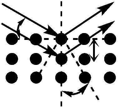
Figure 4.5: Constructive interference of two scattered waves by scatterers separated by interplanar distance d. The incoming waves are deflected by an angle 2θ, producing a reflection spot in the diffraction pattern.
The lattice parameter, a measurement of the physical dimensions of a unit cell in a lattice, can be utilised to indicate the presence of additional species in a sample. This can be useful when measuring a series of similar chemicals, such as a series of catalysts. Any variation to the average lattice parameter measured can suggest a composition change between samples. This can then be measured using the equation below:
d=ah2+k2+l2 (3)
Where d is the d spacing (Å) with respect to the miller planes h, k, and l, and a is the lattice parameter (Å).
An additional application to catalyst characterisation that XRD can be used for is in average crystallite size determination. This allows the determination of structural and textural properties of catalytic materials and is an important method of characterisation of all materials greater than 3 nm in size. Crystallite size can be measured using line broadening analysis. While larger crystallites have significant long-range order, and therefore give sharp peaks in a diffractogram, smaller crystallites (>100 nm) produce narrow and blunt peaks due to the incomplete destructive interference of reflected x-rays in directions where they are out of phase. Information on the size of crystallites can be determined using the Scherrer equation, stated below:
Where L is the dimension of the crystallite in the direction perpendicular to the reflecting plane, K is the crystallite shape factor (usually 1), λ is the wavelength of the incident x-rays, β is diffraction broadening (radian), and θ is the scattering angle relative to the normal reflectance plane. 51
Through each of these calculations, XRD will provide important information on the oxide phases potentially present in the Ag catalysts measured, namely Ag2O, Ag2O2, Ag0, and on the structural properties of these materials.
4.2.4. N2 Physisorption
N2 physisorption is an essential technique in the process of evaluating structural changes in a series of catalysts. Use of this technique provides specific surface area measurements of each chosen sample, based on the quantity of N2 adsorbed due to physisorption.
Physisorption is a process that is fundamentally governed by van der Waals interactions between a gas and the surface monolayer of an adsorbate sample. In terms of catalysis, this can be used to determine the total surface area of a catalytic material, not just the active site coverage as chemisorption is limited to. This process of physisorption does not change the electronic structure of the gas molecule in the interaction. This is unlike chemisorption, where the electronic structure of the gas molecule is modified to allow for covalent or ionic bond formation.
To determine the total surface area of the sample measured, an adsorption isotherm must be generated. In N2 physisorption, isotherms are produced by introducing known volumes of N2 at several different pressures and measuring the amount of N2 adsorbed. This data can then be used to plot an adsorption isotherm, of which the characteristic shape of the line trend can provide detailed information on the material. There are six distinct characteristic isotherm shapes exhibited by materials that each indicate whether adsorption takes place only on the monolayer or on multiple layers below the surface monolayer. The isotherms also reveal the point where the surface monolayer is fully saturated with N2 adsorption and multi-layer adsorption begins. Knowledge of this point is essential for use of the Brunauer–Emmett–Teller (BET) theorem, which determines the surface area of a material at pressures up until this saturation point, according to the below equation:
PVaP0-P=1VmC+C-1VmCPP0 (3)
Where P is the gas pressure, P0 is the saturation pressure, Va is the total volume of gas adsorbed, Vm is the volume of the monolayer, and C is a constant related to the affinity of N2 to the adsorbate.
Use of this equation allows a value for the volume of monolayer of the chosen material to be calculated. From this information, the surface area of the material can be calculated using the equation as follows:
SBET=VmσNamV (4)
Where SBET is the specific surface area of the sample, σ is the molecular area of N2, Na is Avogadro’s number, m is the mass of the sample, and V is the molar volume of the adsorbate gas.
In this investigation, surface area will provide another vector of comparison between each series of silver catalyst produced mechanochemically, and so an additional parameter that can be used to determine the optimum conditions for preparation of the most active catalyst for decarboxylative fluorination. 51
4.2.5 Scanning Electron Microscopy (SEM)
SEM is a surface sensitive technique that allows the characterisation of the morphology of surface structural features in bulk materials. Use of this technique provides high quality surface imaging that contains information on the surface topography and composition through electron interactions.
In SEM, a series of electromagnetic lenses are used to focus a beam of electrons at a sample. On interaction with the surface of the sample, the electrons are deflected at various angles and collected by a detector, producing a variety of signals based on the type of interaction with the sample surface. Secondary electrons, produced via the inelastic scattering of the primary beam of electrons, are responsible for the initial SEM image formed. These electrons are generally of low energy as they originate from only a few nanometers below the sample surface, and yield the highest resolution images. The emission of secondary electrons allows mapping of the topography of the sample as the secondary electron generation is dependent on sample orientation. Regions of the sample perpendicular to the beam appear the brightest, and so by controlling secondary electron generation the contrast of the image can be optimised.
High energy backscattered electrons are also generated through the interaction of the primary beam with the surface sample. These electrons are emitted from much deeper regions of the material than secondary electrons, and so yield much lower resolution images. The images generated from detection of the backscattered electrons can give information on the elemental composition of the sample. These images are often paired with the spectra produced from the detection of characteristic x-rays, another form of signal detected from the interaction of the primary electron beam with the sample. Characteristic x-rays are emitted when an inner shell electron is removed from an atom in the sample by the electron beam, causing a higher-energy electron to fill the shell and release energy. The spectra produced can be used to identify the elemental composition, along side back scattered electrons.
SEM will allow characterisation of the AgOX catalysts synthesised through ball milling, in terms of the surface structural features of the catalysts. 51
4.2.6. CO Pulse Titration
The pulse titration technique is an effective tool for calculating the number of active sites located on a catalyst surface. Catalyst surfaces tend to be sufficiently reactive to form strong bonds with small gas molecules at certain active sites in processes called chemisorption. By reacting a known concentration of gas with a catalyst surface, and assuming only one molecule of gas interacts with one active site, it can be possible to detect the number of active sites on the catalyst surface. This is the basis of pulse titration.
In pulse titration, a probe gas, such as H2, CO, or N2O, is pumped through a tube containing the catalyst of interest at a chosen rate. On each pulse of the gas pumped, probe gas molecules are adsorbed onto the surface of the chosen catalyst until the catalyst is full saturated. The remaining gas is then collected at the output of the tube and inputted into a chromatographic detector. The first or first few pulses will generate a small or zero area signal, due to the gas being completely adsorbed. As the number of pulses increases, the number of unoccupied active sites decreases, and thus the signal generated will increase in intensity, by more CO flowing into the detector. After a certain number of sequential pulses, none of the pulsed gas will be adsorbed and equivalent detector responses will be recorded, signalling full saturation of the surface-active sites. The active site density (number of active sites per volume) of the catalyst can then be determined using the below equation – assuming each adsorbed probe gas molecule corresponds to one active site.
Active site density= PVRTnsm∑i=1n1-AiAst (4)
Where P is the pressure of the pulse gas (atm), V is the volume of the injection loop used in the experiment (dm3), R is the gas constant (0.082 dm3 atm K−1 mol−1), T is the temperature of the pulse gas (K), nsis the ratio of pulse gas molecules to surface atoms (for CO, ns = 1), m is the mass of catalyst sample used (g), n is the total number of pulse injections, Ai is the area of the peak of CO detected after pulse i (mV.s) and Ast is the area of the peak of CO detected after saturation (mV.s).
Knowledge of the active site density will allow simple comparison of the activities of all mechanochemically synthesised AgOX catalysts. 51
5. Experimental Section
5.1. Materials
For preparation of the catalytic AgOX materials and in the subsequent investigation of the activities of the catalysts in radical decarboxylative fluorination reactions the following materialswere used.
Table 5.1: Materials used in preparation of AgOX catalysts and in decarboxylative fluorination reaction
5.2 Synthesis of AgOX Catalysts
The synthesis of the AgOX catalysts was performed in a Mixer Mill MM 400 (Retsch®) according to the following synthetic procedure. Silver(I) oxide (>99%, Sigma Aldrich®) was added to Titanium(IV) oxide, AeroxideTM P25 (>99%, Aerosil®) with masses of each solid weighed to achieve the required metal loading weight percentage with respect to silver, calculated using equation 3.1. The two solids were placed in a 25 mL milling jar with n ball bearings and milled at the chosen frequency for 20 minutes, before a solid powder was obtained. The 15 catalysts synthesised with this procedure have been tabulated in table 3.2 below.
Mass of silver= Mr(Ag2O)2 × Ar(Ag)× % weighting (5)
Mass of titania= 1 g-% weighting of silver (6)
| Catalyst Number |
% Ag | Support Material | Number of ball bearings | Size of ball bearing(s) (mm) | Frequency (Hz) |
Jar and Ball material |
| 1 | 1 | TiO2 | 1 | 10 | 3 | Stainless steel |
| 2 | 1 | TiO2 | 1 | 10 | 7.5 | Stainless steel |
| 3 | 1 | TiO2 | 1 | 10 | 12 | Stainless steel |
| 4 | 1 | TiO2 | 1 | 10 | 15 | Stainless steel |
| 5 | 1 | TiO2 | 1 | 10 | 18 | Stainless steel |
| 6 | 1 | TiO2 | 1 | 10 | 22.5 | Stainless steel |
| 7 | 1 | TiO2 | 1 | 10 | 30 | Stainless steel |
| 8 | 1 | TiO2 | 2 | 10 | 15 | Stainless steel |
| 9 | 1 | TiO2 | 4 | 10 | 15 | Stainless steel |
| 10 | 1 | TiO2 | 8 | 10 | 15 | Stainless steel |
| 11 | 1 | TiO2 | 1 | 10 | 3 | Zirconia |
| 12 | 1 | TiO2 | 1 | 10 | 7.5 | Zirconia |
| 13 | 1 | TiO2 | 1 | 10 | 15 | Zirconia |
| 14 | 1 | TiO2 | 1 | 10 | 22.5 | Zirconia |
| 15 | 1 | TiO2 | 1 | 10 | 30 | Zirconia |
Table 5.2: AgOX catalysts synthesised via mechanochemical ball milling for use in radical decarboxylative fluorination reactions.
For conciseness, in the results and discussion section (section 6) all catalysts will be referred to with the following nomenclature:
AgOX/TiO2 (nHz, mbb, a)
Where n is the frequency of the milling process that the catalyst was synthesised, m is the number of ball bearings used in the synthesis, and a is the type of material used in the milling media for that synthesis (SS for stainless steel or Zr for zirconia). For example, catalyst number four in Table 5.2 will be henceforth recorded as: AgOX/TiO2(15Hz, 1bb, SS)
5.3. Kinetic Catalytic Investigations
In order to monitor the activity and the stability of the AgOX catalysts synthesised, a range of decarboxylative fluorination reactions were performed. In each of these reactions, the conversion of a carboxylic acid substrate to the fluorinated product was monitored through the analysis of structured, periodic samples from the reaction vessel as the reaction progressed.
Each of these reactions utilised 2,2-dimethylglutaric acid as the carboxylic acid substrate (as used in the first silver-catalysed radical decarboxylative fluorination reaction with SELECTFLUOR®) and were performed in a 10 mL round-bottomed flask at 30 °C with stirring (700 rpm). The general reaction conducted is detailed in the reaction scheme below:
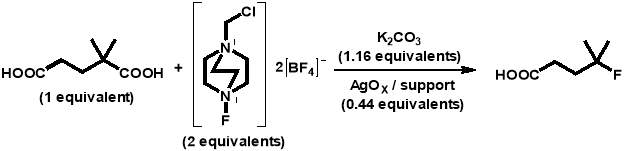
The above reaction was carried out in each of the catalytic tests as follows.Potassium carbonate (0.0320 g, 0.000231 mol), SELECTFLUOR® (0.1417 g, 0.000400 mol), and the AgOX catalyst (0.1000 g, 0.000088 mol) were placed into a 10 mL round-bottomed flask and flushed with nitrogen for 5 minutes. A solution of 2,2-dimethylglutaric acid (4 mL, 0.0025 M) was added and samples of 0.1 g were taken periodically for analysis. Each sample was centrifuged to separate the catalyst, and 0.1 mL of the solution was added to a solution of 1,4-succinic acid (0.5 mL, 0.003 M). The 1,4-succinic acid was used as an internal standard and so the masses of all reaction solution and standard solution aliquots were measured to ensure reliable data was obtained. The samples were then analysed using high performance liquid chromatography (HPLC) (Agilent 1220 Infinity LC) with a UV-Vis detector.
HPLC was used to analyse the fluorination reaction samples, as it is a rapid and reliable technique that can identify and quantify multiple components present in a mixture. In the previous Hammond group research, HPLC had been utilised effectively for the identification of sample components from silver-catalysed radical decarboxylative fluorination reactions. Because of this, several experimental calibrations and all product identifications had already been completed. This information is displayed in Table 3.3 below:
For the kinetic reactions, a specific acid separation column (Agilent MetaCarb 87H Column 250 x 4.6 mm) has been used, due to the degradation effects that the carboxylic acids used in the reaction would have on a standard HPLC column. An aqueous solution of phosphoric acid (0.1 wt %) in ultrapure HPLC grade water was used as the eluent with a flow rate of 0.4 mL min-1, and the oven was maintained at 60 °C.
6. Results and Discussion
6.1. Kinetic Investigations
6.1.1. Effect of frequency
To begin the investigation into the effect of the alteration of mechanochemical milling parameters on catalyst performance, a range of catalysts at different milling frequencies (3 – 30 Hz) in stainless steel milling media (catalysts 1-7 in Table 5.2) were synthesised. In doing this, preliminary information on the effect of impact on catalyst performance would be obtained, gaining an insight into the extent that the variation in frequency has on the properties of each catalyst. In addition, the frequency used to prepare the most active catalyst would act as a benchmark for the investigation of other parameters, such as the effect of the number of ball bearings, and the ball bearing size. This investigation into the effect of frequency would also give the first insight into whether it is possible to achieve the same activity from catalysts prepared using ball milling as it is from catalysts produced using more conventional techniques, like sol immobilisation.
Using the reaction procedure outlined in section 5.3, the activity of each catalyst was measured as a function of 2,2-dimethlyglutaric acid (DMGA) conversion against time. The results of these experiments are shown graphically in Figure 6.1.
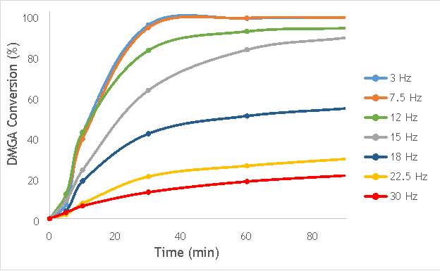
Figure 6.1: A graph showing the conversion of 2,2-dimethlyglutaric acid against time for seven catalysts synthesised at seven different milling frequencies in stainless steel.
As shown in Figure 6.1, there is a distinct trend of catalytic activity decreasing with each increase in milling frequency. The catalysts synthesised by milling at the two lowest frequencies (3 Hz and 7.5 Hz) show the highest conversion of 2,2-dimethlyglutaric acid (DMGA) and reach peak conversion of almost 100% after only 40 minutes of reaction time. On the other hand, the catalysts synthesised at the two highest frequencies (22.5 Hz and 30 Hz) are unable to reach even 30% conversion of DMGA after 90 minutes of reaction time.
Whilst this data provides interesting figures on the peak conversion that can be reached by each catalyst, using this information independently is insufficient for determining the most appropriate catalyst for use in radical decarboxylative fluorination reactions. This information must be paired with data on the stability of each catalyst in order to determine the heterogeneity of the catalytic system. Catalysts with low stability can leach into the reaction mixture with the possibility of contaminating the product and impacting the turnover frequency (TOF) of the catalyst. Thus, the active species (homogeneous or heterogeneous) with the more substantial contribution to the catalytic activity must be identified before the optimal catalyst can be determined. It was therefore decided to analyse a selection of the most active catalysts shown in Figure 6.1 by their homogeneous contribution to the reaction rate using a hot filtration experiment.
The hot filtration experiment can be utilised to assess the heterogeneity of a catalyst, by quantification of the homogeneous contribution to the activity observed. In a hot filtration experiment, the catalyst is removed from the reaction after a certain period of time, with the reaction left to continue. Any further monitored increase in reactant converted would indicate the presence of catalytically active species that had leached into the reaction mixture.
In this investigation, the reaction was carried out exactly as described in section 3.3, but with the catalyst removed after 5 minutes of reaction time. The reaction was then monitored for a further 25 minutes, in order to measure the performance of the reaction in the absence of the catalyst, and therefore quantify the homogeneous contribution to the reaction that each catalyst has. This procedure was carried out with three of the catalysts shown in Figure 6.1 with the highest activities (7.5 Hz, 12 Hz, and 15 Hz) and the results for each of these experiments are detailed in Figure 6.2, 6.3, and 6.4 below.
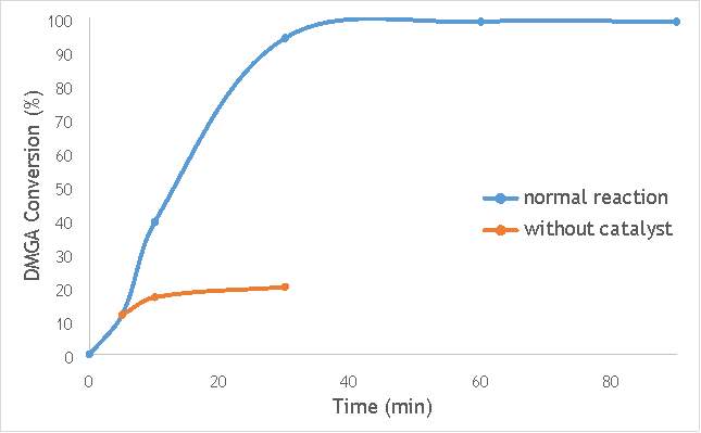
Figure 6.2: A graph comparing the conversion of 2,2-dimethlyglutaric acid (DMGA) against time with catalyst AgOX/TiO2(7.5Hz, 1bb, SS) in the normal reaction andafter hot filtration of catalyst.
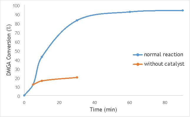
Figure 6.3: A graph comparing the conversion of DMGA against time with AgOX/TiO2(12Hz, 1bb, SS) in the normal reaction andafter hot filtration of the catalyst.
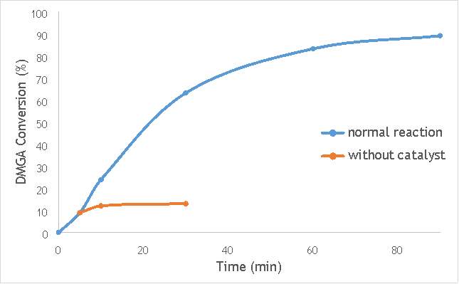
Figure 6.4: A graph comparing the conversion of DMGA against time with AgOX/TiO2(15Hz, 1bb, SS) in the normal reaction andafter hot filtration of the catalyst.
The graphs (Figures 6.2, 6.3 and 6.4) show a distinct increase in DMGA conversion on as milling frequency increases, even after removal of the catalyst. Upon the filtration of catalyst AgOX/TiO2(7.5Hz, 1bb, SS), the conversion of DMGA increases from 11.5% to 20%, a total increase in conversion of 74%. However, for the AgOX/TiO2(15Hz, 1bb, SS) catalyst the conversion of DMGA increases from 9% to 13%, a much lower total increase in conversion of just 44%. Catalyst AgOX/TiO2(12Hz, 1bb, SS) showed a total increase in conversion of 66%.
This data indicates the extent of the homogeneous contribution of each of the catalysts. While catalyst AgOX/TiO2(15Hz, 1bb, SS), only shows a low figure for the homogeneous contribution to the reaction, both AgOX/TiO2(7.5Hz, 1bb, SS) and AgOX/TiO2(12Hz, 1bb, SS) show a significant homogeneous contribution to the reaction.A significant homogeneous contribution can lead to potentially high levels of silver present in the products and lead to a lower turnover frequency.
From the data shown in Figures 6.1-6.4 it is concluded catalyst AgOX/TiO2(15Hz, 1bb, SS) is the most appropriate catalyst for use in radical decarboxylative fluorination reactions. This is due to its relatively high activity (90% conversion of DMGA after 90 minutes) and relatively low homogeneous contribution to the reaction.
This investigation on the effect of milling frequency in catalyst preparation on the overall catalyst activity was later repeated using zirconia milling media. Zirconia has a similar density to stainless steel, and so should offer a similar mechanochemical synthesis mechanism in terms of impact. This would therefore allow verification of the trend of increasing milling frequency with decreasing catalytic activity, as observed in the catalysts synthesised using stainless steel milling media. Use of zirconia also allows avoidance of metal contamination, which can occasionally occur in stainless steel equipment through repeated milling.
To investigate the effect of milling frequency in zirconia milling media, a range of catalysts were synthesised at different milling frequencies (3 – 30 Hz) (catalysts 11-15 in Table 5.2). Using the reaction procedure outlined in section 5.3, the activity of each catalyst was measured as a function of 2,2-dimethlyglutaric acid (DMGA) conversion against time. The results of these experiments are shown graphically in Figure 6.5.
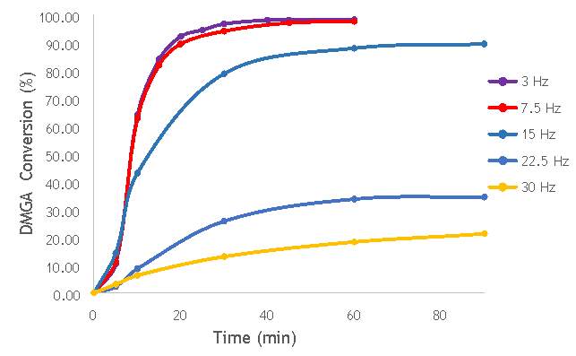
Figure 6.5: A graph showing the conversion of 2,2-dimethlyglutaric acid against time for five catalysts synthesised at five different milling frequencies in zirconia.
As shown in Figure 6.5, there is a distinct trend of catalytic activity decreasing with each increase in milling frequency. The catalysts synthesised by milling at the two lowest frequencies (3 Hz and 7.5 Hz) show the highest conversion of 2,2-dimethlyglutaric acid (DMGA) and reach peak conversion of almost 100% after only 40 minutes of reaction time. On the other hand, the catalysts synthesised at the two highest frequencies (22.5 Hz and 30 Hz) are unable to reach even 35% conversion of DMGA after 90 minutes of reaction time. As expected, this mirrors the information gathered from completing the same catalytic tests with the catalysts produced in stainless steel milling media.
As investigated previously, the high activity observed in the low frequency prepared catalysts (catalysts AgOX/TiO2(3Hz, 1bb, Zr) and AgOX/TiO2(7.5Hz, 1bb, Zr)) does not necessarily indicate the most appropriate catalyst for use in fluorination reactions. It is very likely that the high activities observed are due to a significant homogeneous contribution to the reaction by leaching of silver, as was observed in the investigation with stainless steel. In order to confirm this, further hot filtration experiments with the zirconia catalysts will need to be completed. This would allow a quantitative determination of the extent of the homogeneous contribution to the activity observed. However, time constraints have meant it has not been possible to perform the hot filtration experiments needed to determine the extent of a homogeneous contribution.
6.4.2. Effect of the number of ball bearings
After concluding the most appropriate milling frequency to prepare the catalyst, investigation of the other mechanochemical parameters began, using the optimal frequency determined in section 6.1 as benchmark to conduct the preparation reactions. It was decided it was next appropriate to consider the effect of the number of ball bearings used in the catalyst preparation process. This would further the investigation into the effect of impact in ball milling catalyst preparations on the overall catalyst activity, but also provide an insight into the enhanced mixing effects provided by use of multiple ball bearings on the activity of the catalyst synthesised.
To investigate these two key mechanisms of reaction that are utilised in ball milling, three catalysts were synthesised (catalysts 8-10) using either 2, 4 or 8, 10 mm stainless steel ball bearings. Using the reaction procedure outlined in section 5.3, the activity of each catalyst was measured as a function of DMGA conversion against time. The results of these experiments are shown graphically in Figure 6.6, alongside AgOX/TiO2(15Hz, 1bb, SS) to allow comparison of the catalysts with their single ball bearing counterpart.
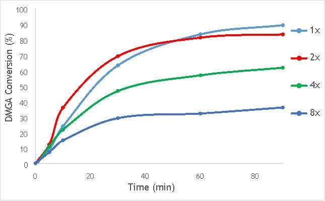
Figure 6.6: A graph showing the conversion of 2,2-dimethlyglutaric acid against time for four catalysts synthesised with differing numbers of ball bearings in stainless steel.
As shown in Figure 6.6, there is a distinct trend of catalytic activity decreasing with each increase in the number of ball bearings. Catalyst AgOX/TiO2(15Hz, 1bb, SS) shows the highest conversion of DMGA after 90 minutes, with the overall conversion decreasing as the number of ball bearings increases. AgOX/TiO2(15Hz, 8bb, SS) shows the lowest activity,only reaching 30% conversion of DMGA after 90 minutes. Interestingly, AgOX/TiO2(15Hz, 2bb, SS) shows the highest conversion until around 40 minutes of reaction time, where it reaches a plateau at 80% conversion of DMGA. It is currently unknown what causes this initially sharp rate of conversion of DMGA, and why this rate slows after only 30 minutes. A possible explanation is that the high initial rate could be due to a high homogeneous contribution to the reaction, as more homogeneous reactions tend to occur more rapidly than their heterogeneous counterparts. Unfortunately, it was not possible to test this hypothesis due to time constraints.
While this investigation indicates that increasing the number of 10mm ball bearings is detrimental to activity of the catalyst produced via milling, it does not necessarily conclude that using multiple ball bearings will lead to a lower activity catalyst than one synthesised using a single ball bearing. A similar investigation using multiple smaller ball bearings (for example 5 mm) will reduce the effect of impact on the synthetic procedure, but will allow a more thorough investigation into whether the greater degree of mixing induced by using multiple ball bearings is beneficial to catalytic activity.
6.2. Catalyst characterisation
Characterisation of the catalysts synthesised was performed to determine the speciation of the AgOX in each catalyst and to determine the morphology of the surface species. Speciation for these silver oxide catalysts can be complicated, as it can often be difficult to distinguish between the different silver species in certain characterisation methodologies. Despite this, several characterisation techniques have been used to attempt to determine the species of silver induced by different methods of mechanochemical preparation.
6.2.1. X-ray photoelectron spectroscopy (XPS)
The investigation into the speciation of the AgOX was initially undertaken using XPS techniques. XPS is a surface sensitive technique that can determine the oxidation state of the species present on the surface of catalysts. XPS was used for the speciation of several of the frequency varied catalysts that were synthesised in stainless steel milling media (catalystnumbers2, 4, 6 and 7in Table 5.2).
XPS measurements were made on a Kratos Axis Ultra-DLD XPS spectrometer, equipped with a monochromatic Al source, operating at 120 W. The binding energies were standardised against a C 1s reference line (284.7 eV) attributable to adventitious carbon. Peaks were fitted using CasaXPSTM v2.3.18. The spectra of catalyst AgOX/TiO2(22.5Hz, 1bb, SS) is shown in Figure 6.7 below, with peaks labelled according to the corresponding element. Complete spectra of all materials are shown in Appendix A.
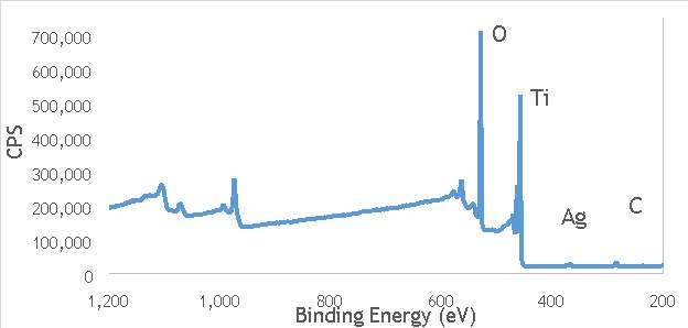
Figure 6.7: XPS spectra of AgOX/TiO2(22.5Hz, 1bb, SS) with peaks corresponding to elements labelled.
Due to the high concentration of titania compared to silver in the catalytic sample, the auger parameters are unfortunately obscured by high titania intensity. Auger parameters may have potentially led to a simpler determination of the speciation of the silver present in the catalysts, as all species of silver observed in the Ag3d region have very similar binding energies.
Despite this, to determine the speciation of the silver the Ag3d region of each catalyst was compared with that of silver(I) oxide and silver(I,III) oxide. This is shown in Figure 4.8. Note: the XPS spectrum of catalyst AgOX/TiO2(7.5Hz, 1bb, SS) is absent from Figure 6.8 as there are not any peaks observed at the Ag3d region.
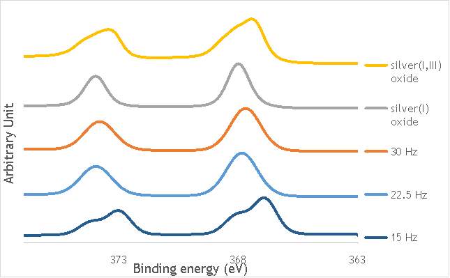
Figure 6.8: XPS Ag3d spectra of catalysts AgOX/TiO2(15Hz, 1bb, SS)AgOX/TiO2(22.5Hz, 1bb, SS) and AgOX/TiO2(30Hz, 1bb, SS), along with silver(I) oxide and silver(I,III) oxide.
As shown in Figure 6.8, all three catalysts and both the silver oxide species have very similar binding energies, making clear identification of the species present in each catalyst very difficult. However, information can be gathered to speculate on the species of silver present due to the distinct shape of the spectra obtained for each catalyst. catalyst Ag/TiO2(15Hz, 1bb, SS) has a very peculiar shape, due to the enveloping peak line being built of two distinct silver peaks. This shape is very similar to that of the silver(I,III) oxide spectrum, and so this may indicate the presence of both silver(I) and silver(III) in catalyst Ag/TiO2(15Hz, 1bb, SS). In both Ag/TiO2(22.5Hz, 1bb, SS) and Ag/TiO2(30Hz, 1bb, SS) however, much simpler peak shapes are observed indicating a single species of silver present. The shape observed is very similar to that of the silver(I) oxide peak, and so could indicate only silver(I) is present in the catalysts that have undergone higher frequency milling. This could therefore suggest that silver(III) is induced by milling and so is present in the catalysts synthesised at lower frequencies, but increasing the frequency of the milling process increases the impact exerted on the materials and leads to decomposition of silver(III). This information on speciation will have to be verified by characterisation of the materials with TPR and XRD before a conclusive outcome can be reached.
6.2.2 Temperature programmed reduction (TPR)
To obtain clearer and more distinct data on the speciation of the silver present in the catalysts synthesised, it was decided to utilise methods of TPR. TPR would allow identification of each silver(I) oxide and silver (I,III) oxide species present in each catalyst due to each reduced species showing a peak in intensity.
TPR was carried out using a Thermo TPRO 1100 instrument. The samples were fed with 10% H2/Ar at 20 ml min-1and the temperature was raised to 550 °C at a rate of 5°C min-1. The samples were each weighed to be 0.100 g and were pre-treated in argon for 60 minutes at 120°C. The TPR profiles gathered are shown in Figure 6.9 below.
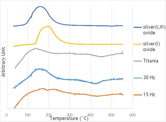
Figure 6.9: Temperature-programmed reduction profiles for catalysts AgOX/TiO2(15Hz, 1bb, SS) and AgOX/TiO2(30Hz, 1bb, SS), and titania, silver(i) oxide and silver(I,III) oxide.
In the graph shown above, five temperature-programmed reduction profiles are outlined to compare the catalysts synthesised by milling with the components that the reduction profiles may correspond to. From the data compiled, the catalyst AgOX/TiO2(15Hz, 1bb, SS) clearly shows two peaks in intensity at 170 °C and 220 °C, whereas AgOX/TiO2(30Hz, 1bb, SS) only shows a single peak at around 170 °C. The peaks in the thermograms of both AgOX/TiO2(15Hz, 1bb, SS) and AgOX/TiO2(30Hz, 1bb, SS) at 170 °C seems to correspond to the peak in the thermogram of Ag(I,III) oxide at around 160 °C, characteristic of the reduction of silver(III) to silver (I). The other peak seen in catalyst AgOX/TiO2(15Hz, 1bb, SS) at 220 °C seems to correspond to the peak shown in the thermogram of silver(I) oxide, characteristic of the reduction of silver(I) to silver(0). The peak in silver(I) oxide is slightly offset from the peak seen at 220 °C in AgOX/TiO2(15Hz, 1bb, SS), which may be due to the silver(I) in AgOX/TiO2(15Hz, 1bb, SS) being supported on titania.
This data seems to indicate that while AgOX/TiO2(15Hz, 1bb, SS) contains both silver(I) and silver(III) species, AgOX/TiO2(30Hz, 1bb, SS) contains only silver(III) species with no silver(I) species observed to have been reduced during the TPR characterisation of that catalyst. While TPR experiments on additional catalysts in the variable frequency series would have to be conducted to confirm this, this suggests that increasing the frequency of the grinding in the preparation of the catalyst, leads to a decrease in the presence of silver(I) species, but an increase in silver(III) species present. Following this, the lower kinetic activity seen in AgOX/TiO2(30Hz, 1bb, SS) compared to AgOX/TiO2(15Hz, 1bb, SS) may be due to the absence, or very low concentration, of silver(I).
The information gathered from the TPR analysis contrasts the information that the XPS experiments provided, which indicated that only silver(I) species are present in AgOX/TiO2(30Hz, 1bb, SS). Because of this, additional analysis to confirm the trend in silver species as the frequency of the ball milling used to synthesise the catalyst increases was conducted with XRD.
6.2.3. X-ray diffraction (XRD)
In order to further investigate the silver species present in the catalysts, XRD techniques were utilised. XRD analysis allows identification of all materials that have a crystalline element. This means, if silver(I) oxide and silver(I,III) oxide are present in any of the catalysts synthesised, then a peak characteristic of the oxide will be observed on the diffractogram obtained.
XRD was performed on an X’PertPRO PANalytical instrument with a Cu Kα radiation source (40kV and 40mA). Patterns were obtained at angles between 0-80°. The diffraction pattern of catalyst AgOX/TiO2(15Hz, 1bb, SS) is shown in Figure 6.10 along with all compounds that are potentially responsible for the peaks observed. Complete data of all diffraction patterns obtained are shown in Appendices B and C.
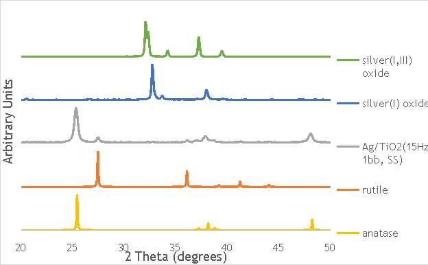
Figure 6.10: Diffractogram of catalyst AgOX/TiO2(15Hz, 1bb, SS) along with anatase and rutile (two allotropes of TiO2) and silver(I) oxide and silver(I,III) oxide (two possible speciations of AgOX in the catalyst)
In Figure 6.10, the diffraction pattern of catalyst AgOX/TiO2(15Hz, 1bb, SS) is shown along with diffraction patterns of all chemicals that may be responsible for the reflection peaks shown. This figure includes theoretical patterns of anatase and rutile (the two allotropes of TiO2 found in Titanium(IV) oxide, AeroxideTM P25), as well as measured patterns of both silver(I) oxide and silver(I,III) oxide.
Whilst throughout the measurement of AgOX/TiO2(15Hz, 1bb, SS) species of titania are evident, there are not any visible reflections of silver(I) oxide or silver (I,III) oxide. This is due to the silver only occupying 1% of the sample by mass. Magnification of the patterns between 30° and 35° (the area of the highest intensity of both silver species) allows identification of the oxide species present. In order to identify the species of silver present in each catalyst in the frequency altered series, a pattern containing the catalysts numbered 2-6 in Table 5.2between angles 30 and 35° is shown in Figure 6.11 below. The catalysts AgOX/TiO2(3Hz, 1bb, SS) and AgOX/TiO2(30Hz, 1bb, SS) have been omitted due to the peaks and background not being fully resolvable.
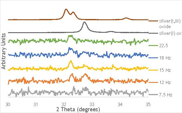
Figure 6.11: diffraction patterns of several catalysts in the frequency-varied in stainless steel series (catalyst numbers 2-6) as well as silver(I) oxide and silver(I,III) oxide between 30 and 35°.
As shown in the diffraction patterns, the catalysts synthesised at the lowest frequencies show peaks characteristic of both silver(I) oxide and silver(I,III) oxide. As you increase the frequency that the catalysts are synthesised, the silver(I) oxide disappears while the peak characteristic of silver(I,III) oxide becomes more intense. The intensity of the silver(I,III) oxide and silver(I) oxide peaks seems to be relatively equal, until the frequency increases to 15 Hz where the silver(I,III) oxide peak surpasses that of silver(I) oxide.
The data shown clearly supports the information obtained from TPR, which showed peaks corresponding to the reduction of silver(I) oxide and silver(III) oxide for catalyst AgOX/TiO2(15Hz, 1bb, SS), but only a single peak corresponding to silver(III) oxide in catalyst AgOX/TiO2(30Hz, 1bb, SS).
In order to determine how the silver species present are effected by increasing the number of ball bearings used in the synthesis of the catalysts, diffractograms of catalysts AgOX/TiO2(15Hz, 2bb, SS), AgOX/TiO2(15Hz, 4bb, SS) and AgOX/TiO2(15Hz, 8bb, SS) were obtained. Diffraction patterns of these catalysts and catalyst AgOX/TiO2(15Hz, 1bb, SS) between angles 30 and 35° is shown in Figure 6.12 below, along with patterns for silver(I) oxide and silver(I,III) oxide.
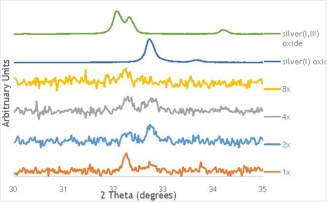
Figure 6.12: diffraction patterns of catalystsAgOX/TiO2(15Hz, 1bb, SS), AgOX/TiO2(15Hz, 2bb, SS), AgOX/TiO2(15Hz, 4bb, SS) and AgOX/TiO2(15Hz, 8bb, SS), as well as silver(I) oxide and silver(I,III) oxide, between angles of 30 and 35°.
As shown in the diffraction patterns, increasing the number of ball bearings seems to lead to an increase in the intensity of the silver(I) oxide peak. Both catalysts AgOX/TiO2(15Hz, 2bb, SS) and AgOX/TiO2(15Hz, 4bb, SS) show a more intense peak at 32.8°, the angle corresponding to a silver(I) oxide peak, than AgOX/TiO2(15Hz, 1bb, SS). However, this peak isn’t seen after increasing the number of ball bearings used for the catalyst synthesis to 8. This also leads to a shorter and broader silver(I,III) oxide peak.
As it is currently unknown what causes the formation of silver(I,III) oxide, it is difficult to speculate as to the reasons why an increase in the number of ball bearings used in the synthetic process from one to two leads to a more intense silver(I) oxide peak observed. One possible explanation is that this could be due to the enhanced mixing effects caused by using additional ball bearings.
The XRD also shows that increasing the number of ball bearings, or increasing the frequency that the ball milling takes place at, appears to cause the materials to become more amorphous. The catalysts synthesised with more ball bearings show diffraction patterns noticeably smaller and broader than those synthesised with a single ball bearing. This effect is mirrored in the frequency-altered series, where peaks can be seen to be broader and shorter in the diffraction patterns of the catalysts synthesised at higher frequencies. This correlation may be attributed to the more intense force caused by milling at high frequencies or with multiple ball bearings. Possible reasons for this are that the more intense milling may generate smaller particles, or potentially cause the crystallinity of the titania to fall, or a combination of the two.
The data gathered from use of TPR and XRD clearly indicate that silver(I) oxide is present in the catalysts that are synthesised at the lower/middle frequencies, but at higher frequencies silver(I,III) oxide dominates. This information can therefore be indicative of the trend in activity of the catalysts synthesised as the frequency of the ball milling increases.As determined mechanistically by Flowers’ II and Zhang for radical decarboxylative fluorination reactions using SELECTFLUOR® (shown in Figures 3.4 and 3.5), silver(I) is the catalytic species of silver involved in the cycle. If the heterogeneous reaction process follows the same catalytic mechanism, then any catalyst synthesised that contains only low amounts of silver(I) species will not be very active for this reaction.
The information from TPR and XRD contrasts the information that the XPS experiments provided, which indicated that only silver(I) species exist in AgOX/TiO2(30Hz, 1bb, SS).However, the kinetic and mechanistic information points towards silver(III) being catalytically inactive for the decarboxylative fluorination reactions. Due to the low kinetic activity of AgOX/TiO2(30Hz, 1bb, SS) it is very likely the information indicated by XPS is not completely accurate, and the information provided by TPR and XRD indicating silver(III) to be the dominant species in AgOX/TiO2(30Hz, 1bb, SS) is much more likely. A reason for the possible inaccuracy of the data gathered from XPS is due to XPS being a surface sensitive technique. This means that this technique is not nearly as sensitive to the bulk as TPR and XRD, and so could be providing inaccurate identifications of the species present in each catalyst.
In order to conclusively determine if the silver(I) oxide content of each catalyst is the defining factor of its activity, more characterisation will have to be completed to ascertain the other factors that could cause the catalytic activity trend observed, such as particle size and surface area.
6.2.4. N2 Physisorption
To continue the characterisation of the mechanochemically synthesised AgOX catalysts, N2 physisorption analysis was completed to produce data on the surface area of the materials. Information on surface area would provide an opportunity to investigate whether the reduction in crystallinity as the milling frequency increases is due to smaller particles being formed, or the framework becoming more amorphous. It could also indicate further reasons for the catalytic activity trend observed as the milling frequency used for the synthesis of the catalysts is increased.
To measure the surface area of the catalysts using N2 physisorption, a sample of around 0.1 g was evacuated for 2hours at -196 °C using a Quantachrome Quadrasorb SI instrument. The surface area analysis was performed at 120 °C and surface areas were calculated using BET theory over the range P/P0 = 0-1.
Surface area analysis was performed on the catalysts AgOX/TiO2(7.5Hz, 1bb, SS), AgOX/TiO2(15Hz, 1bb, SS) and AgOX/TiO2(30Hz, 1bb, SS), in order to achieve an understanding of the impact of the milling frequency on the overall surface area of the resultant catalysts synthesised. The results of these measurements are shown below:
Ag/TiO2(7.5Hz, 1bb, SS): 11.6553 m2 g-1
Ag/TiO2(15Hz, 1bb, SS): 23.1909 m2 g-1
Ag/TiO2(30Hz, 1bb, SS): 47.8575 m2 g-1
This trend shows that on increasing the frequency used to produce the catalyst, the overall surface area of the catalyst also increases. This suggests that the higher degree of impact exerted on the materials from increasing the frequency of the milling process leads to smaller particles produced, and hence a larger surface area achieved. As it has been observed that the activity of the catalyst decreases as the frequency used to produce the catalyst is increased, this also suggests that the surface area of the catalyst does not have a substantial effect on the overall activity of the catalyst.
While an increase in the particle size of the catalyst would explain the broader peaks observed in the diffraction patterns as the milling frequency increases, the BET measurements do not provide data that conclusively explains that this is the case. Analysis of the surface area of all the catalysts in the frequency-altered series would need to be performed to determine if the trend is followed, and additional measurements to confirm the particle size of the catalysts would need to be conducted.
6.2.5. Scanning electron microscopy (SEM)
To obtain data on the particle size, surface topography, elemental composition and elemental distribution of the mechanochemically synthesised AgOX/TiO2 catalysts, SEM-EDX analysis was performed. This information allows qualitative and quantitative information to be gathered, through the comparison of surface images and elemental analysis of materials. SEM-EDX was carried out for both catalysts AgOX/TiO2(15Hz, 1bb, SS) and AgOX/TiO2(30Hz, 1bb, SS) to obtain a comparison of the characterisation of the catalysts as milling is increased.
SEM-EDX was performed using a Hitachi TM3030Plus Tabletop Microscope equipped with an Energy Dispersive X-ray Spectrometer Quantax70. SEM images were gathered at 2000x magnification with a 15 kV electron beam. These images are shown in Figure 6.13 below:
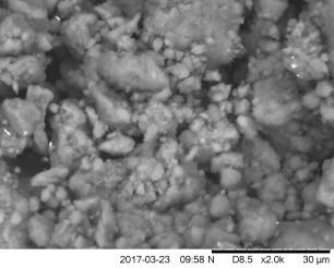
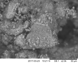
Figure 6.13: Micrograph of AgOX (15Hz, 1bb, SS) (left) and AgOX (30Hz, 1bb, SS) (right), processed by SEM.
Figure 6.13 shows the difference in the particle sizes of the two catalysts. As can be seen in the above images, AgOX/TiO2(30Hz, 1bb, SS) shows much larger agglomerates of silver particles than AgOX/TiO2(15Hz, 1bb, SS). This agglomeration is apparent due to the huge size of the structures observed in right image. This agglomeration is also seen in the images of the silver distribution, generated by EDX. This is shown in Figure 6.14 below:
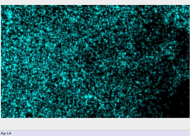
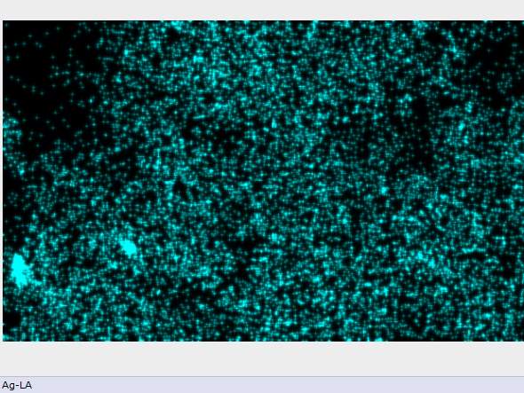
Figure 6.14: Distribution of silver in AgOX/TiO2(15Hz, 1bb, SS) and AgOX/TiO2(30Hz, 1bb, SS) (right), processed by EDX.
In the images shown above, the large agglomerates observed in the SEM images of AgOX/TiO2(30Hz, 1bb, SS) are evident in the intensely radiating clusters of silver shown in the right image in Figure 6.14 above. While there are still clusters of silver particles visible in the image of AgOX/TiO2(15Hz, 1bb, SS) they are much smaller and the overall distribution of silver across the surface seems to be greater.
The information gathered from the SEM-EDX analysis indicates that increasing the frequency of the milled AgOX catalyst preparation may lead to larger agglomerates of surface silver forming. The above images show larger particles of silver in Figure 6.13 and larger clusters of silver in Figure 6.14 in AgOX/TiO2(30Hz, 1bb, SS) compared to AgOX/TiO2(15Hz, 1bb, SS). While SEM-EDX analysis would have to be performed on other catalysts prepared in stainless steel in the variable frequency series to confirm this, the higher frequency of milling used in producing AgOX/TiO2(30Hz, 1bb, SS) could be responsible for the large agglomerates seen. This may also explain the lower activity exhibited by AgOX/TiO2(30Hz, 1bb, SS) compared to AgOX/TiO2(15Hz, 1bb, SS) for radical decarboxylative fluorination with DMGA, as larger particles can lead to a less active catalytic surface.
While these methods of characterisation and speciation of the frequency-altered AgOX/TiO2 catalysts (catalystsnumbers1-7 in Table 5.2) produced using mechanochemistry provide an interesting and stimulating insight into the behaviour of the catalysts under a certain milling parameter, this is far from a conclusive outlook. Characterisation and comparison of the number of active sites on the surface of each of the frequency-altered catalysts through CO pulse titration would have allowed a deeper understanding of the activity profiles obtained, however time constraints have meant this has not been possible. It would also have been beneficial to synthesise catalysts at a larger range of frequencies to further narrow the parameters that lead to a highly active and highly stable catalyst. Both these aspects will produce highly interesting and informative data when completed.
As well as the work specific to the varying of frequency, the mechanochemical parameters still need to be fully optimised and more kinetic data will have to be gathered on all variations of milling media, number of ball bearings and ball bearing size. Experiments more specific to the materials used in the catalyst will also have to be performed to optimise the catalyst in the form of support material and silver loading. To determine the generality of the catalysts in terms of carboxylic acids, a range of substrates will need to be investigated for activity and selectivity, including primary secondary and tertiary carboxylic acids.
7. Conclusion
In this thesis, the viability of mechanochemistry as a means for active AgOX/TiO2 catalyst production has been explored. Mechanochemistry has been demonstrated to be a capable method of preparing highly active catalysts that allow near-complete conversion of a carboxylic acid to a fluorinated product in rapid timeframes. The stability of some of these catalysts have been verified, with a combination of high stability and activity demonstrated to be achievable through methods of ball milling. In addition, a variety of characterisation techniques have been utilised to conclusively determine the speciation of the silver in the catalysts, as well as obtain information on the surface characteristics of the material.
Through the experiments conducted, it has been determined that milling at 15 Hz with 1 ball bearing is most suitable for producing a catalyst with an effective compromise between activity and stability. The catalyst AgOX/TiO2(15Hz, 1bb, SS) demonstrated high activity with only a low homogeneous contribution to the reaction. In addition, it was demonstrated that the catalysts produced were equally effective whether they were produced in the milling materials of stainless steel or zirconia.
The characterisation techniques employed allowed identification of the species of silver present in each of the catalysts synthesised. This allowed a trend to be observed between each of the catalysts in the frequency-varied series. An increase in frequency resulted in a decrease in the presence of silver(I) oxide and an increase in the presence of silver(I,III) oxide. This characterisation clearly links the kinetic data on catalyst activity with the mechanistic proposals by Flowers II et al. and Zhang. Preliminary information was also gathered on the effect of frequency on the surface structure of the catalysts synthesised.
While the information collected provides a solid foundation for continued investigation into the effects of mechanochemical parameters on the kinetics and characteristics of silver-catalysts, it is by no means conclusive. A number of thesis targets previously outlined will still need to be investigated, and further characterisation, such as CO pulse titration, will need to be conducted to complete the research presented.
Overall, this thesis has provided a valuable insight into the effect of several mechanochemical parameters on the characteristics of the resultant AgOX/TiO2 catalyst, and provided a firm benchmark for further investigation.
Appendices
Appendix A: XPS spectra of catalysts2, 4, 6 and 7 along with silver(I) oxide and silver(I,III) oxide
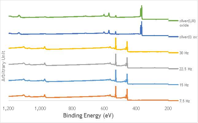
Appendix B: Diffraction patterns of catalysts 1-7
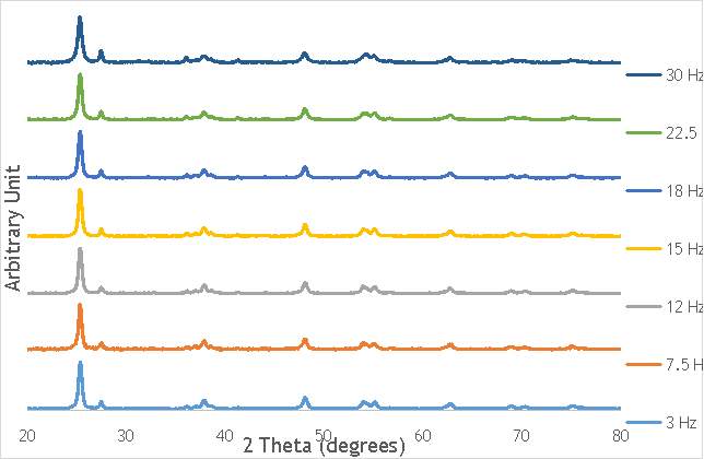
Appendix C: Diffraction patterns of catalysts4 and 8-10 along with silver(I) oxide and silver(I,III) oxide
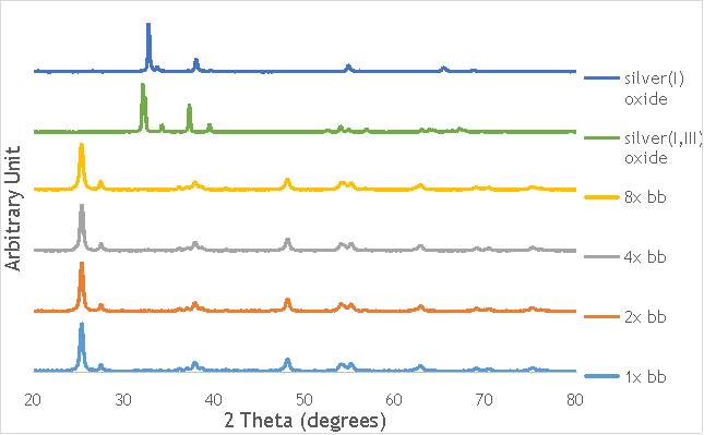
[1] C. Heidelberger, Nature, 1957, 179, 663-666.
[2] D. O’Hagan, Chem. Soc. Rev., 2008, 37, 308-319.
[3] D. Harper and D. O’Hagan, Nat. Prod. Rep., 1994, 11, 123.
[4] M. Shimizu and T. Hiyama, Ange. Chem. Int. Ed., 2005, 44, 214-231.
[5] X. Xu, J. Org. Chem., 2016, 81, 6887-6892.
[6] L. Radulovic and Z. Wojcinski, Encyclopedia of Toxicology, 2014, 1133-1136.
[7] M. Pagliaro and R. Ciriminna, J. Mater. Chem., 2005, 15, 4981.
[8] B. Ameduri and B. Boutevin, J. Fluorine Chem., 2000, 104, 53-62.
[9] M. Dubecký, J. Phys. Chem. Lett., 2015, 6, 1430-1434.
[10] P. Miller, N. Long, R. Vilar and A. Gee, Ange. Chem. Int. Ed., 2008, 47, 8998-9033.
[11] S. Purser, P. Moore, S. Swallow and V. Gouverneur, Chem. Soc. Rev., 2008, 37, 320-330.
[12] W. Middleton, J. Org. Chem., 1975, 40, 574-578.
[13] W. Middleton and E. Bingham, J. Org. Chem., 1980, 45, 2883-2887.
[14] G. Posner and S. Haines, Tetrahedron Lett., 1985, 26, 5-8.
[15] A. Boukerb, D. Grée, M. Laabassi and R. Grée, J. Fluorine Chem., 1998, 88, 23-27.
[16] F. Beaulieu, L. Beauregard, G. Courchesne, M. Couturier, A. L’Heureux, Org. Lett., 2009, 11, 5050-5053.
[17] M. Pouliot, L. Angers, J. Hamel and J. Paquin, Tetrahedron Lett., 2012, 53, 4121-4123.
[18] D. Lu, G. Liu, C. Zhu, B. Yuan and H. Xu, Org. Lett., 2014, 16, 2912-2915.
[19] A. Orliac, D. Gomez Pardo, A. Bombrun and J. Cossy, Org. Lett. 2013, 15, 902-905.
[20] R. Banks, N. Lawrence and A. Popplewell, Chem. Commun., 1994, 343-344.
[21] E. Differding and H. Ofner, Synlett, 1991, 187-189.
[22] P. Nyffeler, S. Durón, M. Burkart, S. Vincent and C. Wong, Ange. Chem. Int. Ed., 2004, 44, 192-212.
[23] V. Rauniyar, A. Lackner, G. Hamilton and F. Toste, Science, 2011, 334, 1681-1684.
[24] G. S. Lal, J. Org. Chem., 1993, 58, 2791–2796
[25] M. Zupan, J. Iskra and S. Stavber, J. Fluorine Chem., 1995, 70, 7-8.
[26] W. Peng and J. M. Shreeve, J. Org. Chem., 2005, 70, 5760–5763
[27] V. Rauniyar, A. Lackner, G. Hamilton and F. Toste, Science, 2011, 334, 1681-1684.
[28] J. Hutchinson and G. Sandford, Top. Curr. Chem., 1997, 1-43.
[29] A. Lothian and C. Ramsden, Synlett, 1993, 753-755.
[30] V. Grakauskas, J. Org. Chem., 1969, 34, 2446-2450.
[31] T. Patrick, K. Johri and D. White, J. Org. Chem., 1983, 48, 4158-4159.
[32] C. Ramsden and M. Shaw, Tetrahedron Lett., 2009, 50, 3321
[33] M. Rueda-Becerril, C. Chatalova Sazepin, J. Paquin and G. Sammis, J. Am. Chem. Soc., 2012, 134, 4026-4029.
[34] F. Yin, Z. Wang, Z. Li and C. Li, J. Am. Chem. Soc., 2012, 134, 10401-10404.
[35] N. Patel and R. Flowers II, J. Org. Chem., 2015, 80, 5834-5841.
[36] X. Zhang, Comp. Theor. Chem, 2016, 1082, 11-20.
[37] J. Bravo-Suárez, R. Chaudhari and B. Subramaniam, ACS Symp. Ser., 2013, 3-68.
[38] G. Hutchings, R. Catlow, M. Davidson and N. Turner, Modern developments in catalysis, World Scientific, 1st edn., 2016.
[39] A. Villa, D. Wang, G. Veith, F. Vindigni and L. Prati, Catal. Sci. Technol., 2013, 3, 3036.
[40] I. Gandarias, E. Nowicka, B. May, S. Alghareed, R. Armstrong, P. Miedziak and S. Taylor, Catal. Sci. Technol., 2016, 6, 4201-4209.
[41] N. Dimitratos, J. Lopez-Sanchez, D. Morgan, A. Carley, R. Tiruvalam, C. Kiely, D. Bethell and G. Hutchings, Phys. Chem. Chem. Phys., 2009, 11, 5142.
[42] S. James, C. Adams, C. Bolm, D. Braga, P. Collier, T. Friščić, F. Grepioni, K. Harris, G. Hyett, W. Jones, A. Krebs, J. Mack, L. Maini, A. Orpen, I. Parkin, W. Shearouse, J. Steed and D. Waddell, Chem. Soc. Rev., 2012, 41, 413-447.
[43] K. Ralphs, C. Hardacre and S. James, Chem. Soc. Rev., 2013, 42, 7701.
[44] L. Leite, V. Stonkus, K. Edolfa, L. Ilieva, L. Plyasova and V. Zaikovskii, Appl. Catal. A., 2006, 311, 86-93.
[45] U. Kamolphop, S. Taylor, J. Breen, R. Burch, J. Delgado, S. Chansai, C. Hardacre, S. Hengrasmee and S. James, ACS Catal., 2011, 1, 1257-1262.
[46] V. Boldyrev, Rus. Chem. Rev., 2006, 75, 177-189.
[47] R. Sheldon, Green Chem., 2005, 7, 267.
[48] S. James, T. Friščić and K. Harris, Chem. Soc. Rev., 2012, 41, 413-447.
[49] Retsch.com, 2017
[50] G. Štefanić, S. Krehula and I. Štefanić, Chem. Commun., 2013, 49, 9245.
[51] I. CHORKENDORFF and J. NIEMANTSVERDRIET, CONCEPTS OF MODERN CATALYSIS AND KINETICS, WILEY VCH, [S.l.], 1st edn., 2017.
[52] D. Morgan, 2017.
Cite This Work
To export a reference to this article please select a referencing stye below:
Related Services
View all


Related Content
All TagsContent relating to: "Chemistry"
Chemistry is a science involving the study of the elements and matter at the atomic and molecular level including their composition, structure, properties, behaviour, and how they react or combine.
Related Articles

DMCA / Removal Request
If you are the original writer of this dissertation and no longer wish to have your work published on the UKDiss.com website then please: