Maintenance Optimisation of EMU Rolling Stock Assets using RCM
Info: 23643 words (95 pages) Dissertation
Published: 11th Dec 2019
Tagged: Business
| Table of Contents | Page |
List of tables
List of figures
Abbreviations
Abstract
Declaration
Copyright statement
Achknoledgements
1 Chapter One – Introduction
1.1 Rolling Stock
1.2 UK Rolling Stock Market
2 Scope and Objectives
3 Chapter Two – Literature review
3.1 Diesel multiple Unit (DMU)
3.2 Electrical Multiple Unit or EMU
3.3 Component function and operation of an EMU
3.4 Electric motor
3.5 Motor control system
3.6 Power converters
3.7 Electronic controller
3.8 Energy source – batteries
3.9 Reliability block diagram
4 Chapter Three – Methodology
4.1 Reliability Centred Maintenance
4.2 Fundamental concept of RCM method
4.3 FMECA vs. COFA
4.4 Labelling of asset component
5 Chapter Four – Results and findings
5.1 Components classification and effects of failures
5.2 Key component findings
5.3 Discussion
5.4 Chapter conclusions
6 Chapter five – Conclusion and future development
7 References
Appendix A COFA worksheet for Electrical Multiple Unit
Appendix B PM task work sheet for Electrical Multiple Unit
List of tables
Table 1: Comparison of an EV and an ICEV over the Vehicle Life
Table 2: UK rolling stock MTIN details by fleet type
Table 3: Evaluation of different EMU motors
Table 4: Long term performance goals for batteries as set out by USABC
Table 5: Status of batteries performances for automotive applications
Table 6: COFA worksheet sample
Table 7: PM Task Selection sheet sample
Table 8: Component Labelling Sample
Table 9: Li-Ion Battery Pack safety system detection and prevention
Table 10: failure cause and PM tasks
Table 11: failure causes and PM tasks
Table 12: failure causes and PM tasks for PMSM
Table 13: Failure Causes of each component in electric motor
Table 14: PM task and failure causes for inverter
Table 15: PM task and failure causes for circuit breaker
Table 16: Failure cause and PM task for temperature sensor
List of figures
Figure 1: represents a schematic drive train of a typical DMU vehicle.
Figure 2: Typical electric multiple unit configurations
Figure 3: General EMU configuration block diagram
Figure 4: EMU drive train configuration
Figure 5: Different EMU configuration
Figure 6: Single motor configuration Figure 7: Multiple motor configurations
Figure 8: a) Mechanical differential gearing (left) b: Electrical differential gearing (right)
Figure 9:In wheel drive configuration
Figure 10: Block diagram for an EMU and technical description
Figure 11: different types of electric motors and their configuration
Figure 12: DC motor operation illustration; b: field and armature control of the motor
Figure 13: Operational principle of an Induction Motor
Figure 14: torque and speed control of the PM brushless motor
Figure 15: DC/AC three-phase Voltage-fed inverter
Figure 16: Digital signal processor – block diagram
Figure 18: EMU key component Reliability Block Diagram
Figure 19: Typical EMU configuration, Illustration of control, electric and mechanical links
Figure 21: PM task selection Logic tree
Figure 23: Component criticality classifications
Figure 24: Consequences of failures, according to the ARC
Figure 25: failure percentage of each component in PMSM motor
Abbreviations
AC Alternating Current
DC Direct Current
DMU Diesel Multiple Unit
EMU Electric Multiple Unit
IC Internal Combustion
EV Electric Vehicle
PdM Predictive Maintenance
PM Preventive maintenance
CM Corrective Maintenance
EV Pure-Electric Vehicle
FCEV Fuel-Cell Electric Vehicles
HEV Hybrid Electric Vehicles
PHEV Plug-In Hybrid Electric Vehicles
ICEV Internal Combustion Engines vehicle
Li-Ion Lithium-ion
Ni-Cd Nickel-Cadmium
Ni-MH Nickel-Metal Hydride
PMSM Permanent Magnet Synchronous Motor
PMBM Permanent Magnet Brushless Motor
DSP Digital Signal Processor
OEM Original Equipment Manufacturers
RCM Reliability centered Maintenance
RBD Reliability Block Diagram
FMECA Failure Mode, Effects and Criticality Analysis
COFA Consequence of Failure Analysis
RTF Run-to-failure component
ARC Asset Reliability Criteria
MTIN Miles per Technical incident
Abstract
With increasing population worldwide and increasing demand of public transport, one of the greatest challenges for every government is to reduce air pollution levels not just for their country but globally. With advancing technology and increasing demand for public transport there is more emphasis on producing less CO2 emissions. The use of electric vehicle for transporting passengers and goods could ensure reduction in emission with a more environmental friendly option.
This thesis work intends to focus on reliability and maintainability of Electrical Multiple Units (EMUs) as they are becoming more desirable in the UK as well as around the world for transporting people as well as goods.
The main objectives of this paper are:
- To conduct research into EMU (Electric Multiple Unit) technology, describing functions and operations of its various components like mechanical, electrical and electronics.
- To identify and define a long term maintenance plan for modern EMUs based on RCM methodology.
RCM methodology has been selected and applied to the EMU rolling stock for its systems, design and completing worksheets (COFA worksheet and PM task worksheet). This will form the suggested maintenance plan. This proposed plan consists of various elements including, failure modes identification, failure effects on the vehicle, criticality classification of the components, failure causes identification and suggested preventive maintenance tasks with appropriate periodicity.
1 Chapter One – Introduction
One of the main causes for air pollution around the world is use of automobile running on fossil fuels with ever so expanding conventional automotive industry. In a bid to improve the effects on automobiles there have been a number of developments in recent years to reduce the emissions from automobiles. Governments in different countries across the world are investing in more efficient and environment friendly public transport systems with qualities like high efficiency, reduction of emission, and use of unconventional energy sources.
Some of the main advantages of using electric vehicles for transportations are highlighted below; even though production of electricity is still mostly supplied by fossil fuels.
- The power plants are usually located far from cities and urban centres;
- The efficiency of power plants are higher than transportation vehicles, which is a base condition to save energy sources; and
- Power plants are equipped with systems for the reduction of pollution which are more effective than on the ones on vehicles.
In a bid to improve the effects on automobiles there have been a number of developments in recent years to reduce the emissions from automobiles. Governments in different countries across the world are investing in more efficient and environment friendly public transport systems. Around the world trains are considered as the most economical and efficient way to travel. In the UK we have seen a large investment in electric trains commonly known as Electric Multiple Unit or EMUs.
Electric vehicles have zero emissions at the point of use and it’s called ‘tank-to-wheel’ concept, when powered solely by the battery or electric current. The ‘well-to-wheel’ concept includes the CO2 emissions during electricity generation, which depends on the current mixture of fuels used to make the electricity for the grid. To correctly compare the emissions from all type of vehicles, one has to use the ‘well to wheel’ concept, which includes the CO2 emissions during production, refining and distribution of petrol/diesel.
On a comparable basis taking into account both electricity generations, the processes necessary to deliver fuel to the vehicle, emission factors and lifetime carbon use have been calculated for vehicles manufactured in 2010, 2020 and 2030. For ICEVs, the addition of pre-combustion emissions (extraction, refining, transport, etc.) typically adds another 10-18% to the ‘tank to wheel’ figure. The table below presents these ‘well to wheel’ figures.
| Vehicle manufactured in 2010 | ||||
| Typical EV | ICEV | |||
| GaBi 4 factors grid mix * | Petrol | Diesel | ||
| Emission factor | 106 | 172 | 156 | |
| well to wheel gCO2/km | ||||
| Lifetime vehicle carbon | ||||
| use | 19,161 | 30,916 | 28,012 | |
| kg CO2 – equiv | ||||
| Vehicle manufactured in 2020 | ||||
| Emission factor | 56 | 144 | 130 | |
| well to wheel gCO2/km | ||||
| Lifetime vehicle carbon | ||||
| use | 10,132 | 25,864 | 23,435 | |
| kg CO2 – equiv | ||||
| Vehicle manufactured in 2030 | ||||
| Emission factor | 41 | 120 | 109 | |
| well to wheel gCO2/km | ||||
| Lifetime vehicle carbon | ||||
| use | 7,390 | 21,639 | 19,606 | |
| kg CO2 – equiv | ||||
Table 1: Comparison of an EV and an ICEV over the Vehicle Life [4]
With improved technology and stricter measures for electricity generation to lower the carbon generation, the overall emission figure for running an electric vehicle will drop further. Currently lowest emitting ICEV produces tailpipe (tank to wheel) emissions of 86g CO2/km. Adding the average ‘well to tank’ proportion (which starts at 10% and equates to 8.6g CO2/km) means ICEVs can achieve ‘well to wheel’ emissions as low as 94.6g CO2/km and ICE vehicles are being refined to further reduce the ‘tank to wheel’ emissions.[7]
1.1 Rolling Stock
The term Rolling Stock refers to trains running on the rail guided systems (tracks) to transport goods or passengers between two locations. The railway transportation system is considered the cheapest mode of transport and is very popular globally. Rolling stock or trains are usually split into the following main categories:
- EMU (Electrical Multiple Unit)
- DMU (Diesel Multiple Unit)
- Locomotives
- Metro (Urban Mass Transport Systems)
- Light Rail (Trams)
This study has been focused on the main line railway rolling stock within the UK.
*Gabi 4is a life cycle assessment tool conforming to the ISO 14040 Life Cycle Assessment (LCA) standards. It is designed to allow the user to model the whole life cycle (or part) of a product or service and provides a quantitative output on a range of environmental impacts.
1.2 UK Rolling Stock Market
The UK mainline railway or British railway is the oldest railway in the world and has been running for almost 175 years. During this time the railway has seen a number of rolling stocks from steam engines hauling the passenger coaches (Steam Train) to the modern High speed trains running between the UK and Europe with a speed of almost 350km/h.
Since privatisation of British Rail in 1994, a number of operators are running different train franchises across the UK usually referred to as TOCs. There is a huge pressure on these TOCs and asset owners to meet increasing public demand as well as improving reliability of these assets.
During the time initial stages of privatisation the train operating companies did not focus on train reliability and passenger experiences; which saw a decline in passenger numbers using rail transport, however since 2012 there has been an increased demand of rail transport by a large number of people as well as growing UK economy.
Each train operating companies in the UK have obligations to meet targets for better performances and reliability of the trains to ensure better passenger experience as well as minimise disruptions. There are just over 12000 vehicles currently operating on the UK main line railway with predicted growth of 26% by 2024 to meet demands and replacement of old fleets. Most of the UK fleet, around 70 percent, comprises of electric vehicles and more than 50 percent of the total fleet is over 20 years old (half life of a rolling stock vehicle). Hence there is an increased demand for better maintenance practices for these assets to optimise their life and operational capabilities.
The industry standard to measure train reliability across the UK main line rail market is MTIN (Mean time per technical incident) and currently the national average for different fleet stands as follows:
| Fleet Type | MTIN |
| Old generation DMU | 7,291 |
| Midlife DMU | 9,184 |
| Modern DMU | 16,081 |
| Old generation EMU | 13,872 |
| Midlife EMU | 18,347 |
| Modern EMU | 36,859 |
| Other Intercity Traction | 15,331 |
Table 2: UK rolling stock MTIN details by fleet type [41]
2 Scope and Objectives
The purpose of this dissertation is to understand maintenance principals being used for the maintenance of different fleet within the UK and develop methodology for maintenance optimisation by using modern techniques like RCM. In order to achieve a holistic approach to the rolling stock maintenance, the dissertation aims to achieve the following objectives;
- Analysis and understanding of the typical architecture of the EMU.
- Identification of the best maintenance strategy for the EMU train system using the RCM method and definition of a long-term maintenance plan.
- To provide future asset managers an overview and insight on implementing RCM in railway market
The main objective of this thesis work is to produce a maintenance program for Electric Multiple Units or EMUs by studying different sub systems of the EMU and applying the RCN methodology.
3 Chapter Two – Literature review
The conventional trains (Rolling Stock) rely on an internal combustion engine for propulsion with petrol or diesel providing the energy. On the other hand EMUs use an electric motor for traction, chemical batteries, fuel cells, ultra capacitors and/or flywheels as energy sources. An EMU has advantage over a DMU or Loco hauled rolling stock due to its light weight as well as absence of emissions, high efficiency, flexible structure and less noise & vibration.
This chapter talks about the state of the art electric multiple units (Electric Trains) technology and their structure describing their operational and fundamental principles, the multiple drive train configurations and the typical system composition using detailed diagrams.
3.1 Diesel multiple Unit (DMU)
A Diesel Multiple Unit or DMU is a multiple unit train powered by diesel engines mounted on the vehicles and are incorporated on more than on vehicles (car). The following four main factors are very important while specify a train vehicle and its engine requirement.
- To develop sufficient power to match the requirements of the load;
- To carry sufficient energy to support vehicle driving on a target range;
- Have high efficiency; and
- Produce controlled environmental pollution.
A usual drive train consists of a power unit (engine or electric motor), a clutch in manual transmission or a torque converter in automatic transmission, a gearbox (transmission), final drive, differential, drive shaft, and wheels as illustrated in figure 1.
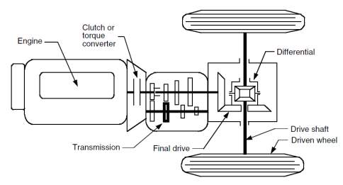
Figure 1: represents a schematic drive train of a typical DMU vehicle. [3]
In manual transmission the clutch is used to couple or decouple the gearbox from the power unit while a torque converter replaces the clutch in automatic transmission. It consists of a hydrodynamic device with a continuously variable gear ratio. The gearbox supply a few gear ratios from its input shaft to its output shaft for the power plant torque-speed profile to meet the demand of vehicle performance by incorporating both clutch and gearbox. The driver can shift the gear ratio and hence the torque going to wheels. The final drive is usually a pair of gears that reduce further the speed and distribute the torque to each wheel through the differential. Differential is a mechanical device that allows the wheels to have different speed along a curved path, where the outer wheel rotates faster than inner one. All these links between these devices are mechanical links and this is why the drive train configuration is not so flexible.
3.2 Electrical Multiple Unit or EMU
An electric multiple unit or EMU is a multiple unit train made of self powered vehicle using the electricity as the motive power. There are no diesel engines on these units and the electric motors are fitted to one of more carriages. These electric motors are the primary source of providing energy to the train. Figure 2 below shows the typical configuration of an electric multiple unit transmission.
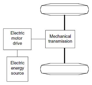
Figure 2: Typical electric multiple unit configurations [3]
In the past we have seen a number of diesel multiple units converted into EMUs; however the lower flexibility, poor performance and the heavy weight have caused the use of this type of EMUs to disappear. Instead the modern EMUs are built based on original body and frame design. This solution takes the significant advantage over the “converted” one because it provides the engineer with the flexibility to coordinate and integrate various subsystems so that they can work together efficiently in order to improve reliability.
The modern EMUs offer better flexibility based on several different factors such as energy flows in the electric train is mainly via flexible electrical wires rather than bolted flanges and rigid shafts. The torque-speed characteristic of an engine covers only a narrow range, the required performances of the vehicle have to be achieved through gear changing. On the other side, the electric vehicle propulsion design is more flexible with single or multiple electric motors, gearing (reduction or differential) axels and wheels.
The EMUs also gives the possibility to choose from different energy sources (such as batteries, Direct current (DC) and alternative current (AC) which can further affect the performance of the train.
3.2.1 Typical structure and behaviour of an EMU
A typical configuration of an EMU is shown in the figure 3 below and consists of three major subsystems:
- Electric motor propulsion;
- Energy source system;
- Auxiliary system.
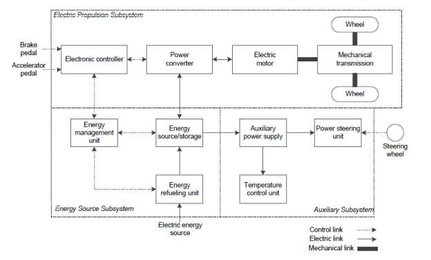
Figure 3: General EMU configuration block diagram
The electric propulsion subsystem consists of the motor drive, transmission device and wheels. The heart of this system is motor drive, comprising of the electric motor, power converter and electronic controller. The key requirements to specify an electric motor are given below;
- High instant power and high power density;
- High torque at low speed for starting and climbing as well as high speed and low torque for cruising;
- High efficiency over wide speed and torque ranges; and
- High reliability and robustness for various vehicle operating conditions.
The energy source subsystem consists of energy source, energy management unit and energy refuelling unit and auxiliary subsystem involves the power steering unit, temperature control unit and auxiliary power supply etc.
Based on the control inputs from the accelerator and brake pedals, the electronic controller provides proper control signals to switch on or off the electronic power converter, which works to regulate the power flow between the energy source and electric motor. The backward power flow is due to the regenerative braking of the EMU and this regenerated energy can be restored to the energy source, provided the energy source is receptive.
The energy management unit cooperates with the vehicle controller to control the regenerative braking and its energy recovery. It also works with the energy refuelling unit to control the refuelling unit, and to monitor the usability of the energy source. The auxiliary power supply provides the necessary power at different voltage levels for all the vehicle auxiliaries, especially the temperature control and signalling systems etc. [8]
For modern EMUs Permanent Magnet Synchronous brushless motor are the most common and used widely for the propulsion of the units and the corresponding power converter is a three-phase PWM inverter. In general a Lithium-based (Li-Ion) battery pack is used as energy source, and consequently the refuelling unit becomes a battery charger. The temperature control unit consists of a cooler and/or a heater. Figure 4 below shows the typical configuration of the EMU.
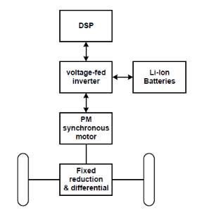
Figure 4: EMU drive train configuration
3.2.2 Different transmission options for EMU
Due to technological advancement and type of energy source as well as propulsion devices an EMU can have different configurations. This also depends on the type of body and specific requirement for the EMUs. Figure 5 shows six typical alternatives.
- Figure 5 shows the configuration of the first alternative, in which an electric motor replaces the IC engine of a conventional vehicle power train. It consists of an electric motor, a clutch, a gearbox and a differential.
- With an electric motor, which has constant power in a long speed range, a fixed gearing can replace the multispeed gearbox and reduce the need for a clutch. This configuration not only reduces the weight and size of the mechanical transmission, but also simplifies the drive train control because gear shifting is not required.
- The electric motor, the fixed gearing, and the differential device are further integrated into a single assembly, while both axles point at both driving wheels.
- In this configuration the mechanical action of differential is electronically replaced by two electric motors operating a different speed, each of them drives one side wheel.
- In order to further shorten the drive train from the electric motor to the driving wheels, the traction motors can be placed inside a wheel (in-wheel drive). A thin planetary gear set can be used to reduce the motor speed and enhance the motor torque.
- By fully abandoning any mechanical gearing, the out-rotor of a low-speed electric motor can be directly connected to the driving wheel. Figure below shows a gearless arrangement in which the speed control of motor is equivalent to the control of the wheel and hence the vehicle speed. However, this configuration requires the electric motor to have a higher torque to start and accelerate the vehicle.
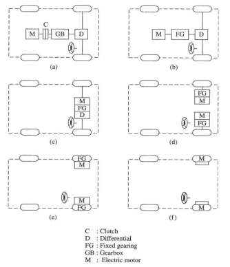
Figure 5: Different EMU configuration
As mentioned before, the system configuration of an EMU propulsion system can adopt a single motor or multiple motors, as shown in the following Figure 6 and 7. While these two configurations have their own merits, both of them are adopted in modern EMU technology, however the use of single-motor configuration is most popular.
Below are some of the main reasons for choosing these configurations:
- Costs – the multiple-motor are a completely new configuration and require a complete redesign of OEMs production plants and consequently very high investments which is not justified by the current market demand.
- Maintenance benefits – the number of components is inversely related with the reliability of the system, even if in the multiple-motor configuration there is not a differential unit, affected by wear and ageing.
- Weight – the single-motor structure is lighter, even if the multiple-motor one allows a better distribution of the mass through the vehicle. [3][7]
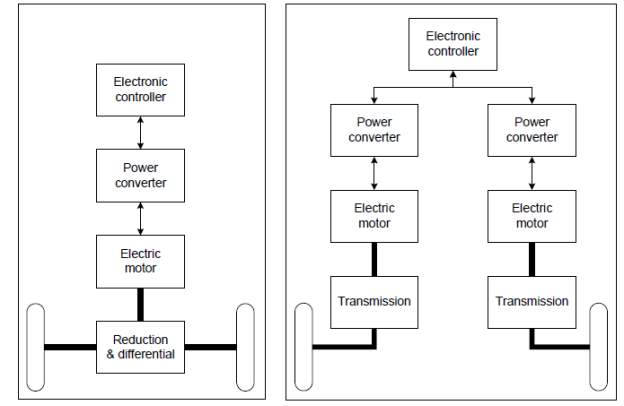
Figure 6: Single motor configuration Figure 7: Multiple motor configurations
3.2.3 Preferred configuration arrangement for an EMU
As described in figure 5 earlier the different configuration, the evolution from conventional configuration to innovative configuration is noted with major changes within gearboxes and differential concepts. The concept of variable gearing is not suitable for the DMUs due to torque-speed characteristics of the engine which cannot offer the desired performances in a complete driving cycle, such as high torque for hill climbing and high speed for cruising. So primarily the concept of variable gearing has always been applied electric vehicles. The modern EMUs can achieve the requested performance with fixed gearing transmission, which can replace variable gearing, reducing the overall complexity, size, weight and maintenance costs.
A more controversial aspect is the possibility to replace the differential device, Figures 8 and with two or even four electric motors coupled to the driving wheels (as anticipated in Figures 5d, e and f).
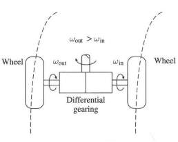
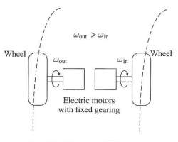
Figure 8: a) Mechanical differential gearing (left) b: Electrical differential gearing (right)
The differential action can be supplied by several motors, controlling the speed of each wheel independently with an electronic control rather than a mechanical device, as in Figure 8b.
In this arrangement, the weight is better distributed than in the conventional one, but negatively, the use of double motor and power converter causes an increase of initial costs and an increase of number of components, potentially affecting the reliability.
The ultimate solution for an EMU configuration is the in-wheel drives, as shown in the relative configurations in Figure 5 e and f. By placing the motor inside the wheel, mechanical transmission path between motor and wheel can be minimised or remove.
In a high-speed inner-rotor motor (figure 9), a high-speed reduction becomes necessary to attain a realistic wheel speed. On the other hand, the transmission can be totally removed when a low-speed outer-rotor motor is used. In this case, the outer rotor itself is the wheel rim, and no gears are required (figure 9b). A modern EMU can have any of these configurations. The high-speed inner-rotor motor has the advantage of smaller size, lighter weight and lower cost, but needs an additional planetary gear set; the low-speed outer-rotor motor has the great advantage of gearless and simplicity but it is heavier, bigger in size and more expensive.
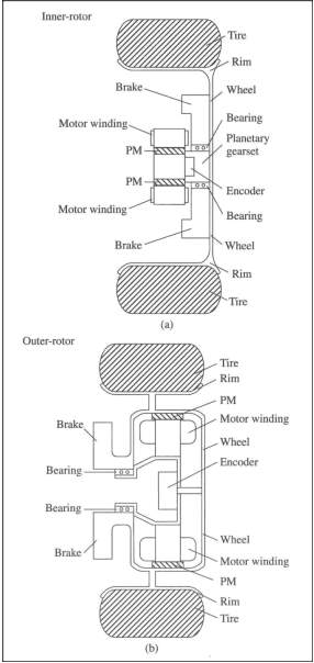
Figure 9: In wheel drive configuration
3.3 Component function and operation of an EMU
An overview of the modern EMU is given in this section along with its propulsion system configurations. A number of combinations of power unit are possible to produce necessary power for the EMU. This section also compares the most appropriate electric motor operation and characteristics. The technologies of power converter and energy source are overviewed, as well as of the electronic control systems. A base evaluation of the reliability of the entire power train is made by the Reliability Block Diagram (RBD).
The electric propulsion subsystem is the heart of an EMU and its main purpose is to link energy source to wheels, converting electric energy into power to move the vehicle with high efficiency and meeting the required performance levels. A typical electric propulsion system consists of:
- Electric motor;
- Electronic controller; and
- Power converter.
Mechanical energy is supplied by the electric motors converting electric energy gained through pantograph to kinetic energy into wheels, and can generate electricity during the braking application to recharge energy storage. Regenerative braking is a key process in modern EMUs and is used widely as it enhances vehicle efficiency by 20 – 25 %. The power converter supplies the electric motor with the appropriate current and voltage. Electronic controller provides control signals to power converter and so it controls the electric motor behaviour in order to achieve the requested torque and speed, according to commands from the driver. [8][11]
In the following Figure 10, the functional block diagram of electric propulsion system is shown, listing some possible devices used for each unit. The choice of components and shape mainly depends on three factors:
- Driver Interfaces;
- Vehicle constraints; and
- Energy source.
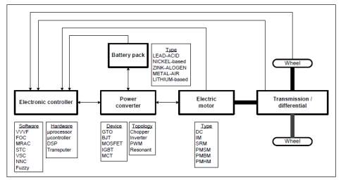
Figure 10: Block diagram for an EMU and technical description[8]
Driver interface depends on performance and driving cycles. Vehicle constraints are linked with vehicle type, vehicle weight and payload. Electric propulsion subsystem depends on what kind of source is adopted, such as batteries, ultra capacitors, flywheels, fuel cells and various hybrid sources.
3.4 Electric motor
An electric motor is one of the key parts of an EMU and provides energy for propulsion. The operations requested to the vehicle motor vary widely during the driving cycle such as frequent start/stop, high rate of acceleration/deceleration (overcoming or braking phase), high torque at slow speed (hill climbing), high speed at low torque (cruising highways). Due to these particular reasons the specification for the motors and selection criteria is quite different from industrial devices, which operate on a narrow range of conditions.
Industrial motors are generally optimised at rated torque and speed; while EMUs need to match four/five times the nominal torque and speed for temporary acceleration and for cruising. Moreover, industrial motors work usually in fixed place instead of mobile vehicles with harsh operating conditions such as high temperature, frequent vibrations and bad weather. The motor drives for EMUs can be classified as two main groups, namely the commutator motors and commutator less motors, as shown in Figure 11.
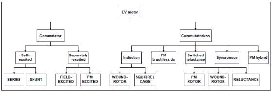
Figure 11: different types of electric motors and their configuration
The former refer mainly to the classical DC (direct current) motors, which need commutator and brushes to feed current into the armature, making them less reliable and suitable for maintenance-free and high speed. Nevertheless, in recent past DC motors have been prominent thanks to their mature technology and simple control.
The commutator less motors are now more commonly used than the conventional motors due to advanced technology and increased efficiency, higher power density, lower operating costs, greater reliability as well as very low maintenance. The absence of brushes and commutators ensures low failure probability as well as high reliability.
3.4.1 Types of electric motors for an EMU
The most commonly used electric motors in modern EMUs are induction motors, PM Synchronous motors, Switched Reluctance motors and PM Hybrid motors.
Induction motor
It is a widely accepted type of device for and EMU propulsion due to its low cost, high reliability and least maintenance, and at present, it is one of the most mature technologies among various commutators less motor drives. The main advantages of this type of motor are:
- Light weight
- Small volume
- Low initial cost
- High efficiency
- Low maintenance
These strengths can outweigh the major weakness of induction motors, namely the control complexity.
Permanent Magnet synchronous motors
By simply replacing the field winding of a DC motor with permanent magnets, PM synchronous motors can eliminate conventional brushes, slip-rings and field copper losses. The major advantages of this kind of motor are:
- High efficiency
- Compactness
- Ease of control
- Low maintenance
However, it also has a few drawbacks:
- High initial cost
- Limited constant power range
- Magnet demagnetisation
- Small speed range
Switched reluctance motors
SR motors have been recognized to have big potential for EV propulsion. They have the definite merits of:
- Simple structure
- Low initial cost
- Proper torque-speed characteristics
Although they hold these advantages, there are also some weaknesses:
- Design complexity
- Control complexity
- Acoustic noises
PM Hybrid motor
There are different kinds of hybridization, namely the PM and reluctance hybrid, the PM and hysteresis hybrid, and the PM and field-winding hybrid. Each type has particular advantages that are summarised as:
- High efficiency
- High power density
- Wide speed range
- Ease of control
- Low maintenance
- Quiet operation
The disadvantage of this kind of motor is lack of maturity and higher costs. Table 2 shows the results of comparative analysis by a grading system where each type of motor is evaluated for six major characteristics on a scale of 1 to 5. At the end of each column, there is the final rating. Induction motor and PM brushless motors are the most relatively acceptable for EMU use. On the other hand, conventional DC motors are leaving their leadership to the modern solutions.
| DC Motor | Induction Motor | PM brushless Motor | SR Motor | PM Hybrid Motor | |
| Power density | 2.5 | 3.5 | 5 | 3.5 | 4 |
| Efficiency | 2.5 | 3.5 | 5 | 3.5 | 5 |
| Controllability | 5 | 3 | 4 | 3 | 4 |
| Reliability | 3 | 5 | 4 | 5 | 4 |
| Maturity | 5 | 5 | 4 | 4 | 3 |
| Cost | 4 | 5 | 3 | 4 | 3 |
| Total | 22 | 25 | 25 | 23 | 23 |
Table 3: Evaluation of different EMU motors
3.4.2 DIRECT CURRENT (DC) MOTOR
The DC motors are classified in two categories, wound-field motor and primary motor. In the former, magnetic field is produced by a set of winding and it can be controlled by the dc current, in the latter magnetic field is made by permanent magnets and it is uncontrollable. Traditionally this type of motor has been widely adopted for the applications where there is requirement for adjustable speed, frequent start/stop, braking and reversing. The torque is produced by the Lorentz principle, which states that any current-carrying conductor placed within an external magnetic field (B) generates a force (F). If the conductor is a coil, than there is a torque, as shown in figure below. [12]
In order to keep the direction of the rotation same, DC motors need commutator and brushes, which periodically reverse current direction between rotor and stator. These components cause the principal drawbacks of this kind of motor. Commutator limits the motor speed and generates torque ripples; brushes are responsible for friction and wear, hence require periodic maintenance.

Figure 12: DC motor operation illustration; b: field and armature control of the motor
During the starting phase of the EMU i.e. from zero to base speed, rotor coil voltage must be increased proportionally with the increase of speed (armature control). At the base speed, the armature voltage reaches the rated value and cannot be further increased. In order to reach higher speed it is possible to weaken the magnetic field (field control), keeping constant armature current. The torque produced drops with the increase of speed and the output power remains constant, as shown in figure 12b.
3.4.3 INDUCTION MOTOR DRIVES
One of the most widely used alternatives for DC motors is the induction motor. It is a type of AC motor (alternative current) where power is supplied to the rotor by electromagnetic induction. There are two types of IMs namely wound-rotor and squirrel cage. Squirrel cage is not used very often due to size, maintenance and cost of the same. [3]
Induction motor has some important advantages such as low cost, ruggedness, easy to maintain, lightweight and high efficiency. On the other hand, the principal problem is the complexity of speed control, which can be solved only with advanced electronic technology and modern control solutions, increasing the total cost of propulsion system.
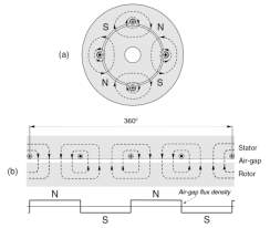
Figure 13: Operational principle of an Induction Motor [12]
3.4.4 PM SYNCHRONOUS MOTOR DRIVES
A permanent magnet synchronization motor or PM Sync motor is mainly divided into two categories; PM DC motor drive; PM AC motor drive. Due to no brushes and commutators, the latter is usually named PM brushless motor drive. This kind of drives is the most capable to compete with induction motor drives for electric propulsion. Their advantages are summarised as following:
- since the magnetic field is excited by high-energy PMs, the weight and volume can be reduced for a given output power (higher power density);
- Greater efficiency than induction motor, thanks to the absence of rotor copper losses;
- since the heat mainly originates in the stator, it can be more easily dissipated;
- Higher reliability, since PM excitation presents low risks of manufacturing defects, overheating or mechanical damage.
The system configuration of PM brushless motor drives is similar to that of induction motors, such as single or multiple motors configuration. Basically, the single-motor configuration consists of a PM brushless motor, a voltage-fed inverter, an electronic controller and reduction & differential gears. PM brushless motor is not restricted to be three-phase. In fact, a higher number of phases allow reducing phase current and current rating of power devices. These motors can be further classified in three categories:
- PM synchronous motor (PMSM);
- PM brushless dc motor (PMBM); and
- PM hybrid motors (PMHM).
3.5 Motor control system
PMSMs are fed by sinusoidal ac waves and use continuous rotor-position feedback signal to control the commutation, whereas PMBMs are fed by rectangular ac wave and use discreet rotor position feedback signals to control the commutation. Due to the rectangular interaction between flux and current, the PMBM has the ability to produce higher torque and by specially arranging the stator winding and flux path, it has superior dynamic performance as well as flexible controllability. Easy and flexible control system gives PM AC motor advantage over the induction one. Figure 14 shows the block diagram for torque and speed control for a PM brushless motor drive. [8]
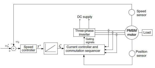
Figure 14: torque and speed control of the PM brushless motor
Torque, speed and current controller functions are embedded in the electronic controller module of the EMU commonly known as DSP. The desired speed ωr* is compared with the motor speed ωr, identified by a sensor, then Δω is processed by the speed controller producing the commanded torque T*. The desired current Is* is the result of a simple equation that relates current and torque. The current controller receives Is* and the motor position information from a position sensor, and then produces gating signal to control the inverter. By this gate signal, the inverter can produce the required phase current to properly control the electric motor torque. The current controller provides the properly sequenced gating signals to the three-phase inverter while comparing sensed currents to a reference to maintain a constant peak current control. The commutation sequencer causes the inverter to electronically commutate by using its position, acting as the mechanical commutator of a conventional DC machine.
Many high-performance applications include current feedback for torque control. At the minimum, a DC bus current feedback is required to protect the drive and machine from over current. Early permanent magnet motors suffered from the tendency for the magnets to be demagnetized by the high stator currents during starting, and from a restricted maximum allowable temperature. Much improved versions using high coactivity rare-earth magnets were developed to overcome these problems.[12]
3.6 Power converters
A power converter is an electrical device that links energy source with motor, feeding current with the proper characteristics (AC/DC, voltage and frequency). The evolution of power converter technology normally follows that of power devices, aiming to achieve high power density, high efficiency, high controllability and high reliability. There are several types of power converters, namely ac-dc, ac-ac at the same frequency, ac-ac at different frequencies, dc-dc and dc-ac. Dc-dc converter are usually named dc choppers, dc-ac are named inverters, which are respectively used for dc motor and ac motor drives.
Inverters are classified into two categories, voltage-fed and current-fed. The former is almost exclusively used for the EMU propulsion systems because it has a very simple construction and allows power flow in either direction. The inverter converts direct current (dc) from batteries to alternating current (ac) to drive the electric motor that provides power to the wheels. The inverter also converts ac to dc when it takes power from the motor-generator to recharge the batteries (regenerative braking).[8] A typical inverter adopted with induction motor or PM brushless motors is a 3-phase voltage-fed PWM inverter. PWM refers to the output waveform.
The electronic scheme of this kind of device is shown in Figure 15. This inverter has three legs (S1 and S4, S3 and S6, and S5 and S2) which feed phase a, phase b, and phase c of the induction motor. When the switches S1, S3, and S5 are closed, S4, S6, and S2 are opened, and phases a, b, and c are supplied with a positive voltage (Vd/2). Similarly, when S1, S3, and S5 are opened and S4, S6, and S2 are closed, phases a, b, and c are supplied with a negative voltage. All the diodes provide a path for the reverse current of each phase.[3]
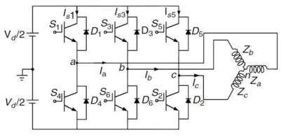
Figure 15: DC/AC three-phase Voltage-fed inverter
3.7 Electronic controller
An electronic controller is one another one of the most important parts of an EMU and provides control signals to power the converter to control the electric motor operations and supply the requested torque and speed according to command from the driver. The controller receives feedback signals from the vehicle about load parameters and conditions (actual speed driver request speed and battery status, etc.), it analyzes them and sends output to control behaviour and matches its performances. The control system is divided into three functional units; sensors, interface circuitry and processor.
Sensors translate physical parameters (such as speed, current level, temperature) into electric signals through the interface circuitry. These signals are fed into the microprocessor, which processes them and produces the proper outputs to control the vehicle. Sensors are very critical components with regards to reliability due to their working environment such as high temperature etc increasing the fault probability. In the last few decades the microelectronics technology has gone through evolution and latest microelectronic devices can be classified in three categories:
- Microprocessors;
- Digital signals processors (DSPs); and
- Microcontrollers.
Microprocessors act as the brain (CPU) of the electronic system, which decodes instructions and controls operations. DSPs are specialised processors which process needs of digital signal into sophisticated control algorithms for high performances of the motors. [13] A functional scheme of a DSP is shown in Figure 16. Further reliability considerations will be discussed in the following Chapters.
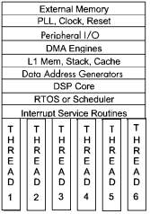
Figure 16: Digital signal processor – block diagram
3.8 Energy source – batteries
The energy source device is the most critical element in the development and spread of modern EMUs. In order to compete with the conventional petrol or diesel engine vehicles the energy source should cover the following points:
- High specific energy – key parameter related to the driving range;
- High specific power – the key parameter related to the acceleration and climbing capability;
- Long cycle life – defined as the number of deep-discharge cycles before failure;
- High efficiency – defined as the ratio between output energy and input energy; and
- Low life cycle cost – it consists of initial cost (design and manufacturing) and running cost (operational and maintenance). [8][16]
There are different kinds of technical solutions, namely rechargeable electrochemical batteries, fuel cells, ultra capacitors and ultrahigh-speed flywheels. Each one of them represents specific strengths. Currently Batteries are the most used solution as energy source due to these being most economical option. [17]
Batteries are electrochemical devices which convert chemical energy into electric energy (discharging) and vice versa (charging), so they have both functions of source as well as storage. There are several types of batteries are available in the market such as lead-acid battery, nickel-based battery, zinc-halogen battery, metal-air battery, sodium-β battery, and ambient-temperature lithium battery. [3]
The US Advanced Battery Consortium (USABC) is a R&D organization composed by US Department of Energy, Ford, Chrysler, General Motors and battery manufacturers, with the objective of fund research on advanced battery technology. This organization has set the long-term performance goals for batteries, as shown in Table 4.[18]
| Parameter (units) of fully burdened system | Minimum goals for long term commercialization | Long term goal |
| Power density (W/L) | 460 | 600 |
| Specific power – discharge
80% DOD/30sec5 (W/kg) |
300 | 400 |
| Specific power – regen
20% DOD/20sec (W/kg) |
150 | 200 |
| Energy density – C/3 discharge rate6 (Wh/L) | 230 | 300 |
| Specific energy – C/3 discharge rate (Wh/kg) | 150 | 200 |
| Specific power / specific energy | 2 / 1 | 2 / 1 |
| Total pack size (kWh) | 40 | 40 |
| Life (years) | 10 | 10 |
| Life 80% DOD (Cycles) | 1,000 | 1,000 |
| Power & capacity degradation
(% of rated spec) |
20 | 20 |
| Selling price 25,000 units @ 40 kWh ($/kWh) | <150 | 100 |
| Operating environment (°C) | -40 to +50
20% performance loss (10% desired) |
-40 to +85 |
| Normal recharge time | 6 hours
(4 hours desired) |
3 to 6 hours |
| High rate charge | 20% – 70% SOC7 in <30min
@ 150 W/kg (<20 min @ 270W/kg desired) |
40% – 80% SOC
in 15 minutes |
| Continuous discharge in 1 hour – no failure (% of rated energy capacity) | 75 | 75 |
Table 4: Long term performance goals for batteries as set out by USABC
USABC’s aim is to deliver Electric vehicles as close in performance as to internal combustion engine vehicle as possible. The table below shows the specification for some of the best performing.
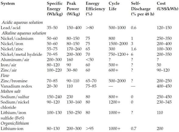
Table 5: Status of batteries performances for automotive applications [3]
Lithium has lightest atomic weight and the highest negative potential, so it presents very interesting characteristics from an electrochemical point of view. Lithium-based battery allows a high electrochemical potential and provides the largest energy density for weight, providing to EVs the greatest performance characteristics in terms of acceleration and range. Two different types available for lithium-based battery:
- Lithium-Polymer (Li-P) battery
- Lithium-Ion (Li-Ion) battery
The Li-Ion has been identified by many battery manufacturers to be the most efficient battery. As shown in Table 5 above this energy device presents the higher efficiency rate (>95%), one of the major power density range (200-300 W/Kg), a very high specific energy (80-130 Wh/Kg) and wide life duration (more than 1000 deep-discharge cycles).
Li-ion batteries produce the same amount of energy as NiMH cell, yet they are 40% smaller and almost half the weight. This is one of the most important aspects for considering these as energy storage.
3.9 Reliability block diagram
The Reliability Block Diagram (RBD) is a useful analysis tool to evaluate the reliability of complex systems. By RBD method, the analyst represents by simple blocks the functional components of the system, linking them in serial path or in parallel path respectively if the fault of a single unit affects directly the working of the entire system, or if this fault can be bypassed through an alternative path. The main objective of RBD is to represent the reliability relations between components and system. Each component can reside in one of two mutually exclusive operational states: functioning adequately or failed.
There are some simple rules to produce a Reliability Block Diagram as follows:
- Each block can represent a subsystem of components, whose reliability could be calculated;
- Blocks are represented in a serial path if all of them are required to allows entire system to run;
- Several series of blocks are represented in parallel paths if is enough that one of them is working properly;
- A failed block can be replaced by a “open circuit”;
- A block with 100% reliability can be replaced by a “short circuit”;
- RBD method refers to a maintenance strategy without repair activities: a failed block is not repaired if the system still works;
- Blocks failures are independent each other.
Some examples of block diagrams are shown in the following Figure 17 below.
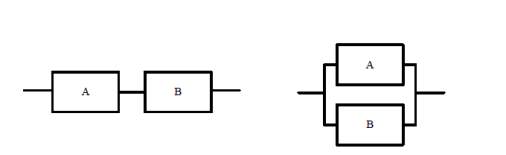
System requires both subsystem A and B System requires A or B
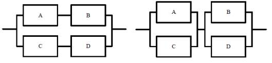
System requires A and B or C and D System requires A or C and B or D
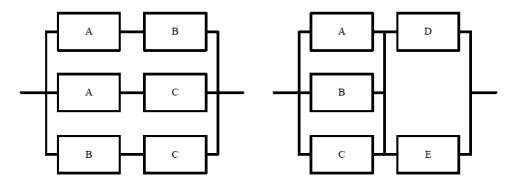
System consists of 3 subsystems A, B and C
and requires any two of these o perform correctly
System is satisfied by any of the following:
A and D perform correctly
C and E perform correctly
B and either D or E perform correctly
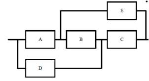 System is satisfied by any of the following:
- A and B and C perform correctly
- D and C perform correctly
- A and E perform correctly
There are some rules to calculate the reliability of the whole system, assembling single blocks of the RBD. [20]
- The reliability of a serial path of blocks is the product of all blocks reliability;
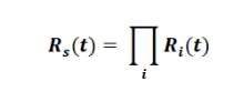
(1)
Rs (t) = system reliability
Ri (t) = component reliability
- Reliability of several blocks in different parallel paths is calculated according to the following equation:
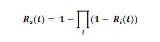
(2)
The units in parallel systems are referred to as redundant units, since at least one of the units must succeed for the system to succeed. That’s why adding redundancy is one of several methods of improving system reliability. In general, reliability of a serial path is lower than that of any of its members; whereas reliability of a parallel system is higher than that of the most reliable block. [20]
Estimation of system reliability is a very critical and complex activity; it’s strictly linked to the failure rate λ (t) of each component and a wide number of failure data is necessary to calculate it with good approximation.The general equation which connects reliability and failure rate of a component is the following:
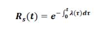
(3)
This equation can be easily simplified if component has a constant failure rate in the time. This is the case of electronic units which are not affected by wear and so failure probability does not increase over time.
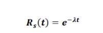
(4)
EMUs consist of a number of electric and electronic units, so maintenance strategy has to consider failure behavior of this kind of components.
The main components of the system are the following:
- Digital Signal Processor;
- Propulsion battery pack (Li-Ion);
- 12V auxiliary battery;
- Power inverter;
- Electric motor drive;
- Fixed reduction gearing.
Digital Signal Processor (DSP) is the “brain” of the vehicle; it receives and sends signals to each unit in order to obtain the request performances. Battery pack is the energy source and energy storage which supplies power to the electric motor. Auxiliary battery is the energy provider of the auxiliary subsystem (cooler ad heater, steering unit, radio, etc.).
Power inverter is the electronic device that links energy source with motor, feeding current with the proper characteristics (AC/DC, voltage and frequency). Electric motor supplies mechanical energy converting electric one from batteries to wheels. Fixed reduction gearing plays the role of connect electric motor to the wheels shaft. Considering the behavior of the vehicle, each component is necessary to allow the system to work. Without any of these units it’s impossible to have the correct operation. The proper way to show this kind of system is a serial path, as described in the following RBD (Figure 18).
| Electronic | Charging | Propulsion | 12V auxiliary | A.C. Electric | Fixed | |||||||
| controller and | Inverter | reduction | ||||||||||
| system | battery system | battery | Motor | |||||||||
| sensors | gearing | |||||||||||
Figure 18: EMU key component Reliability Block Diagram
One of the weaknesses for this series structure is the absence of stand by units, creating a need for higher reliability. An efficient operation of each component is absolutely required to allow the whole system to run. Considering that great part of the system is composed by electronic and electric components, marked by a constant failure rate, it’s very important to predict the Mean time between failuresof each of them, in order to apply a preventive maintenance strategy to avoid systembreakdown
Chapter conclusions
In this chapter, the structure of a conventional train has been introduced in order to explain the first idea of electric vehicles, replacing conventional components with electric ones. Then, several configurations of Electric vehicles (EMUs) have been described, with pros and cons analysis of functions and operations. Particular considerations have been reserved to the differential unit and mechanical transmission, identifying the potential offered by the new electric propulsion (in-wheel drive and electronic differential).
This chapter discussed the components of an EMU with different configurations and technical solutions have been compared on their specific features. In particular, the following parts of a typical EMU have been discussed:
- electric motor;
- electronic controller;
- power converter; and
- Energy source.
Finally, prime maintenance aspects have been considered and discussed through the Reliability Block Diagram. The system is a serial path and its reliability is strongly related to the less reliable component, according to equation (1).
As result of this literature review, a typical power train configuration (Figure 19), currently adopted by OEMs, is so described as a single-motor drive train, mainly consisting in a ≈60-80 kW Permanent Magnets synchronous motor drive, with fixed reduction gearing and differential to transmit power to the wheels. The propulsion energy source and storage consists in a ≈22-24 kWh Li-Ion battery pack [9] [10]. The power converter unit is generally a voltage-fed inverter, controlled by a Digital Signal Processor. Finally, a conventional 12V battery is required to supply the auxiliary subsystem of the vehicle, taking energy from the Li-Ion battery through the DC/DC converter.
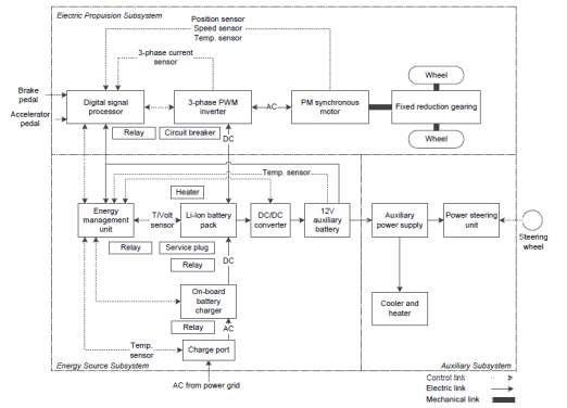
Figure 19: Typical EMU configuration, Illustration of control, electric and mechanical links
4 Chapter Three – Methodology
A literature review has been carried out on technologies related to EMUs and its subsystem such as traction, electronic control systems and energy storage system. We have also considered different configurations with a comparison via pros and cons analysis. Latest academic papers, reference books, industrial publications and individual theses have been studied for understanding the typical failure modes and relevant PM tasks of an EMU.
The author has taken Reliability Centred Maintenance approach for the purpose of this work to produce a long term maintenance program for EMUs. In this section the key factors will be described for choices regarding RCM, its base principles as well as the logic steps and phases.
4.1 Reliability Centred Maintenance
Reliability Cantered Maintenance or RCM is maintenance method to logically identify and prevent plant failures. As per the formal definition RCM is described as “a process used to determine what must be done to ensure that any physical asset continues to do what its users want it to do in its present operating context”. [21]
With the increased numbers of plants, assets and type of machinery as well as technological advancements, the maintenance has changed very much over the last few decades. Furthermore in a bid to improve safety, environmental impact and to minimise costs maintenance methods have led to more organised and systematic approach. RCM is a method which compliments these challenges is best possible way.
There are several ways to apply the RCM method, different start points of the logical path (i.e. system level or component level) and different analysis tools (i.e. FMECA or COFA), but the common principles of the method are clear. RCM is focused on preserving system functions, classifying components in categories in order to find the most appropriate maintenance tasks to keep the system available, as close as possible to the 100% threshold.
Within RCM technique there are seven fundamental questions which are used on the assets under review and they are as follows; [21]
1. What are the functions and associated performance standards of the asset in its present operating context?
2. In what ways does it fail to fulfil its functions?
3. What causes its functional failure?
4. What happen when each failure occurs?
5. In what way does each failure matter?
6. What can be done to predict or prevent each failure?
7. What should be done if a suitable proactive task cannot be found?
This chapter will highlight the logical path used by the author in order to analyse EMU maintenance as well as discussing the steps taken to produce the worksheet.
4.2 Fundamental concept of RCM method
Following are the three main steps for applying RCM to a particular asset or plant.[22]
Phase 1 – identify equipment, which are important for the plant’s safety, production and asset protection. These are the parts of the system, which require a preventive maintenance strategy to prevent failure, in order to preserve critical equipment functions.
Phase 2 – specify the type of preventive maintenance tasks and the periodicities that should be prescribed to the equipment identified in phase 1.
Phase 3 – execute the activities specified in the previous phase and control if the planned scheduling is observed.
A first output of the method is the classification of the system components, at the end of the first macro-phase, in order of priority as following:
Critical component: when the occurrence of the component failure is evident and causes an immediate unwanted consequence at the plant level, from a safety, operational and environmental point of view. For these reasons, this kind of failure has to be avoided before its occurrence by Preventive Maintenance (PM) tasks.
Potentially critical component: this is probably the most subtle concept in RCM approach and is strictly correlated to the meaning of hidden failure.
Firstly, a failure is hidden if there is no indication of failure and there are no operational consequences to the facility when it happens (i.e. the failure in one or more component in a parallel design without indication of failure for each individual component). So, a component should be classified as potentially critical if its failure is hidden but has the potential to become critical just with an additional failure, or with the duration of time. That is why a multiple-failure analysis is required when this kind of situation is detected. A potentially critical component refers to the potential consequence of failure to the plant, after the hidden failure of that component has already occurred, and there is no evidence of this event.
The difference between critical and potentially critical components is that the former manifest them immediately and the latter are hidden without consequence until a second failure occurs (in most cases) or certain time duration occurs.
Commitment component: this definition is related with those components which have regulatory, environmental, occupational, safety, health and administration (OHSA) commitments that must be fulfilled, requiring a PM strategy to preclude components from failing and causing a commitment to be missed.
Economic component: the failure of this type of component has economic consequence only and has no effect on system safety and operability.
Run-to-failure (RTF) component: to be classified as RTF, a component must have no safety, operational, commitment or economic consequence as the result of a single failure. Moreover, the occurrence of the failure has to be evident to operations personnel. A common mistake is to consider equipment as run-to-failure just because it has no unwanted consequences to the facility: the difference between RTF and potentially critical component is that the former’s failure has to be evident, while the latter’s one is hidden.
RTF components do not require preventive maintenance prior to failure, but then corrective maintenance is required in a timely manner after failure.
Quite often it occurs that several failure modes are detected for a single component, and those failure modes are classified in different categories each other (i.e. a critical failure mode and a RTF one): also, the final classification of that component is the most limiting and precautionary (i.e. critical).
A typical misunderstanding of meaning, and also of maintenance analysis, concerns the concepts of standby/backup function and redundant function.
- When a component performs a standby (or backup) function in a facility, it usually does not operate and is called to run only in case of failure of the normally operating component. Thus, if the backup should fail, an unwanted consequence at plant level could occur and the component is considered critical and PM task is required.
- Redundant components usually operate simultaneously. If individual indication of failure is evident, the components are identified as RTF, otherwise as potentially critical.
The logic tree used in the analysis to classify each component of the EMU drive system is described later in the section, with aim to specify the appropriate PM tasks.
4.2.1 Phase 1 – RCM implementation
This section talks about the various tools and steps taken to implement RCM method for the maintenance of EMUs. One of the main steps in this process is to define the asset reliability criteria. [22]
Asset Reliability Criteria (ARC)
Defining ARC involves identifying all the unwanted consequences of failure, concerning safety and operability that can occur in the analysed plant which must be prevented. Economic criteria are separate from safety and operability criteria and will be discussed later, as well as commitment components that are determined by the commitment requirements.
Component functional failures that can trigger one or more asset reliability criteria will lead in a component classification of either critical or potentially critical. Also, components will be classified as following:
- Critical for safety or operability concern;
- Potentially critical for safety or operability concern;
- Commitment;
- Economic.
Any component with one of these classifications should have a PM strategy to prevent its failure, or a design change should be implemented if an effective PM task cannot be specified.
The asset reliability criteria specified for safety and operability concerns related to EMU is shown below;
| Asset Reliability Criteria for EMUs | |||||||
| Safety | |||||||
| 1.No compromise to passenger 2.personnel safety |
|||||||
| Operational | |||||||
|
|||||||
|
|||||||
|
|||||||
|
|||||||
RCM COFA logic tree, potentially critical guideline and economically significant guideline
The classification of components follows a simple logic path, that begins by identifying critical components, than potentially critical, than commitment, than economical components and finally run-to-failure components, in order of importance.
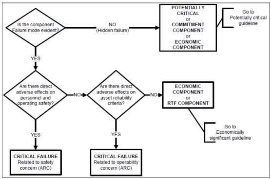
| Potentially critical guideline
Can the component failure, in combination with an additional failure or initiating event, or over time, result in an unwanted consequence that has a direct adverse effect on one or more of the asset reliability criteria? If YES, this is a potentially critical component. It could be potentially critical for safety or for operability concerns depending on its consequence of failure. If NO, is the component associated with a commitment? If it is, this is a commitment component. If it is not associated with a commitment, proceed to the following Economically Significant Guideline |
Economically significant guideline
If YES to any of the above questions and a PM are further justified by the Economic Evaluation, this is an economic component. If NO to all of the above, this is a run-to-failure component (RTF). |
This logic consists in a system of filters, through which all component failure modes have to pass. The critical components are identified by the COFA logic tree, the first filter. Potentially critical components are detected by the second filter, Potentially Critical Guideline. Those components making it through the first two filters then must pass through the commitment filter, included in the Potentially Critical Guideline. Fourth filter consists in the Economically Significant Guideline. If a component passes through all filters, it is classified as RTF.
The Consequence of Failure Analysis (COFA) Worksheet
The COFA worksheet is the main document produced in the phase 1 of RCM process, regarding the identification and classification of failure modes for each component. This worksheet integrates the COFA Logic Tree and the two guidelines, and its structure runs the RCM logic, as following: [22]
- COLUMN A: Specification of component I.D. and description;
- COLUMN B: Description of all function of the component; there are several functions for each component, the functions are the explanation for why the component is installed and preserving these functions is the main objective of the maintenance program.
- COLUMN C: Description of the ways each function can fail; typically functional failures are the opposite of functions.
- COLUMN D: Description of the dominant component failure mode for each functional failure; the failure modes are the several ways a component can fail to provide a specified function.
- COLUMN E: Is the occurrence of the failure evident? The answer to this question comes directly from COFA Logic Tree. The failure must be evident during normal activities, and it can happen thanks to indication alarm, or by routinely performed rounds or by the unwanted consequence at facility level.
- COLUMN F: Description of the system effect for each failure mode; the ultimate aim of the analysis is to identify the consequences of failure at facility level, note that hidden failures have not system effects.
- COLUMN G: Description of the consequence of failure based on the Asset Reliability Criteria; these consequences are at plant level and they are identified for each failure mode.
- COLUMN H: Criticality classification of each failure mode;
- COLUMN I: Criticality classification of the component; there could be different classification for the same component: the final one defaults to the highest level, according to the classification ranking.
At the end of the COFA Worksheet, the first phase of RCM process can be considered complete.
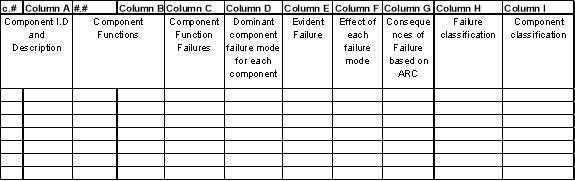
Table 6: COFA worksheet sample
4.2.2 Phase 2 – Preventive tasks selection
In this phase of RCM process, preventive maintenance activities are specified to address the causes of failure identified in the previous phase. There are three main categories of PM task: [22]
- Condition Based: this kind of task is addressed to know the real condition of the equipment by measuring, monitoring or analysing activities. Predictive maintenance (PM) tasks, such as vibration analysis, oil analysis, thermography, etc., refer all to condition directed maintenance.
- Time based: These tasks generally includes replacements, overhauls, or restoration of component at planned periodicity.
- Failure finding: is a strategy to ascertain, at a periodic interval, whether a component is already failed or not, before it results in a plant level consequence. That is why it is a proper activity only for hidden failures.
The PM task selection logic tree
The first tool used to approach the phase 2 of RCM process is the following logic tree, used to identify what kind of PM activity is required for each failure cause identified in the COFA Logic Tree. The preferable task is a nonintrusive one, so it is firstly evaluated if a predictive maintenance is applicable.
The second choice is a time-directed task, which usually is intrusive and could require downtime. A failure-finding task can be applicable only to potentially critical components, and it is the choice if a task to prevent the failure cannot be found. Finally, if no PM task is selected for the component, the alternative solutions could be a design change or accept the risk of the failure.
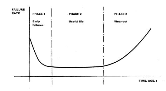
The condition-based maintenance is preferred to the time-based because, when a component is replaced or overhauled, its lifetime is restored but its failure probability increases highly for two reasons: premature failure and infant mortality, according to the common rule described by the “bathtub” curve, Figure 20.
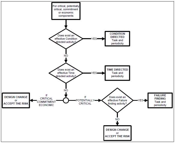
Figure 21: PM task selection Logic tree[20]
4.2.3 The PM task worksheet
After COFA Worksheet and PM Task Logic Tree, it is possible to issue the last document of the phase 2 of RCM process, the PM Task Worksheet that takes results from the previous analysis, as following:
- COLUMN A: component I.D. and description (from COFA Worksheet);
- COLUMN B: what were the consequences of failure? (from COFA Worksheet);
- COLUMN C: describe each dominant component failure mode (from COFA Worksheet);
- COLUMN D: describe the vehicle effects for each failure mode (from COFA Worksheet);
- COLUMN E: criticality classification of the component (from COFA Worksheet);
- COLUMN F: describe the credible failure cause for each dominant failure mode;
- COLUMN G: describe the applicable and effective PM task for each failure cause (from PM Task Logic Tree);
- COLUMN H: define frequency and interval for each pm task (from PM Task Logic Tree);
- COLUMN I: is a design change recommended?
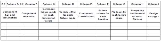
Table 7: PM Task Selection sheet sample
Each failure mode has one or more PM tasks to address the same. Therefore, a single component may have several different PM activities associated with it. The PM Worksheet is where the piece of parts (or subassemblies) of the components are introduced. These parts are the credible causes of failure, such as bearing failures, motor winding failure, and plug-in failure.
4.2.4 The Economic evaluation worksheet
The evaluation of PM activities for economic component needs further analysis. These types of component results in a monetary cost of labour and/or material. So a break-even point analysis is required between the cost of failure and the cost for performing a PM to prevent the failure. To allow this equation every cost must be calculated annually.
4.3 FMECA vs. COFA
The common analysis format in RCM method is FMECA (failure modes, effects and criticality analysis), which leads the analysts in the identification of components criticality, beginning from the functions of equipment at system level in a top-down way. An alternative format is the COFA (consequence of failure analysis). It includes all the same attribute of FMECA as well as additional attributes, but the analysis begins at the component level that is the final destination to detect consequences of failures. COFA also includes the decision process for determining the consequence of failure based on asset reliability criteria specified. COFA maintains clear separation among phase 1, identification of equipment, and phase 2, specification of PM tasks, resulting in a simpler format than FMECA. All these tools will be described later in the document. [21][22]
4.4 Labelling of asset component
The very first stage of RCM analysis is the classification and labelling of the system and its components. Labelling of components is a basic activity and it allows different software to link efficiently under a unique code to generate a lot of different information, using CMMS software, ERP software, database, etc.
Multiple data can be associated to a component label, such as component functions, risk classification, PM tasks, and even warehouse location of replacement parts, supplier, price and date of warehousing etc. It is very important to define a method to produce standard labels for each component. In this paper, the entire structure has been divided in three subsystems. Electric Propulsion Subsystem, Energy Source Subsystem and Auxiliary Subsystem; only the first two of these are considered in the RCM analysis.
- The structure of a label consists in several sections, to define each component uniquely:
- The subsystem in which the component is placed;
- The general function of the component (i.e. motor, battery, controller);
- The particular typology of the component (i.e. PM motor, Li-Ion battery)
The labelling of each component analysed is shown in the table below.
| Electric propulsion subsystem (EP) | Energy source subsystem (ES) | |||
| LABEL | DESCRIPTION | LABEL | DESCRIPTION | |
| EP-CTRL-DSP | Electronic controller, digital | ES-CTRL | Energy management | |
| signal processor | unit | |||
| EP-INV-3PH | Traction motor inverter, | ES-BAT-LIP | Li-Ion Battery Pack | |
| 3phase voltage-fed PWM | ||||
| Permanent Magnet | Battery on-board | |||
| EP-EMOT-PMSM | Synchronous traction | ES-CH-OB | ||
| charging unit | ||||
| motor | ||||
| EP-GR-PLAN | Planetary reduction gear | ES-CH-PT | Charge port | |
| EP-SNS-M-P | Motor position sensor | ES-BAT-HT | Li-Ion battery heater | |
| unit | ||||
| EP-SNS-M-S | Motor speed sensor | ES-BAT-12V | Auxiliary 12 V battery | |
| Voltage and | ||||
| EP-SNS-M-T | Motor temperature sensor | ES-SNS-12V | temperature sensor of | |
| 12V battery | ||||
| EP-SNS-ACC | Accelerator pedal sensor | ES-SNS-LIP-C | Li-Ion Battery current | |
| sensor | ||||
| EP-SNS-BRK | Brake pedal sensor | ES-SNS-LIP-T | Li-Ion Battery | |
| temperature sensor | ||||
| EP-SNS-INVPH | Inverter phases sensor | ES-PLUG-LIP | Li-Ion battery service | |
| plug | ||||
| EP-CIR BRK | Fail-safe circuit breaker | ES-SNS-CHPT | Charge port | |
| temperature sensor | ||||
| EP-REL-DSP | DSP relay | ES-CON-DCDC | DC/DC converter | |
| ES-REL-LIP | Li-Ion battery relay | |||
| ES-REL-CHOB | Charging relays | |||
| ES-REL-EMU | Energy management | |||
| unit relay | ||||
Table 8: Component Labelling Sample
Chapter conclusions
In this chapter the research process has been described, starting from the literature review of the EMU train system. The RCM analysis method has been presented, with particular attention to the logical steps of the process.
In this study, only the first two phases of RCM are applied, in order to produce a preventive maintenance program, and all the necessary tools, such as logic trees, guidelines and Asset Reliability Criteria, have been described.
Finally, all the components of the analysed system have been labelled, in order to better refer to them during the application of the RCM method.
5 Chapter Four – Results and findings
Each component of the traction subsystem and energy source subsystem is analysed using the COFA worksheet and PM task worksheet as shown in appendices. In this chapter of the paper the principal findings of the analysis will be reported, describing the main failure modes of those components, their criticality level and the Preventive Maintenance tasks identified to address these failure modes.
5.1 Components classification and effects of failures
One of the first steps of the Reliability Cantered Maintenance method is to identify the likely failure modesof components and classify them into their criticality. The COFA worksheet is a report template and a guide for the analysis. The same has been filled for the EMU maintenance planning based on the COFA logic tree and the guidelines as explained earlier in the methodology chapter.
As described by the Reliability Block Diagram in figure 17, large proportion of the components is classified as critical, suggesting that any failure to these components will directly affect the function of EMU and its systems. Based on the analysis, 22 out of 26 components have been classified as critical, 3 as potentially critical and 1 has classification of “run to failure”.
This kind of set up is of high risk where only one component failure can lead to complete vehicle shut down. According to the theory explained in the Paragraph in earlier section, the reliability of a series structure is given by the product of all components reliability, as in the following equation. [22]
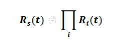
This suggests that each component must have a high reliability to keep the systems running which has been factored into the proposed planned preventive maintenance program. In some cases, a component has different classifications for different failure modes, so the final classification defaults in the most critical according to the ranking: Critical (safety concern), Critical (operability concern), potentially critical, Commitment, Economic and Run to Failure.
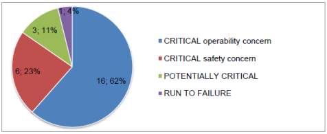
Figure 23: Component criticality classifications
It can be observed from the above graph that 85% of the components are critical and require a Single failure analysisbecause the failures are evident and with severe consequences. Only the 11% of components are potentially critical, therefore requiring a multiple failure analysis to address any of the hidden failures.
It can be summarized as the system needs an effective preventive maintenance program to ensure high reliability but o the other hand it is quite easy to identify failure modes and failure causes of the majority of components. Potentially critical components are, indeed, the important ones as their failure modes are hiddenand they have the potential to be critical in conjunction with additional failure. There type of components has to be analysed carefully to identify any failure links between components in order to address the root-causes by applying appropriate maintenance schedule.
It is important to notice that it has not been identified any Economic or Commitment component across the classification: as explained in the Chapter 3 Methodology, there is a standard process, explained in the COFA logic tree (Figure 3.1), to classify the components of the vehicles traction system, according to the RCM principles. From a reliability point of view it’s important to make decisions with caution and, indeed, for all the components considered in this study, except for one RTF, each failure mode has been classified as more critical than commitment and economical.
In the COFA worksheet, Appendix A, the likely effects of each failure mode have been identified, and the consequences have been categorized according to the Asset Reliability Criteria. These consequences at system level have been divided into 4 classes
- Vehicle shutdown;
- Power reduction;
- Range reduction; and
- Safety risks for users or maintenance operators.
In the following diagram the percentage of consequence for all the failure modes is shown: the most likely effect is the breakdown of the vehicle, which is the effect of almost half of the identified failure cases. This is an important outcome that addresses considerations on the criticality of the whole system and the importance of preventive maintenance.
Power reduction and Range reduction are, respectively the 21% and 24% of all consequences of failure, and Safety risk is the 6%.
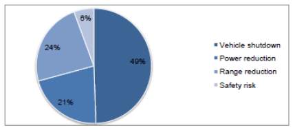
Figure 24: Consequences of failures, according to the ARC
5.2 Key component findings
In the Appendices it is possible to see the analysis divided in two worksheets, COFA worksheet and PM task worksheet, in which all the 26 component are processed.
In the COFA, 60 likely failure modes of the EMU components have been identified and, in the PM task worksheet, 100 failure causes linked with those failure modes have been detected. With the help of available resources such as academic papers, technical articles and industrial publications, it has been possible to produce a maintenance program, with Preventive Maintenance activities and relative periodicities, in order to address the failure causes of each component.
In this section of the paper the most important and interesting units of the EMU will be described, for further details refer to the Appendices.
Li-Ion battery pack
Code: ES-BAT-LIP
Classification: Critical operability concern
The battery pack is probably the most critical component of an electric power train for cost, performances and weight, and it needs particular attention.
The basic functions of this unit are:
– Provide energy to the PM electric motor through the inverter device;
– Provide energy to the auxiliary system (i.e. heather/air conditioned, radio, steering unit, etc.) through the 12V battery and the DC/DC converter;
– Store energy generated by the PM electric motor during regenerative braking.
The likely failure modes identified for the battery system are: [23] [24] [25]
– Short circuit;
– Overheating;
– Internal resistance increasing;
Over-charge;
– Over/under-current.
These failure modes and effects on the vehicle have been evaluated, according with the COFA logic tree, the Asset Reliability Criteria, potentially critical guideline and economically critical guideline in order to identify their criticality level. The battery pack is finally classified as Critical for safety concerns, and electronic system is vital to provide safe operations of this important unit. The following table shows the detection and protection devices for each safety related failure mode.
| Abnormal/abusive condition | Detection device | Protection device |
| Over temperature | Temperature sensor | Power switch is opened and insulates battery from load and rectifier |
| Over charge | Permanent screening of charging unit | Power switch |
| Over current | Charge current sensor | Power switch |
| Short circuit | Fuse status detector | Electrical fuse |
Table 9: Li-Ion Battery Pack safety system detection and prevention
The detection functions ensure that all the physical data are accurately measured. It seems obvious that, without reliable acquisition of data at intervals, electronics will not be able to protect the lithium cells or to optimise their performances. The data to be measured in a lithium-based battery may vary with the electrochemistry, but the following values are usually acquired by sensors: [23]
- each individual cell voltage;
- overall battery voltage;
- charge current;
- temperature of the cells;
- temperature of the electronics; and
- Ambient temperature inside the battery.
Protection is the most critical type of action as safety depends on it. A common type of protection is the fast opening of a reversible power switch, which isolates the battery system from the rectifier and the load. This isolation prevents a number of abusive conditions being applied to the battery. Over-charge is one example of an abusive condition imposed by the charger; a short circuit would be an example of a condition imposed by the load. When conditions come back to normal, the power switch closes. For all these reasons is evident that apply preventive maintenance activity to the electronic control system is as necessary as to the battery itself.
During the study appropriate preventive maintenance tasks have been identified for the Li-Ion battery pack, with the aim to address the root failure causes linked with each failure mode. The following PM activities are extracted from the PM task worksheet in Appendix B: [24][26]
| Failure causes | PM tasks for each failure cause | Frequency and interval for each PM task [months / miles] | |
| Connector/terminal failure | Check connector conditions and keep clean from moisture and chemical | 12 / 15,000 | |
| Failure of battery heater | Check the heater device operability | 12 / 15,000 | |
| Failure of battery sensor | Check the sensor operability | 12 / 15,000 | |
| Mechanical stress, ageing wear | Check the battery charge controller to verify the correct voltage settings | 12 / 15,000 | |
| Failure of Battery Control Module | Check the battery charge controller to verify the correct voltage settings | 12 / 15,000 | |
| Check and compare the voltage readings at the battery connections and at the controller | 12 / 15,000 | ||
| Failure of Battery Charger | Check all charging subsystems | 12 / 15,000 | |
Table 10: failure cause and PM tasks
Vehicle control unit – Digital signal processor (DSP)
Code: EP-CTRL-DSP
Classification: Critical operability concern
The Digital signal processor is the unit that receives signals from other vehicle’s components through sensors, analyzes these signals according to preinstalled algorithms, and sends feedback to control the vehicle’s functions and behaviour.
Due to advances in semiconductor technology, ever more complex DSP algorithms and applications are now feasible, which, in the same time, increase the complexity of the systems and products. As the complexity increases, the system reliability is no longer solely defined by the hardware reliability. The system reliability is increasingly determined by both hardware and software architecture and the level of design maintainability. [14] [25]
- The basic functions of this unit are:
- Provide control signals to power converter;
- Monitor vehicle status analyzing signals from sensors;
- Process inputs from driver (accelerator and brake pedals signals); and
- Calculate range considering battery state of charge.
The likely failure modes identified for the DSP are:
- Device cannot initialize;
- Device cannot provide proper output;
- Device cannot analyze input signals.
During the research appropriate preventive maintenance tasks have been identified for the Digital Signal Processor, with the aim to address the root causes linked with each failure mode. The following table 11 shows the PM activities with suggested frequency. The most critical cause of failure is about the software ability to communicate with vehicle’s different units: as a new technology, the control algorithm could have some lacks and bugs, and a careful updating of the software is vital.
| Failure causes | PM tasks for each failure cause | Frequency and interval for each PM task [months / miles] |
| Over/under power voltage | Check relay EP-REL-DSP | 12 / – |
| Software bugs | Update software and report known bugs to supplier, by internet access | If available |
| Incorrect installation | Check list of standard installation procedure | – |
| Abnormal output signal | Check I/O peripherals | 12 / – |
Table 11: failure causes and PM tasks
A few of the more common causes of DSP software bugs are due to: [14]
- Failure of interrupts to completely restore processor state upon completion;
- Failing to properly initialize or disable circular buffering addressing modes;
- Memory leaks, the gradual consumption of available volatile memory due to failure of a thread to release all memory when finished;
- Dependency of DSP routines on specific memory arrangements of variables;
- Conflict or excessive latency between peripheral accesses;
- Subroutine execution times dependent on input data or configuration.
These failure modes and effects on the vehicle have been evaluated, according with the COFA logic tree, the Asset Reliability Criteria, Potentially Critical guideline and economically critical guideline in order to identify their criticality level. The Digital Signal Processor is finally classified as Critical for operability concerns.
Permanent Magnet Synchronous traction motor (PMSM)
Code: EP-EMOT-PMSM
Classification: Critical operability concern
The electric motor has the main role of providing the traction power to the wheels and moving the vehicle but, in the case of pure-electric transportation, the range limitation induced manufacturers to research in solutions able to increase the efficiency.
The idea of Regenerative Braking goes on this direction, and it consists of the ability to generate electric energy during the braking phase of the car. The motor works as a generator charging the battery and increases the driving range of almost 20 – 25%.
The main functions of the electric motor are:
- Convert electric energy to mechanical energy;
- Convert kinetic energy to electric energy.
The likely failure modes identified for this component are: [28] [29]
- Winding failure;
- Bearings failure;
- Rotor and shaft failure.
Each of these principal failure modes has several failure causes that could generate the failure and in the PM worksheet the appropriate maintenance activities have been identified.
| Failure causes | PM tasks for each failure cause | Frequency and interval for each PM task [months / miles] | |
| Windings failure for Insulation breakdown | Keep motor clean with good air flow | – | |
| Windings failure for electrical fault | Store motor correctly away from moisture and chemical | – | |
| Windings failure for AC drive stress | Perform regular inspection | 24 / 30,000 | |
| Windings failure for cycling/flexing due to frequent start/stop | Keep motor clean with good air flow | – | |
| Bearings failure for mechanical breakage | Replace bearings | Corrective task | |
| Bearings failure for start/stop loss of lube film | Replace bearings | Corrective task | |
| Bearings failure for improper lubricant | Replace bearings | Corrective task | |
| Bearings failure for improper handling/storage | Replace bearings | Corrective task | |
| Store motor correctly away from moisture and chemical | – | ||
| Rotor failure for physical damage and corrosion | Check list of standard installation procedure | – | |
Table 12: failure causes and PM tasks for PMSM
Major part of maintenance tasks relate to keep the motor away from moisture, pollution, dust and chemical, both during the storing and the running, because these are the main root causes of failure. Indeed an electric motor has a very few components moving inside the housing, unlike a classic internal combustion engine, so friction is not a big problem and the reliability is much more high. On the other hand, the strong magnetic field generated by the rotor permanent magnets has an ageing effect on the bearings, which besides continue to have a long life cycle and assure duration.
According to Terry Harris [29], the failures of an electric motor can be divided into 6 main classes:
- Bearings;
- Stator winding (i.e. overload, water);
- External (i.e. environment, voltage, load);
- Rotor bar;
- Shaft or coupling.
In the following diagram are shown the average percentage of occurrence for these classes.
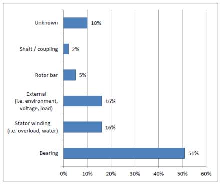
Figure 25: failure percentage of each component in PMSM motor
In the following table, the main failure causes are summarised for each constituent of the motor structure. [28]
| Motor component | Failure cause |
| Housing | – improper installation
– physical damage – corrosion – material build-up |
| Stator | – physical damage
– contamination – corrosion – voltage imbalance – high temperature – broken support |
| Rotor | – thermal stress
– imbalance – physical damage – contamination |
| Bearings | – improper handling/storage
– improper installation – misalignment – improper lubricant – start/stop loss of lube film – contamination |
| Fan | – physical damage
– ice build-up – corrosion |
| Winding / insulation | – contamination
– overheating – improper storage – moisture – thermal stress – AC drive stress |
| Shaft | – physical damage
– improper installation – improper manufacturing – corrosion |
Table 13: Failure Causes of each component in electric motor
Breakdown maintenance and overhaul jobs are handled at maintenance service provider facilities. However, breakdown maintenance for electric traction motors is not common due to their low failure rates, almost 4.0×10⁻⁵ (failure/hour). [25][28]
Power converter – 3 Phase Inverter
Code: EP-INV-3PH
Classification: Critical operability concern
The Inverter interfaces between the battery and the motor, addressing two main functions:
- Control the electric traction motor converting current at the required voltage;
- Charge the battery during regenerative braking, converting energy generated by the motor.
The basis failure modes identified for this device are mainly three:
- Device cannot initialize;
- Abnormal output to the motor;
- Abnormal output to the battery.
In the following table failure causes and proper maintenance tasks are shown to address these failure modes, with suggested frequency of application.[26][28]
| Failure causes | PM tasks for each failure cause | Frequency and interval for each PM task [months / miles] |
| Winding insulation breakdown | Check winding insulation condition | 24 / 30,000 |
| Insulation bushing breakdown | Check insulation bushing | 24 / 30,000 |
| Mechanical breaking, cracking, loosening, abrading, or deforming of static or structural parts | Keep device clean | 24 / 30,000 |
| Malfunction of protective relay | Check protective relay operability | 12 / – |
| Normal deterioration from age and corrosion phenomenon | Keep device clean | 24 / 30,000 |
| Overheating | Temperature monitoring, by DSP unit | – |
| Transient overvoltage disturbance (switching surges, arcing ground fault, etc.) | Switchgear inspection | 24 / 30,000 |
Table 14: PM task and failure causes for inverter
Fail-safe circuit breaker
Code: EP-CIR BRK
Classification: Critical safety concern
Circuit breakers are used in a power system to break or make current flow through power system apparatus, in order to protect an electrical circuit from damage caused by overload or short circuit. Its basic function is to detect a fault condition and, by interrupting continuity, to immediately discontinue electrical flow. Unlike a fuse, which operates once and then has to be replaced, a circuit breaker can be reset to resume normal operation.
Reliable operation of circuit breakers is critical to the ability to reconfigure a power system and can be assured by regular inspection and maintenance. [26] [28] [30] [31]
The likely failure modes identified for this critical component are:
- Stuck switch in on position;
- Stuck switch in off position.
The first failure has no evident effects on the vehicle, because the current is able to flow through the circuit, but in the case of electrical malfunction, the switch could not work. It is a typical example of hidden failure, impossible to detect without a proper preventive maintenance program, and in this particular case very dangerous for safety reasons. This failure mode is classified as potentially critical for the vehicle.
The second failure brings evident consequences on the system because electricity cannot flow through the power system, and it results in the breakdown of the vehicle, with possible consequences on safety. For this second failure mode, the component is finally classified as CRITICAL for safety concerns.
As the majority of electrical devices, the circuit breaker is often replaced in case of failure, but is vital to replace it before the occurrence of the failure: this is the reason for apply a preventive maintenance program, as shown in the following table
| Failure causes | PM tasks for each failure cause | Frequency and interval for each PM task [months / miles] |
| Normal deterioration from age | Inspect breaker-operating mechanism for loose hardware and missing or broken cotter pins, etc. Examine latch and roller surfaces | 12 / – |
| Loss or deficiency of oil or cooling medium | Clean and lubricate operating mechanism with a light machine oil | 12 / – |
| Persistent overloading | Replace component if contacts are badly worn or burned and check control device for freedom of operation | 12 / – |
| Exposure to abnormal moisture, chemicals or dust | Wipe and clean the insulating parts, including bushings | 12 / – |
| Misoperation or testing error | Check list of standard operation and test procedure | – |
Table 15: PM task and failure causes for circuit breaker
Temperature sensor of 12V battery
Code: ES-SNS-12V
Classification: Potentially critical operability concern
This sensor has the role of detecting and communicating to the Battery Control unit the thermal status of the auxiliary 12 V battery. The processor analyzes these data and controls the flux of energy through DC/DC converter, in order to avoid a failure of the battery.
This component is classified as potentially critical, because its failure is hidden, and only with the addition of another failure, as the failure of the battery, there is a consequence at the vehicle level. If this failure is made evident by the Vehicle Control System (DSP), then the Temperature sensor could be classified as a Run to Failure component, and replaced after its breakdown. In the following table are shown the PM tasks planned for this component and relative periodicity.
| Failure causes | PM tasks for each failure cause | Frequency and interval for each PM task [months / miles] |
| Incorrect installation | Check list of standard installation procedure | – |
| Connector/terminal failure | Check connector conditions and keep clean from moisture and chemical | 36 / 45,000 |
Table 16: Failure cause and PM task for temperature sensor
5.3 Discussion
Other than the Li-Ion battery and the final gearing, EMUs are much less likely to suffer from ageing wear compared to conventional ICE trains or DMUs. The majority of failures are originated from electric circuit problems and manufacturing issues. [25]
One of the main reasons for that is the EMUs has less components and component links than a conventional vehicle. As explained earlier sections of this chapter, the reliability of a serial system is inversely proportional to the number of its constituents. Moreover due to advanced technology within the electric propulsion, there are few components in mutual contact with each other, so reducing friction. On the contrary, ICEVs have numerous moving parts such as valves and cams, which increase the failure occurrence and the costs for spare parts.
In general, maintenance for electric cars is relatively low, almost 25 – 50% less than for conventional vehicles [33]. The future development, that likely will have the ability to increase the reliability of electric vehicles, relates with Predictive maintenance with on-board failures self-detection systems. Prognostic methods, with the capability of predicting system degradation before breakdown, are very promising and more affordable on electronics systems than mechanical systems.
Thanks to condition monitoring technologies, the ability of self-detection and anticipation of failures is much increased. Early detection of the likely critical failures relies on capabilities of the electronic controller, both software and hardware. Further investigation and testing are important for EMU trains technology development.
The on-board predictive maintenance (PdM) application could have more advanced systems with latest sensors which detect the conditions of the single components and communicate with a processor. The calculator unit has to translate the signals in readable data and compare them with threshold values.
In general, on-board and off-board PdM for electric motor systems mainly refers to vibration analysis, thermal analysis and ultrasound analysis. However, in the case of EMUs, the operational conditions have to be considered very carefully and the affordability must be evaluated by a cost/benefit analysis.
A very important development suggested for EMUs refers to the capability to communicate real-time relevant vehicle health data to OEMs. Communication systems are, at the present time, mature and reliable to provide an effective feedback to the manufacturers, creating the conditions for a real continuous improvement of the product and the service to the customers. Indeed, the final objective of the maintenance strategy is to increase the customer satisfaction, and reliability is one of the most important factors influencing asset owners.
5.4 Chapter conclusions
This chapter describes some general considerations on the reliability of the EMU and its sub component. Below are some of the main points based on these discussions earlier in this chapter;
- Electric traction systems are much more reliable than DMUs, with a lower number of components as well as less moving components in contact with each other;
- Battery sub system is the most critical system with smaller life as compared to other sub systems.
- As described in the RBD diagrams earlier in this report, it is noted that an EMU has a series structure; hence most of the components are classified as critical.
- In case of a major failure entire system is likely to be shutdown (49%). This is one of the key finding which identifies the criticality of the system and need of appropriate maintenance type for the same. Power reduction and range reduction represent respectively the 21% and 24% of all consequences of failure, and safety risk the 6%.
- An effective Preventive Maintenance program is indispensable to keep the functions of the system;
Furthermore, six relevant components are described in detail, explaining their main functions, likely failure modes, failure causes, suggested PM tasks and periodicity. These components are the Li-Ion Battery pack, the PMSM electric motor, the 3phase Inverter, the DSP vehicle controller, the Fail-safe Circuit Breaker and the Thermal sensor of 12V battery.
The outcomes for all the 26 components of an EMU are reported in the COFA and PM tasks worksheets, in the Appendices of this paper: 60 different failure modes and 100 failure causes have been identified, and for each failure cause, the proper PM activities have been planned. These documents together represent the maintenance program based on RCM principles.
6 Chapter Five – Conclusion and future development
The thesis work had two main objectives as follows:
- Analysis and understanding of the typical architecture of an EMU.
- Identification of the best maintenance strategy for the power train system employing the RCM method and definition of a long-term maintenance plan.
In the first section the author discussed the a general overview of the EMUs and the UK rolling stock industry as well as the increasing use of EMUs in the UK rail market. Railway is a most economical mode of transport in the UK and becoming increasingly popular amongst different countries.
Second chapter covers the literature review where we have discussed the technology related to EMUs and its sub systems. This is also considered as one of the objective of this work. A number of different configurations has been discussed and compared through this section with pros and cons analysis. As we know the EMUs are becoming more and more desirable by the train operators with a bid to improve reliability and environmental impact. This research has studied a number of academic papers, reference books, websites, journals, industrial publications, news articles and individual thesis to understand the electrical multiple units and use of latest maintenance methods for the same.
The author has discussed the methodology for this research chapter three with the use of reliability centred maintenance to develop a maintenance plan as well as the key factors which has influenced author’s decision to use RCM for the maintenance of the EMUs.
With the discussions on the overall work, results and findings described in the final chapter, the research has covered the main objectives of the work. Identification of the best maintenance practice/strategy for the EMUs and a long term maintenance plan for the same has been discussed. There have been general considerations on the reliability of the EMUs and outcomes of six key components are widely described. For each component, the functions, the typical failure modes, the causes of failure and relevant PM tasks discussed. Appendix B covers the maintenance plans with tasks and their periodicities.
The lack of availability of reliability data affected parts of this research as the train operators/manufacturers or asset owners are reluctant to release that kind of information; however this issue has been resolved by researching information from sources available at work and similar technologies. Most of the maintenance data in this work is based on data gathered from papers, technical specifications and industrial information and is considered accurate.
Throughout this paper, a maintenance program for EMUs has been planned by Reliability Centred Maintenance principles. RCM is an effective method that considers maintenance as the means to maintain the functions of an asset; however good quality records are necessary and lack of robust failure data is a major constraint with regards to EMU reliability. Future works on this subject could have the possibility to take advantage from more updated references.
7 References
- C.R. Ferguson and A.T. Kirkpatrick, Internal Combustion Engines. Applied Thermo-Sciences, 2nd ed., John Wiley & Sons, New York 2001
- U.S. Environmental Protection Agency, Automobile emissions: an overview, EPA 400-F-92-007, Fact Sheet OMS-5, August 1994, http://www.epa.gov/otaq/consumer/05-autos.pdf
- M. Ehsani, Y. Gao, S. E. Gay and A. Emadi, Modern Electric, Hybrid Electric, and Fuel Cell Vehicles. Fundamentals, Theory, and Design, CRC Press LLC, 2005 ISBN: 0-8493-3154-4
- Carbon dioxide emissions from energy consumption by sector, 1980–1999, Energy Information Administration, U.S. Department of Energy. http://www.eia.gov/totalenergy/data/annual/pdf/sec11_6.pdf
- Department of Transport – BERR. Investigation into the Scope for the Transport. Sector to Switch to Electric Vehicles and Plug-in Hybrid Vehicles. October 2008. http://www.berr.gov.uk/files/file48653.pdf
- Society of Motor Manufacturers and Traders SMMT. Electric car guide 2011. http://www.smmt.co.uk/shop/electric-car-guide-2011/
- L. E. Unnewehr, Electric Vehicle Technology. New York, Wiley. 1982 ISBN: 047108378X
- C.C. Chan and K.T. Chau, Modern Electric Vehicle Technology, Oxford University Press, New York, 2001, ISBN: 0-1985-0416-0
- Nissan Leaf – Technical features. Nissan official website. http://www.nissan-zeroemission.com/EN/LEAF/specs.html
- Brochure Renault Kangoo VAN z.e. Official website. http://www.renault.co.uk/Resources/PDF/Brochures/KangooVanZE.pdf
- Hughes, Electric Motors and Drives. Fundamentals, Types and Applications. Third Edition, Elsevier Ltd., 2006. ISBN-10: 0-7506-4718-3
- Miller, DSP applications in hybrid electric vehicle powertrain, 2137 – 2138 vol.3, IEEE, 1999.
- FPGA vs. DSP Design Reliability and Maintenance. Altera Corporation. May 2007 http://www.altera.com/literature/wp/wp-01023.pdf
- Fujitsu Official Site – Electronic devices. http://www.fujitsu.com/us/services/edevices/microelectronics/microcontrollers/datalib/fr/mb91580.html
- S. Dhameja, Electric Vehicle Battery Systems, Elsevier Inc., 2002. ISBN: 0750699167
- The Li-Ion Battery. Battery university-Isidor Buchmann. http://batteryuniversity.com/learn/article/is_lithium_ion_the_ideal_battery
- Goals for Advanced Batteries for EVs. United States Council for automotive research LLC http://www.uscar.org/commands/files_download.php?files_id=27
- John Moubray, “Reliability-centered maintenance”, Second Edition, 1997. ISBN: 0-8311-3078-4
- Neil B. Bloom, “Reliability Centered Maintenance – Implementation Made Simple”, 2006. ISBN: 0-07-146069-1
- Brenier, A.; McDowall, J.; Morin, C.. A new approach to the qualification of Lithium-based Battery Systems. Telecommunications Energy Conference, 2004. INTELEC 2004. 26th Annual International. IEEE. ISBN: 0-7803-8458-X
- IEEE Std 1625–2008. IEEE Standard for Rechargeable Batteries for Multi-Cell Mobile Computing Devices. E-ISBN : 978-0-7381-5800-6
- IEEE Std 493-2007. IEEE Recommended Practice for the Design of Reliable Industrial and Commercial Power Systems. E-ISBN: 978-0-7381-7083-1
- Webinar on December 14th 2011: The 50 failure modes of Electric Motors. UE Systems Inc. http://www.uesystems.com/online-learning/ultrasound-webinars.aspx
- Knezev, M.; Djekic, Z.; Kezunovic, M.. Automated Circuit Breaker Monitoring. Power Engineering Society General Meeting, 2007. IEEE.E-ISBN: 1-4244-1298-6
- Maintenance of power circuit breakers, United States Department of the Interior – Bureau of Reclamation. Denver, Colorado. 1999 http://www.usbr.gov/power/data/fist/fist3_16/fist3-16.pdf
- Salloux, K.; McHardy, J.. Eliminating battery failure – two new leading indicators of battery health – a case study. Telecommunications Energy Conference, 2007. INTELEC 2007. 29th International. E-ISBN : 978-1-4244-1628-8
- Chan, C.C. The state of the art of electric and hybrid vehicles. 2002. IEEE. ISSN: 0018-9219
- Society of Motor Manufacturers and Traders SMMT. New Car CO2 report 2011. The 10th report.
http://www.smmt.co.uk/wp-content/uploads/SMMT_New_Car_CO2_Report_2011.pdf
- L.C. Cadwallader, S.A. Eide. Component failure rate data sources for probabilistic safety and reliability. 2010
- Neale Consulting Engineers, independent mechanical solutions. http://www.tribology.co.uk/publish/p004.htm
- IEEE Std 937-2007. IEEE Recommended Practice for Installation and Maintenance of Lead-Acid Batteries for Photovoltaic (PV) Systems. ISBN 0-7381-5592-6
- Jiaxi Qiang; Lin Yang; Guoqiang Ao; Hu Zhong. Battery Management System for Electric Vehicle Application. 2006. IEEE E-ISBN : 1-4244-0759-1
- Electropaedia – Woodbank Communications Ltd. Battery Management Systems http://www.mpoweruk.com/bms.htm
- Battery Life (and Death). Electropaedia – Woodbank Communications Ltd. http://www.mpoweruk.com/life.htm
- Performance and Punctuality(PPM) – Network Rail
http://www.networkrail.co.uk/about/performance/
- UK rolling Stock Prospectus, 2nd edition, May 2016 – Department for Transport
https://www.gov.uk/government/uploads/system/uploads/attachment_data/file/524445/rolling-stock-perspective.pdf
- Long term rolling stock strategy, 4th edition, March 2016 – Rail delivery group
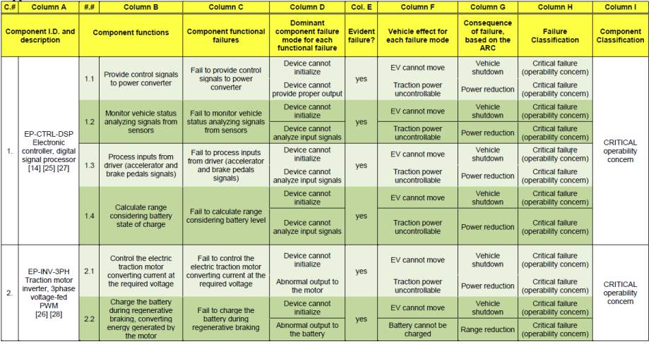
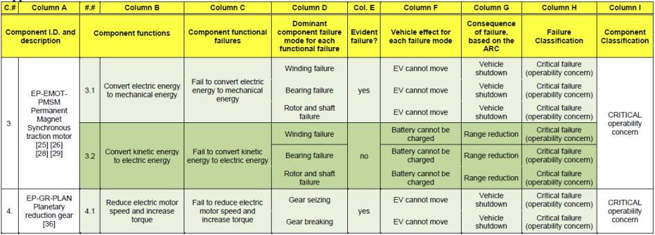
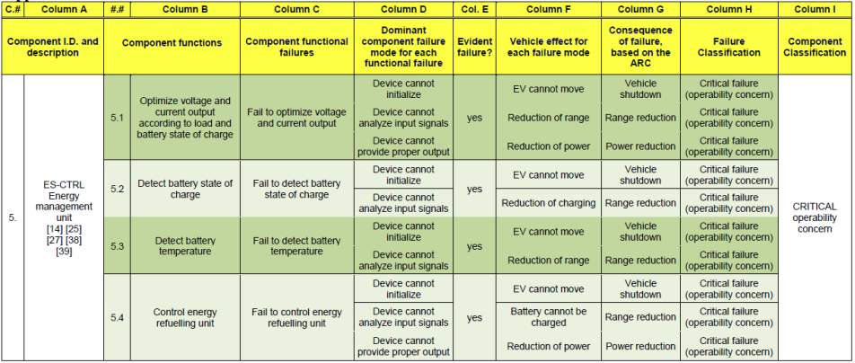
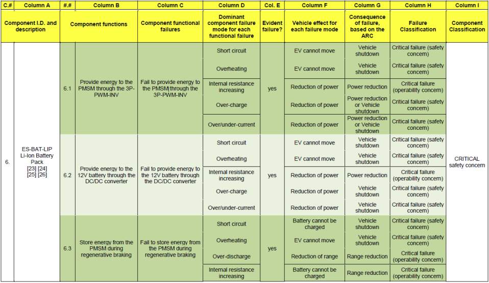
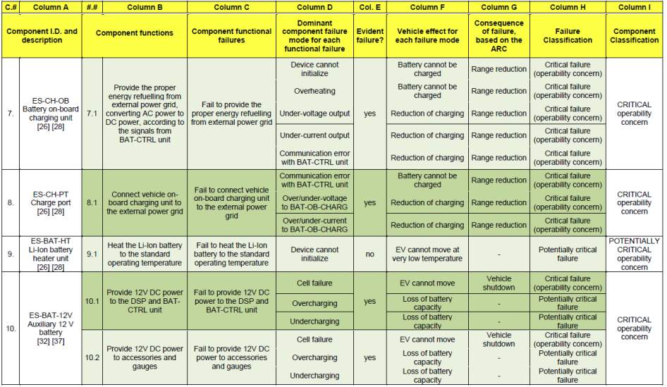
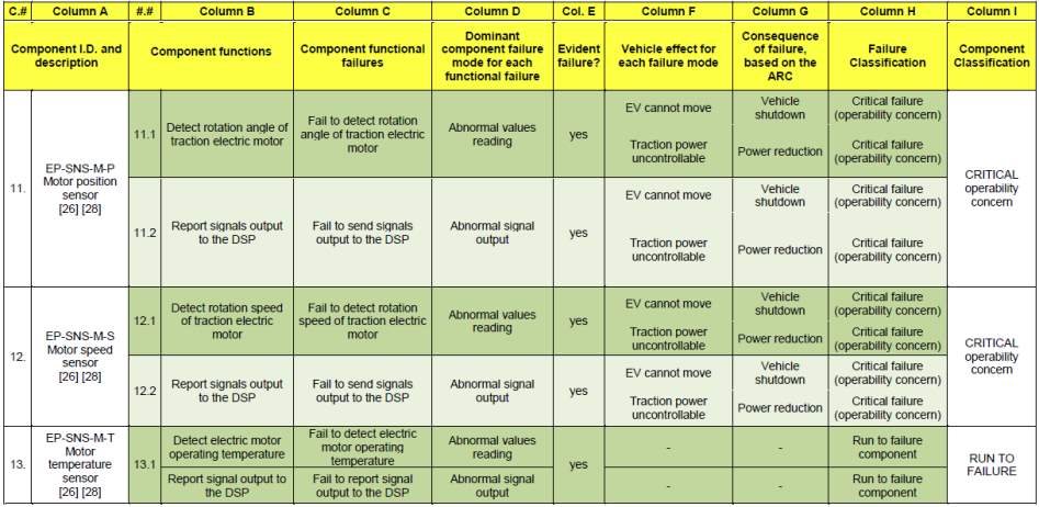
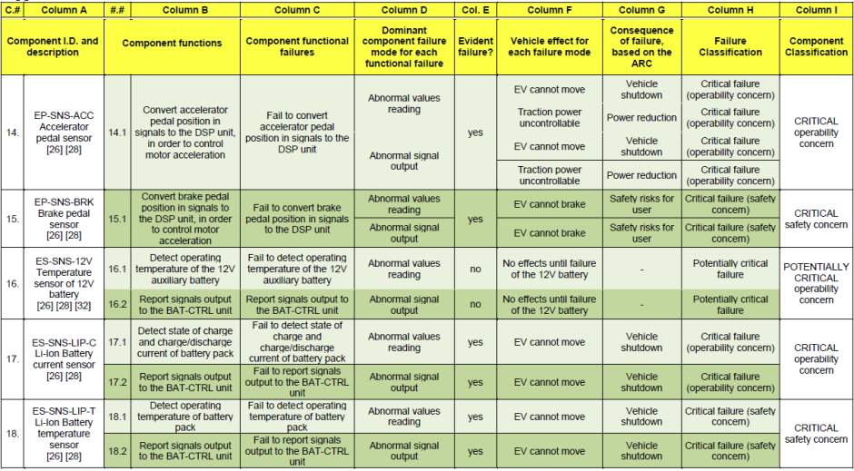
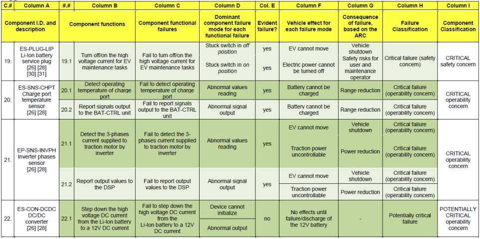
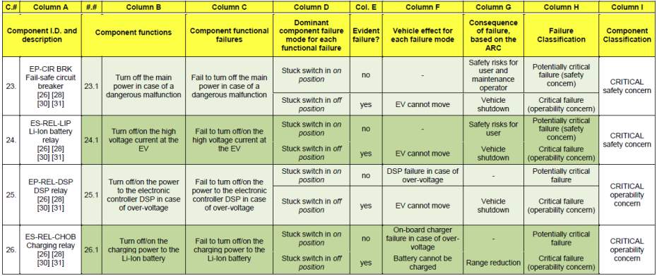
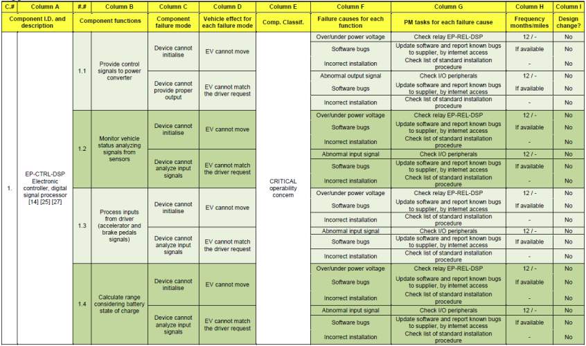

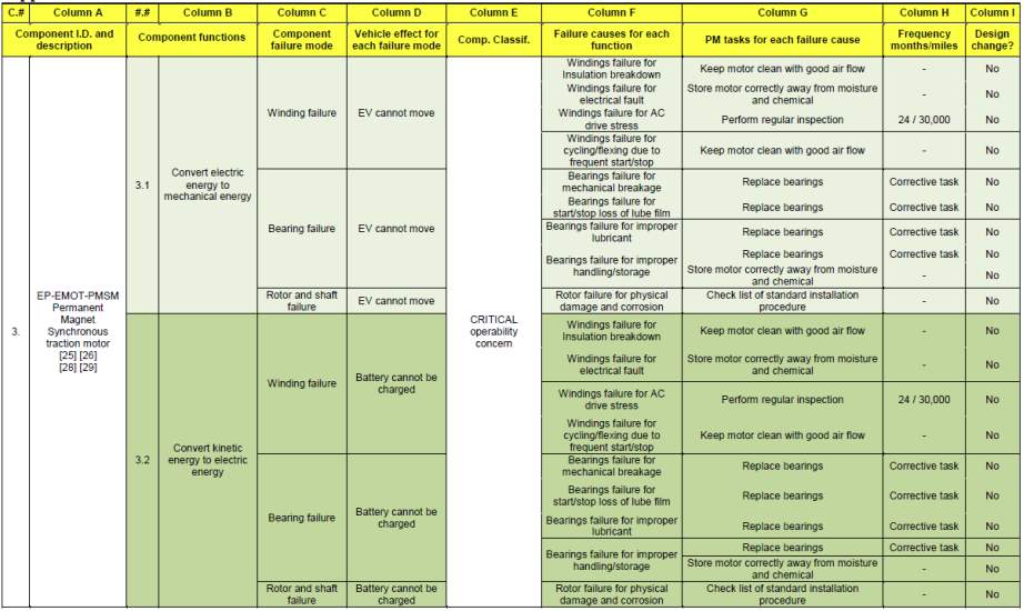
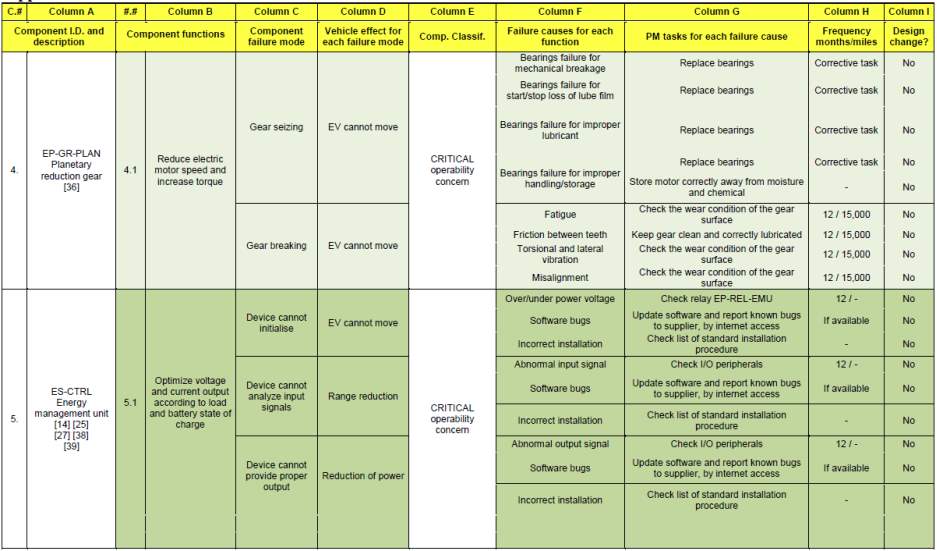
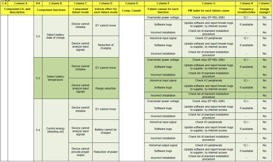
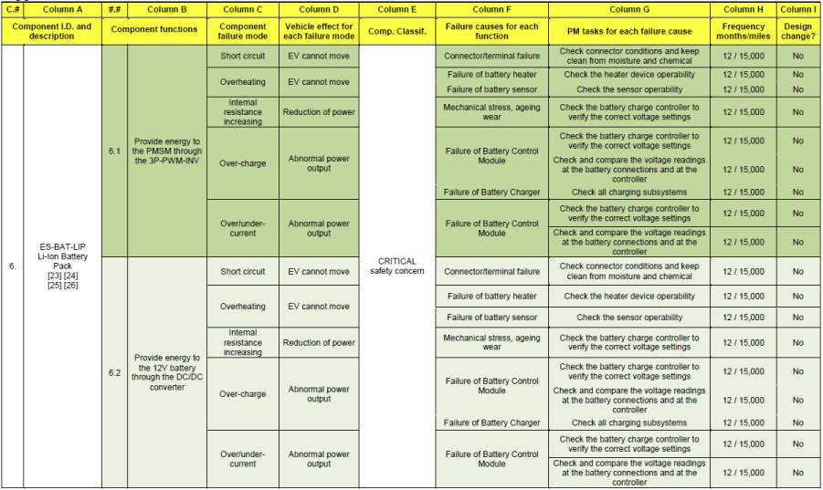
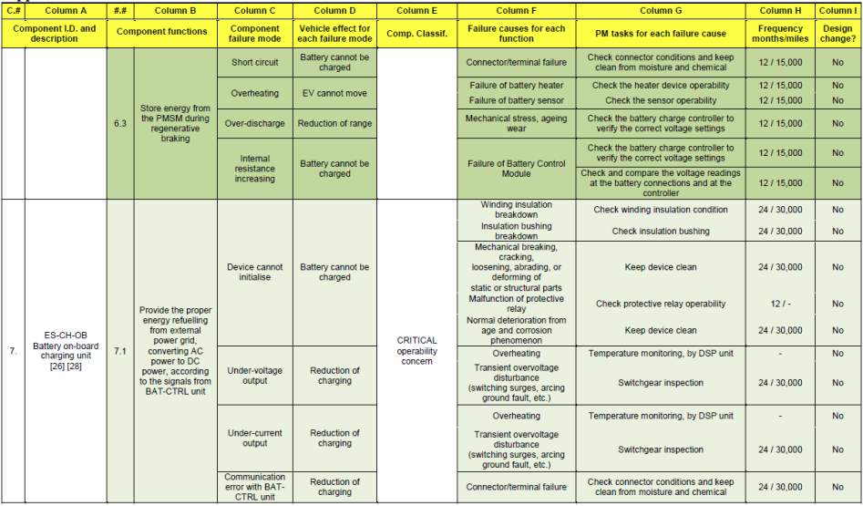
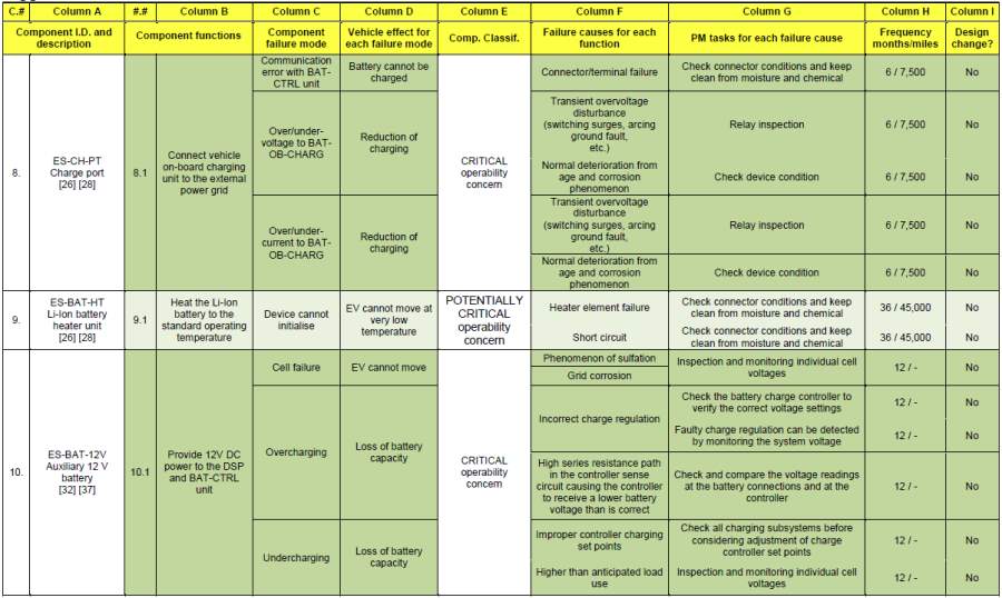
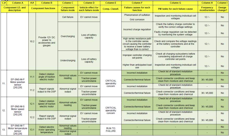
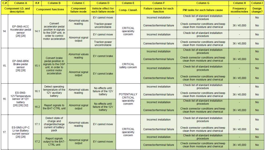
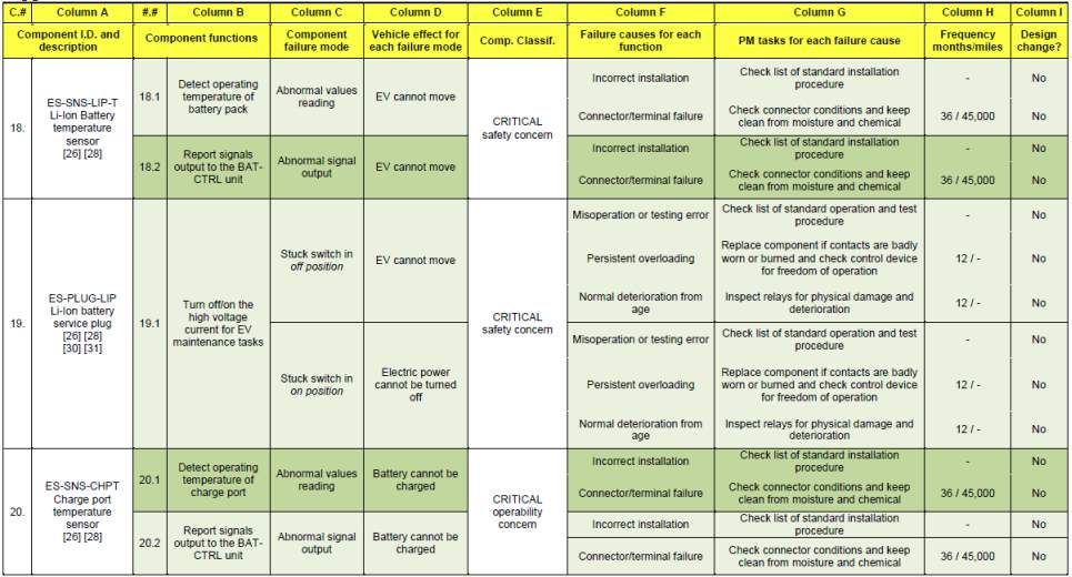
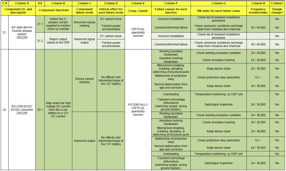
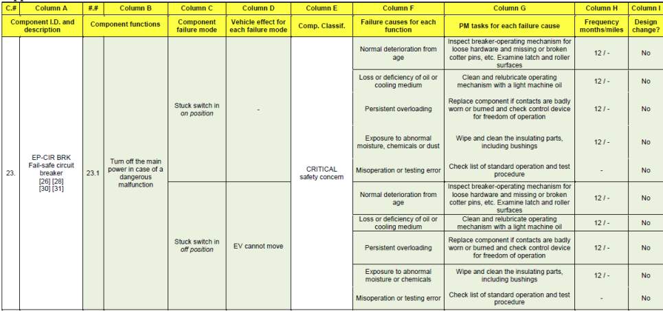
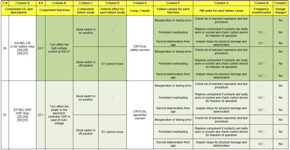
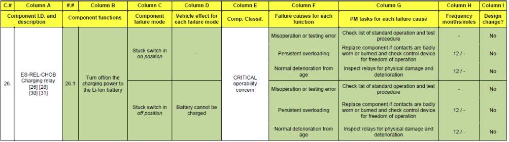
Cite This Work
To export a reference to this article please select a referencing stye below:
Related Services
View all


Related Content
All TagsContent relating to: "Business"
The term Business relates to commercial or industrial activities undertaken to realise a profit including producing or trading in products (goods or services). A general business studies degree could cover subjects such as accounting, finance, management and increasingly, entrepreneurship.
Related Articles

DMCA / Removal Request
If you are the original writer of this dissertation and no longer wish to have your work published on the UKDiss.com website then please: