Monitoring System Requirement of Lithium-based Battery
Info: 15909 words (64 pages) Dissertation
Published: 11th Dec 2019
Tagged: Energy
Abstract
This report contains a complete case study about monitoring system requirement of lithium-based battery, to ensure this highly powered technology is compile with Formula Student Car, and improve its performance.
J. M. (2016). Stated, that Lithium-based battery technologies provide performance advantages over the conventional battery technologies at high power density, long discharging time and low cost. The additional complexity of using this type of technologies increases the management difficulties for the accurate charging state prediction, life span prediction and cell balancing.
The common fact with conventional cars (relay on lead acid batteries) is the use of a battery to store electrical energy to start the engine, as well as partially supply the power to the electrical equipment of the vehicle.
It is important to control the temperature and charging voltage of lithium-based battery cells by considering a sufficient and well-designed cooling system.
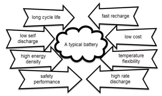
Table of content
Table of figures
Chapter 1
Introduction
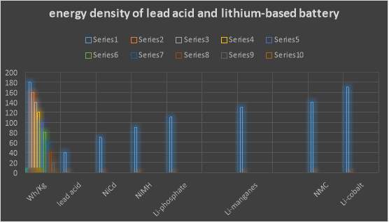
According to G. B. (2012). Lithium is the highest of all metal; it has the best electrochemical potential and provide the biggest particular energy per weight. Rechargeable batteries with lithium metal on the anode could give phenomenally high energy densities. The energy density of lithium-based battery is ordinary twice that of the standard Nikel-cadmium. Recently, lithium-based battery becomes the quickest development and most encouraging battery science.
While Lead, is a classified as very heavy metal thus, beside its highly cost producing, as well as recycling. The research took place for many years to improve battery’s performance and cost.
Then lithium-based batteries become the smart choice for almost all the devices and applications that relay on batteries as it provide the following
- Longer life cycle
- Faster recharging
- Lower cost
- Operate at a varying temperatures
- Higher energy density
- Lower self-discharge
- Higher rate discharge
- Safer as long as it maintained properly
Lithium is a very receptive and consequently unadulterated. It is difficult to find the Lithium in nature, Lithium metal is produced complex chemical procedure from lithium salts which are removed from mining, Zhi, L. (2013). Stated.
Overall lithium-based batteries have beneficial features that have made them the best choice in many application. According to Leker, J., & Winter, M. (2013). Lithium is the metal with both the lowest molar mass and the greatest electrochemical potential. This mean that lithium-based batteries can have high energy density. A usual lithium pack (lithium cobalt oxide-carbon) approximately is 3.6 V. and significantly their self-discharge is approximately 5% lower than NiCad batteries, notably its self-discharge at 20%. In addition these battery packs does not consist on those types of dangerous heavy metals (cadmium and lead). Finally lithium-based batteries do not have any memory effects and also do not need to be refilled with an electrolyte. This makes them lower maintaining comparing with lead-acid batteries.
Project background
The prime objective of formula student challenge, is to design and develop a comprehensive formula car that can take a part in the annual formula student challenge event. Notably this comprehensive design will be shared between all the engineering schools within the campus, which is allowing a group of student to work together as professional team, and share their knowledge to complete this project, and potential of winning this completion within the formula student rules.

To promote the design and increase the winning possibility, the campus formula car constantly subjected to technical improvement and additional features. As part of this improvement, the team decided to replace the conventional lead-acid battery with a modern technology (lithium-based battery).
This report, deliver a comprehensive case study about the characteristic of this battery, as well as it changing behaviour under different conditions to ensure it compile with this design, beside the practical work which consist on design and develop a monitoring system for this this battery, alongside apply this system to the battery under different conditions to ensure safe operation of this technology, by delivering a valuable parameters value to the driver and team members to improve the performance of the vehicle.
Monitoring battery system is very important feature. Since the essence of this feature is to detect whether the battery has enough energy to start the engine and deliver an appropriate power to car’s equipment, beside detect whether the alternator is sending a suitable energy to charge the battery, therefor this system can help to diagnose any faults within the cars electric system when occurs. Notably sending data about battery condition can determine the quality of the car performance, as well as it life cycle.
Project aim
This project aim is to study and analysis the electric system for the formula student vehicle, beside the lithium battery characteristic, to determine the changing behaviour of these technology parameters, and design the most suitable device to monitor this battery. Also, ensure the best performance and safe operation of this battery.
Project objective
- Investigate vehicle’s electric system
- Investigate lithium-based battery characteristic
- Investigate the targeted lithium-based battery parameters behaviour
- Investigate the most suitable method to monitor the lithium-based battery
- Design and build the monitoring device
- Test the circuit and ensure the safe operation in a different conditions
- Design a suitable layout for the design
Report Structure
The work structure of this report consist on five chapters as the follow
- Chapter two: provide literature review about the Lithium-based battery, and a comprehensive case study about the characteristic of this type of technology
- Chapter three: provide and a comprehensive case study about the charging system for the vehicles, as well as all it component technical issues
- Chapter four. Provide monitoring methods case study of the Lithium-based battery,
- Chapter four. contains the practical steps that followed to design and build the system
- Chapter five.
Contains testing the system and results, as well as discussion and conclusion.
Including the first chapter, that contain project aim, background and Gantt Chart.
Updated Gantt Chart & Milestones
| Project Gantt Chart & Milestones | |||||||||
| Work plan |
14/10/2016 |
10/11/2016 |
11/11/2016 |
15/01/2017 |
15/03/2017 |
20/04/2017 |
28/04/2017 |
03/05/2017 |
|
| 1 | Literature review of lithium battery |
Submit project planning |
Summit poster and report |
presentation and demonstration |
|||||
| 2 | Project plan | ||||||||
| 3 | Investigate vehicle’s electric system | ||||||||
| 4 | Simulate the design | ||||||||
| 5 | Design and build the device | ||||||||
| 6 | Poster and presentation | ||||||||
| 7 | Writing up the project report | ||||||||
Chapter 2
Lithium-based battery Literature Review
Introduction
This chapter contain, a comprehensive case study about Lithium-based battery, beside its characteristics. Also the changing behaviour of this technology under several conditions were discussed, as well as the technical facts that need to consider when dealing with this type of batteries.
Lithium-based battery
The chemist John Goodenough include his colleagues Phil Wiseman, Koichi Mizushima, and Phil Jones, were the first people to successfully produce practically valuable lithium-ion power packs, which their experiment took place in Oxford University in 1970s. After publishing their research in 1980, Sony firm turned this metal into a useful technology, who produced the first lithium-ion batteries in early 1990s. Since then they’ve become commonplace. Which has since become popular and kept its place as the best choice of rechargeable batteries, en.wikipedia.org stated.

Lithium-based battery characteristic
Bini, M. (2014) stated that, the fundamental of lithium-based battery functionality is consist on locomotion between negative and positive electrode. In principle such a system ought to work always, yet cycling hoisted temperature and longevity diminish it performance after some time. Fabricates adopts a preservationist strategy and determine Li-based battery longevity in most buyer items as being in the vicinity of 300 and 500 cycles of charging/discharging.
Assessing battery life on checking cycles is not indisputable in light of the fact that the depth of discharging may shift, and there are no obviously characterized benchmarks of what constitute a cycle.
According to García, R. E. (2015). A battery may flop inside the allocated time because of overwhelming use or unexpected temperature conditions; be that as it may, most batteries longevity are last significantly longer than the stamp shows.
Therefor the performance of a lithium-based battery is determined by the accompanying actualities
- A driving wellbeing pointer
- Battery’s capacity
- A leading health indicator
- The behaviour of battery’s Internal resistance
- Rate of elf-discharge
Remembering these certainties are less noteworthy in foreseeing the end of battery age with present day Li-based battery.
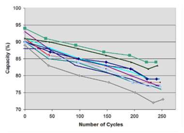
Figure (number), represent a cycled 11 Li-ion battery within codex research facility, when the capacity is decreasing. The 1,500m Ah pocket cells for Lithium-based battery were initially charged at a amperage of 1,500mA (1C) to 4.20V/cell, and as a step of the full charge saturation it permitted to saturate to 0.05C (75mA). After that the batteries discharged at 1,500mA to 3.0V/cell, and the cycle was renewed. As far as possible loss of Li-particle batteries was uniform over passed on 250 cycles, and the batteries work obviously.
//need to put figure number//
Sourced from: Choi еt аl. (2002)
Figure (1): eleven new Li-ion examined by codex analyser battery C7400. The initial capacity were approximately 88-99%, and after 250 discharging cycles.
Courtesy of Codex // maybe change title //
Despite the fact that a battery ought to convey 100% capacity amid the very first year of servicing, it is normal to experience lower then indicated capacity, and time span of usability may add to this misfortune. Moreover, producers have a tendency to exaggerate their batteries, realizing that not very many clients will do spot-checks and gripe assuming low. Opens the conduits for considerably more extensive execution acknowledgment. Cells with lower capacity may sneak past wrenches without the purchaser knowing, Ummartyotin, S., & Manuspiya, H. (2015). Stated.
Exceptionally indistinguishable to a mechanical gadget that malfunctioning speeder with substantial utilize, the depth of discharge (DOD), determine the cycle count of the battery. The litter the discharge, the more drawn out the battery will last. Fractional discharging on lithium-based battery is passable, it is highly recommended, not to fully discharge and charge the battery regularly between uses. Since there is no memory impact on this battery, it does not require a total cycles discharge. cycles as there is. The exemption might be an occasional calibration of fuel gauge on a modern battery technologies or devices. Cingolani, R, Scrosati, B. (2014). Stated.
Table (number), illustrate the variations of the depth of discharge level and the changing of the charging/ discharging cycles quantity of lithium-based battery before the capacity of that battery fall to 70%. Depth of discharge create a complete charge and discharge periodically to the showed rate levels in table. The varying parameters such as load currents, charging voltage and temperature are configured to the default voltage setting.
| Discharge cycles | Depth of discharge | Table 3
Li-ion life span according to |
| 300–500
1,200–1,500 2,000–2,500 3,750–4,700 |
100% DoD
50% DoD 25% DoD 10% DoD |
Sourced from: Choi еt аl. (2002)
Presenting the battery to high temperature and abiding in a full condition of charge for a broadened time can be more distressing than cycling.
The impact of extra charging the lithium-based battery is identical to when it works under high pressure, an atmosphere of 30-degree C is experimentally believed to be as elevated temperature, and so any voltage over 4.10 per cell is a high voltage.
The following table demonstrates the impact of temperature on a lithium-based battery and the state of charge.
| 40% charge | Temperature | 100% charge | Table 3:
Approximated battery’s capacity status after a year of storing within different level of temperature. High temperature causes quick permanent capacity loss. With Li-ion it has the same impact. |
| 98%
96% 85% 75% |
0°C
25°C 40°C 60°C |
94%
80% 65% 60% |
Sourced from: Choi еt аl. (2002)
In a lithium-based battery, every charging voltage of 0.1V, is represented in single peak reduction, which is twofold the cycle life. For instance, a lithium-based battery gives 300 to 500 life cycles, when it is charged to 4.20V per cell. Thus, a 600 to 1000 cycles are expected when the battery is charged to 4.10V per cycle. Therefore, the less the battery charging voltage, the longer cycles its provide.
As a basic rule, the overall battery’s capacity drops by10 percent occur when a reduction of 70mV charging voltage. Battery’s storage capacity reduces when the battery receives a low voltage peak.
Continuing lowering the charging voltage, may not increase additionally benefits, but rather conceivably actuate different. Most of the voltage-related stresses drive-out at this threshold, with respect to life span, the regular charge voltage is 3.92V/cell.
Table (number) summarizes the capacity as a function of charging levels. (voltage threshold experience deviation with high voltage energy).
| Charge level (V/cell) | Discharge cycles | Available stored energy | Table (number): Li-based battery life cycles as a function of discharging depth. the life span start to decrease at any voltage over 4.20V per cell. Life cycle increases a 0.10 V fall below 4.20V per cycle, with lessen capacity.
Guideline: capacity decrease by approximately 10% at every voltage reduction of 70Mv. |
| [4.30]
4.20 4.10 4.00 3.90 3.80 3.70 |
[150 – 250]
300 – 500 600 – 1,000 1,200 – 2,000 2,400 – 4,000 >4,000 |
~[114%]
100% ~86% ~72% ~60% ~40% ~30% |
Sourced from: Choi еt аl. (2002)
Table (nember) represents discharge cycles and capacity as function of charge voltage limit. Life cycle increases when a fall of 0.10 V fall below 4.20V per cycle, with lessen capacity. Charging voltage bellow 4.20V per cell increase battery’s life span.
For wellbeing reasons, numerous lithium-based batteries can’t surpass 4.20V/cell. Notably a high voltage boots capacity, surpassing the voltage abbreviates life span beside increase safety.
Figure (number) demonstrate battery’s cycle count in respect to charging voltage. Cycle count of standard lithium-based battery reduced by half at 4.35V.
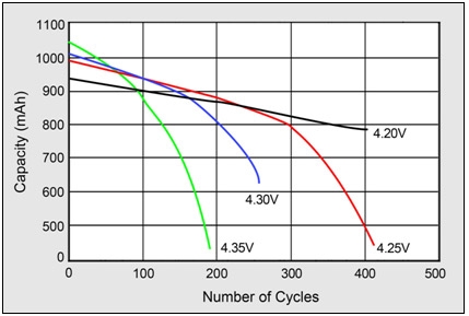 |
Figure 5: impact on cycle life at high charge voltages. Higher charge voltages increase capacity but decrease cycle life and compromises safety.
Source: Choi et al. (2002) |
| Sourced from: Choi еt аl. (2002) |
In some application, besides preventing applying a high voltage (over 4.20 per cell) for prolonged time, setting a suitable voltage threshold is required too. Otherwise the battery voltage becomes at natural level, as the battery charge stops the charging current.
Lithium-based battery challenges
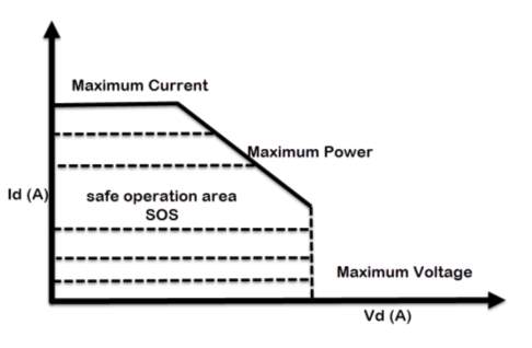
According to Miraoui, A. (2012). The most eminent essence that declares the performance of the lithium-based battery, are the operating temperature, current and voltage. Current, power and voltage must be maintained within the area indicated by Safe Operation Area (SOA) at all times, which represent under maximum voltage, current and temperature curve. The battery could be permanently defective if it is operated outside the safety zone. The batteries should not be charged such that its voltage exceeds its rated voltage or be discharged such that its voltage falls below the minimum recommended voltage.
The recommended upper limit of charging voltage for a lithium cell is 4.2V per pack. If this value is exceeded while charging, a high current will flow and causes in lithium plating and overheating. Not much from charging cycle, overly discharging the packs or storing them for long time would cause the packs voltage to drop below its lower limit, typically 2.5V, this could gradually break down the electrode.
How lithium-based battery works
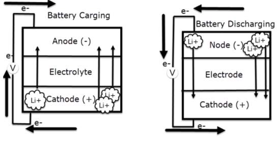
According to Huang, Q., Yang, J., Ng, C. B., Jia, C., & Wang, Q. (2016). All lithium-based batteries share the same working principles in comprehensively. During charging cycle, the positive electrode of lithium-cobalt oxide, loose some of its lithium ions, to the negative electrode through the electrolyte, graphite electrode and stored there. The battery store’s and deliver energy beyond this process. Notably during discharging cycle, the lithium ions pushed back to the positive electrode across the electrolyte, producing the energy that powers the battery. During charging and discharging cycles, electrons always flow in the opposite direction to the ions around the exterior circuit. Therefor the electrolyte forms an insulating barrier preventing the electrons to flow through it.
Remarkably the ions locomotion (through the electrolyte) and electrons (around the external circuit, in the opposite direction) are interconnected procedures, and is either stops so does the other. Lack in power is potentially occur when the battery is totally discharged, which is preventing the ions to routs through the electrolyte. Thus, electrons can’t move though the exterior circuit either. Similarly, when switching off the power that charge the battery, both ions and electrons stop flowing.
The battery essentially stops providing power at high rate, bearing in mind at low rate it keeps discharging, even when disconnecting the appliance.
Hassoun, J., Lee, K., Sun, Y., & Scrosati, B. (2011). Stated, that One of the lithium-based battery advantages, that it is not require any maintaining process within its life-cycle. No planned cycling is required, and there is no memory impact in the battery. Besides, the lithium-base battery is suitable choice for Formula Student Vehicle, since its self-discharge rate is not as much as half of the discharging rate of the lead-acid and NiMH batteries. Despite the advantages of lithium-based batteries, they also have few drawbacks. Capasso, C., & Veneri, O. (2014). Stated that, Lithium-based battery are brittle. In addition, it is very sensitive to amount of voltage and current that charging and discharging the battery, beside an extra attention to temperature that this battery face during it working time. To avoid any fault or failing status, a suitable device is required that detect any changes on those facts, and delivering a comprehensive data about battery conditions, to determine it performance. This technology, additionally alluded to as the Battery Management System (BMS), confines the peak voltage of every cell amid charging and keeps the cell voltage from dipping under threshold during discharging. Also the (BMS), controls the maximum charging and discharging currents and monitor the cell temperature, Huang, K., & Zhang, Q. (2012). Stated.
Advantages of lithium-ion batteries // add more here//
- Lithium-based batteries are more dependable than conventional technologies such as nickel-cadmium (NiCdn pronounced “nicad”).
- No memory impact on these technologies (where nicad batteries seem to wind up noticeably harder to charge unless they’re discharged completely first).
- Since lithium-ion batteries don’t contain cadmium (a toxic, heavy metal) they are additionally better for the environment.
- Lithium-based batteries are moderately light for the comparing to the energy they store.
Disadvantages of lithium-ion batteries
- Remembering that these disservices are adjusted by different points of interest, for example, more noteworthy lessen fuel consumption of electric and lower pollution.
- Safety issue, lithium-based batteries potentially catch fire when frequently overcharged or for any failure that causes a short circuit, which will elevate dangerously it temperature.
Technical facts need to be considered when dealing with lithium-based battery
- Besides cycling, the environmental conditions also, not cycling alone affect the life span lithium-ion batteries. The riskiest circumstance, is storing a fully charged battery at elevated temperature, which may make the battery detonate.
- The running-time progressively reduces in respect to the battery’s limitation capacity. Thus, battery packs do not defect abruptly.
- Battery’s life span increase with lower charging voltages.
- Lowering the charging voltage of normal car increases it life span when wired to AC grids. Using a monitoring device should satisfy a prolonged mode that hold battery’s voltage at 4.05V/cell as well as provide an approximation of 80 percent of the capacity is recommended for easy use.
- Remembering, that the plan point is to add charges to the battery just when its voltage drops to a specific point. Thus, when the battery fully charged, disconnect it from the power supply, Miraoui, A. (2012). Stated.
Diagnosing the battery
According to Arnold, C. B. (2013). Generally, battery and ignition circuit are the causes of starting problems when occur, in some cases, diagnosing the electrical problems is a complex issue, such as intermittent problem. Thus, during resolving electrical problems, some component is replaced unnecessarily due to the difficulty of diagnosing electrical issues.
Mainly, a low battery voltage is the cause of starting and drive ability problems, which is relay on a simple procedure to diagnose. The low battery voltage has several impact on the car electric system, for instance, low battery can case difficulty of starting and possibly misfire due to the insufficient current that the injectors receive. Also the impact of low voltage battery is significant on the fuel pump, by casing low fuel pressure, due to slow running fuel pump.
One of the disadvantages of lead-acid battery, when it fully discharged, a significant of chemical changing behaviour occur on lead plate located within the lead battery. A symptoms of low bower battery occur, due to the sulphate layer cover the lead plate that prevent the battery from charging. Therefore, keeping this battery at or near full charge at all the time is crucial.
Approximately, between four to five years is the average battery life in typical conditions. Battery’s power can be decreased up to 50% when the temperature dropped to 20 F degrees, notably the suitable current to start the cold engine is almost twice amps at this temperature. Thus, the impact of varying temperature on batteries is significant.
Ways of checking the battery
Kim, J. Y. (2012). There are many ways to determine battery’s conditions, the most accurate one, is using a digital voltmeter, that display battery parameters values as a digital number.
Battery’s voltage is no reliable to determine battery status accurately, as a fully charged battery is a most of the cars is approximately 12.65V. when discharging this battery to 75%, the readying display 12.45V. therefore the most accurate way to determine battery status is by measuring the battery’s energy.
Also, a fully charged battery may not be able to start the engine or even the battery may be defective, as the main concern when starting the engine, is that the battery can deliver a suitable current when applying a particular load on it.
Determine the battery status
According to Guo, X. (2015). There are two ways to determine battery status:
- To for accurate testing, it is recommended to fully charge the battery, than apply a particular load that consumes a particular amount of current (load testing), and measure battery’s current status using a suitable amps tester, notably this tester should calibrate the results in respect to the load changing as well as time.
- When the battery not fully charged, using an electronic tester (conductance), is recommended for extra accuracy
Technical fact when charging the battery
Recharging the battery externally or jump starting the engine with booster wires from alternative vehicle or any power sources, may run the engine once more, however it won’t be for long, as long as the charging circuit is not delivering typical voltage, Kim, J. Y. (2012). Stated.
Warning: never detach battery’s cables while the engine is running for any reasons (test alternator). The effect of that is harming the alternator and in addition different hardware segment, due to high voltage
Chapter 3
Car’s charging system literature review
Introduction
This chapter contain, a comprehensive case study about charging system for vehicle, beside its component. Also the changing behaviour of this circuit under several conditions were discussed, as well as the technical facts that need to consider when dealing with Lithium-based battery.
Vehicle’s charging circuit
Meng, K. (2014). Stated that, the electrical system of a car is a classified as closed loop circuit with a separated power source which is the battery. Notably this battery operate on a sort duration within this circuit that is will stops as soon as the engine cranked.
The current will flow from the battery along a particular cable to the starter after turning the switch on. When the engine is running, the battery and the all other car’s electric system will be powered by the engine. Otherwise when it is off, the battery will proceed with powering this system. Thus, connecting car’s body to the earth is required, which is can be done by connecting it with battery’s negative terminal with suitable cable.
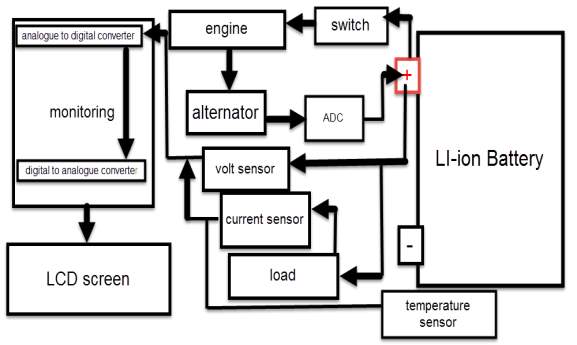
According to Kupzog, F. (2013). The car’s electric system consist on four main circuits.
- Starting circuit, where the battery supply current to the starter when turning the switch on, and the starter amplify this current to make it suitable for spark plugs to start the engine.
- Charging circuit, where the engine crank the alternator, that induce current through electromagnetic procedure, and deliver this current back to charge the battery after rectifying it (converting from AC to DC), and regulated since the current value will vary due to engine speed variations.
- Powering loads circuit, where the battery and/or the alternator supply power to car’s electric equipment.
- Monitoring circuit, where a monitoring is detecting battery’s parameters to determine it status.
Car charging system component
| Switch | Ignition | Battery | Starter | Alternator |
| Engine | Spark Plugs | BMSs | Wiring Loom | Fuses |
Electric circuit that powered by the battery when the engine is off, and power by the alternator when the engine is on
| Heated rear window | Fuse box | Sensors | Gauges |
| Windscreen-wiper motor | Indicator | Electric fan | washer pump |
| Electrically operate radio aerial | Headlamp | Distributor | Heater |
| Electrical instrument | Magnetically operated locks | CD player | Electric motors |
The above circuits are generally operating by switch or relays, to active the circuits or open them.
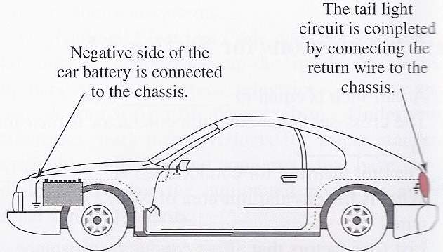
Earth-return system
According to Kim, D. (2012). When powering a particular electric equipment that connected to the battery, the current delivered from the battery’s positive terminal (+) to that equipment. Notably the other side of this equipment is earthed to car’s bode, which connected to the battery’s negative terminal (-).
When the negative side of this equipment connected to the car body, which earthed by the battery negative terminal, it is called earth-return circuit.
The current strength is determined in amperes (amps); the pressure that causing it to flow around the circuit is called voltage (volts). Wright, N. (2016). Stated, in the late cars, the battery voltage is approximately 12volt. Beside it the battery’s capacity is determined in amp/hours. A 50 amp/hour battery should be able to deliver a current of 1 amp for 50 hours, or 2 amps for 25 hours.
When battery voltage fall, the flowing current strength will decrease. Thus, due to the lack of power it prevent the electric equipment from working.
When the electric current flows within a wire, it face a particular resistance from this wire, this gauge of resistance is determined in ohms.
Since thin wire has more resistance than thick once, beside, that thick wires has more place for the electrons to move through, thus, the conductance of the thick wires is greater than the thin once.
Notably the resistance that current facing during it flowing cycle is transmitted to heat.
This can be useful, for instance in the very thin string of a light bulb, which glows white hot. Thus, a thin wire is the most suitable connecting choice for those equipment that relay on high current consumption. Otherwise the alternative choice will cause turn the fuse to be defective or blow it, due to the overheated wire. Significantly the determination of the electrical units engaged: for instance a pressure of 5 volt cause a current of 5 amp to flow through a resistance of 5 ohms.
For ohm’s law, amp is equal volts over resistance. I =
VR, for instance the current consumption for a bulb with a resistance of 5 ohms, and 10 volts pressure is equal to 2 amps.
Therefor the thickness of wire connected with this bulb must be suitable to handle 5 amps without any problems.
To determine the power consumption of this blub, simply is multiply the current by the voltage which measured in watts. In this case the bulb consumption is 20watts.
Positive and negative polarity
According to Robertson, S. (2001). Current flowing in a single direction from the battery, when a component connected in wrong way, the component will not work as the current flowing into it from the earthed side, possible causes defection.
Therefor the battery power the system through it positive terminal (+), notably the negative one (-) is earthed to the ear-thing point.
Short circuits and fuses
A short circuit occurs for many reasons, the most common one that, using wrong thickness of wires, as well as wires different wires touching each other. The impact of the short circuit incidence is the resistance of the component will be bypassed, which causes damaging the wire and possibly catch a fire, due to high flowing current.
Fuse box
Usually fuses are combined together within a water and heatproof box, that siled properly to be protected from any external affect. The aim of these fuses is to protect the component from over-flowing current, as well as any defective problems, as they consist on a short length wire, that will prevent the current from flowing, when it disconnected by the cause of high amps current, Lawes, J. (2006).
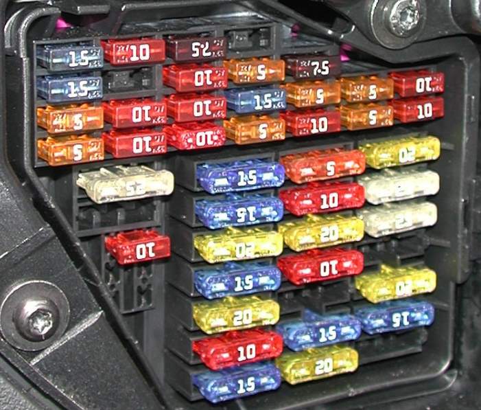
Thus, the best fuse type are those with short-thin wires. Therefor these fuses provide a big benefit that, protect the system component and reducing the cost of replacing equipment when short circuit is occur.
Notably it is highly recommended to install an individual fuse for each component, which allow those component to work independently, when a short circuit occur, other component won’t be affected. Also those fuses are earthed on the other side by fuse box ground point.
Circuit types
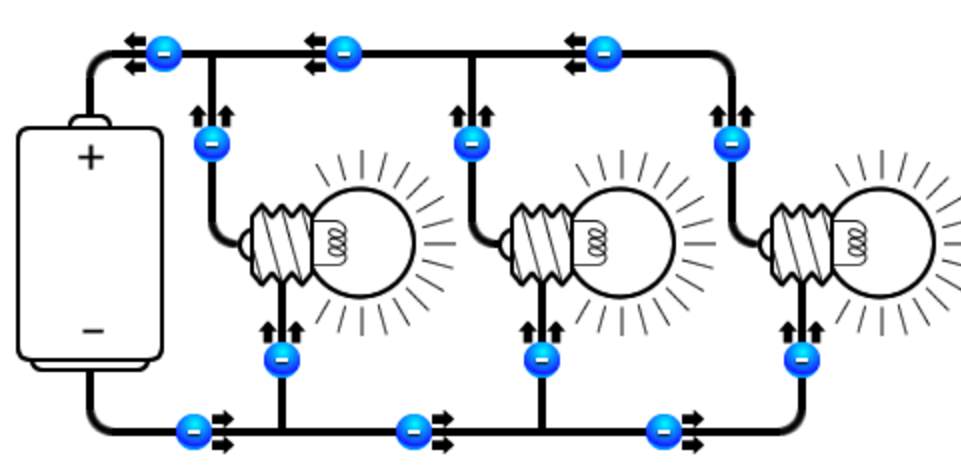
According to Williams, T. (1991). Mainly there are two different type of circuits that used in electric system
- Parallel circuit, where the component connected beside each other, thus, they share the same amount of power.
- Series circuit, where followed by the other within same line connection, thus the power they receive is different.
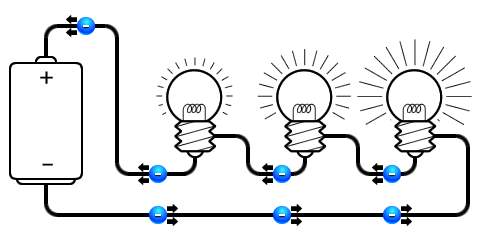
In la amp application, the glowing factor occur when a particular amount of current consumed by it resistance, which depends of the value of this resistance.
So when two resistors connected in series, the resistance that current face will increase, causes decreasing in lamp glowing density. Notably in a parallel type, the number of resistance has no impact of the glowing lamp density.
An example of the series connection within car’s electric system, is fuel level sensor that deliver an electric signal the fuel gauge, due to the variation of its resistance is depend on the fuel level within the tank
Ancillary circuits
According to Heisler, H. (1999). Battery connected to the starter with an independent cable, and the starter with ignition beside the spark plugs form the circuit that turn the engine on by the high-tension current amplified within the ignition, due to the electromagnetic process, and, delivered to the spark-pugs that fire the engine.
Once the engine start running, it crank the alternator, which induces and alternating current that converted to DC current to charge the battery. The insularity circuits are those connected to the ignition, which is mean they depend on the ignition to be active. The benefit of this type of circuit, is protecting the battery from total discharge when switching on some electric equipment. Notably some other circuit who consume low current, most be wired independently from the battery, like front and back light, allowing them to work even when the engine is off. While other circuitries who consume high current, are usually connected to the ignition circuit.
In additional some other equipment that wired to the ignition circuit, can work without turning the engine on, by turning the starting switch to auxiliary position.
Wires and printed circuits
In this type of circuit, wires and cable size, declares the maximum acceptable current that key can handle, and the instrument connection located at the sides of these circuit are subjected to fraction the integral catches. Thus, a combination of many electric cables and wires installed within the car. The solution of not misconnect these wires are to colour code them, Denton, T. (1995).
To make this cable installation organised and tidy, attaching all cables that goes in the same directions within isolated bundles. The entire bundles and wires known as wiring loom. That covers all around cars body.
Alternator checks
According to Heisler, H. (1999). The alternator charging output increments in corresponding to the electrical load on the charging system and motor speed. The voltage regulator that control the charging current generated by the alternator, is usually located within near by the alternator (internal regulated), or in some cases, it located in some place under car’s bonnet (external regulated). In the late models cars, the charging output is regulated by the powertrain control module (PCM). Alternator may become defective, due to the extra heats caused by overloading the alternator. Thus, the impact of defective alternator is significant on the battery, as it prevent it from recharging, and it becomes flat.
There are many symptoms of charging problems such as
- Dim headlights
- Hard starting
- Charging system warning light
Eventually bench testing an alternator is a good way to verify the diagnosis and/or to confirm the output of the alternator.
Starter checks
A defective starter may prevent the engine from staring, there are some failures symptoms, which that indicates the defective starter
- Switch circuit issues of the ignition
- Safety brake or/and neutral/park switch circuit
- Immobilizer system anti-theft issues
- Failure solenoid of starter drive
As long as the battery is fully charged, and it is capable to deliver enough power to the starter, but the engine is facing difficulties to turn on, or not starting, this symptom indicate that the starter is a defective and may need to be fixed or replaced, According to Heisler, H. (1999).
The most common cause of the starter failure is the following
- worn starter drive, Brushes and bushings, due to long term of usage.
- Defective starter solenoid, a defective starter solenoid prevents the starter from firing the engine. Since the solenoid receives an electric current from the battery when the switch turned on, and pass it to the engine.
- Overheated engine, occurs when Prolong cranking.
- A defective mechanism that engage the flywheel with the starter drive, can also affect the starter.
Starter technical fact
It is crucial to consider matching, the electrical connections, as well as the bolt pattern of newly installed starter with the original once, beside number of teeth within the drive gear. I additional some other component may also be replaced, such as engine ground straps and battery’s cables. It is recommended to attach a suitable material to the starter when replacing it, for extra protection if the starter drops According to Heisler, H. (1999).
Ignition diagnosis
The status and performance of the ignition system, can be determined by the ignition patterns, thus, reading those patterns on a scope is a recommended procedure to declare the ignition status, According to Heisler, H. (1999).
Spark plugs diagnosis
A defective or worn spark plugs can cause poor performance and also starting problems, as the impact for defective plugs is damaging the catalytic converter due to low power. In additional it may also have impact on the exhaust hydrocarbon emission as well as economy issues.
Spark plugs wear out after (100,000-mile), and reasons of failure, is that the carbon deposits block the electric routs.
Spark plugs wires diagnosis
The ignition cables or the spark plugs wires deliver a very high voltage from the distributor or the ignition coil to the spark plugs.
Significantly plug wires can deteriorate with the following facts
- Defective plugs
- Starting problems
- weak performance
When the terminals or boots are loose, cracked or wear out, indicate that the plugs wires should be replaced, According to Heisler, H. (1999). May also consider the following conditions
- If the wires are cracked.
- The internal resistance of the wires exceeds specifications.
- Sparking.
In late cars models, the spark plugs are connected directly to the coil, for extra efficiency and reducing failure possibilities, as there are no wires required between them. In some cases, it is difficult to diagnose the ignition with scope, thus, a special adapter is required to the electric signal that generated or amplified by the coil.
Ignition coils diagnosis
Coils occasionally flop, when occurs, spark plugs don’t not receive suitable to fire the engine.
Ignition coil types
- Single-coil ignition system, a defective coil stalls the engine and won’t start again.
- Multi-coil ignition system, a misfire occurs on the cylinder that relay on the defective coils only.
When the coils internal resistance not matching the data sheet, it indicates that the coil is defective. To determine the status of the coil, an ohm meter is used to measure the internal resistance.
Ignition module diagnosis
Therefor loss of spark indicates that the ignition module is defective, or that it is losing its trigger signal from the crank sensor.
The module approaches the end of his life span, when the ignition receives a suitable power, enable to amplify it, According to Heisler, H. (1999).
Alternator charging output
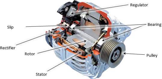
According to According to Heisler, H. (1999). The alternator is the heart of the charging framework. It convey an appropriate energy to completely charge the battery, thus other electrical circuits when the motor is running. The alternator is mounted on the motor and is belt-driven off the crankshaft pulley by a serpentine belt or v-belt.
The alternator is the heart of the charging circuitry, as It deliver power needed to fully charge the battery, and so other electrical circuits when the engine is running. The alternator is located on side of the engine, and is belt-driven off the crankshaft roller by an over-elaborate belt (v-belt).
Two crucial stages for alternator to charge the battery
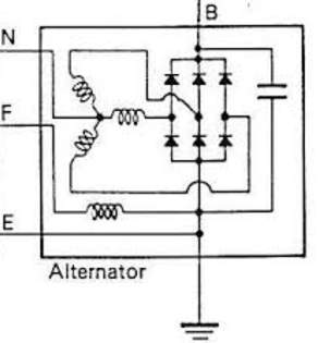
- Rectifier stage
Three positive diodes control the positive side of the air conditioner sine wave, while three negative diodes control the negative side.
The alternator produces exchanging current (alternating AC), which is changed over to direct current (DC) by diodes rectifier in an independent circuitry, which is usually located or attached to the alternator body.
Diodes passes only current in a one direction, which how they change over alternating amperage to DC, According to Heisler, H. (1999).
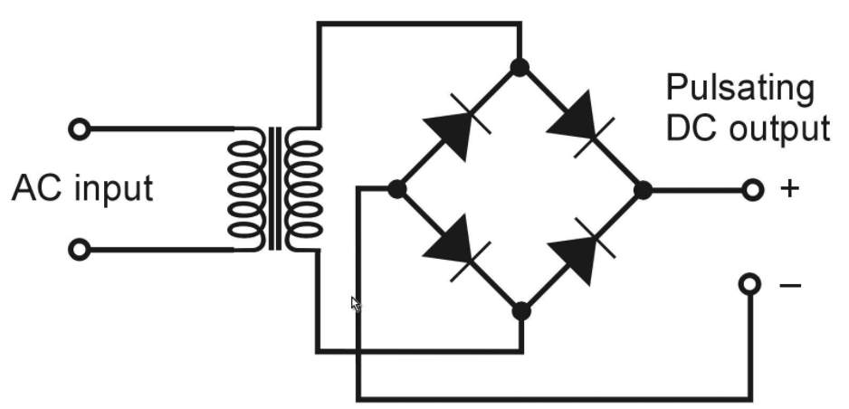
The sine wave of the AC is controlled by the positive diodes, beside the negative diodes control the opposite side.
Increasing the engine rotation and/or increasing in load consumption, increase the alternator charging output. The high revolution per minute (RPM) the more output delivered to the battery and load.
- Alternator voltage regulator
According to According to Heisler, H. (1999). The output of the alternator is varying with engine speed, at high speed, a high voltage expected to reach to the battery. Since batteries has maximum charging voltage limit.
Thus, keeping this output within acceptable range is crucial, which is can done by the voltage stabilizer (regulator). Commonly, this device is located within the alternator pack.
- On late model vehicles, the alternator output regulated by the power train control module (PCM).
- On conventional vehicles, alternator output controlled via electro-mechanical device that consist on magnetic contacts to stabilize the voltage.
Since 1980s, most voltage controllers are provided as solid-state circuits that relay on transistors.
The actual generated voltage will vary depending on engine rotations speed, temperature and vehicle’s load, in all cases it is higher then what battery can handle. At normal conditions, the output is approximately 13.9 to 14.4 volts without any current consumption. The following facts effect the battery charging status
- Temperature
- engine RPM
- type of battery
- battery’s state of charge //put figure number, see figure…//
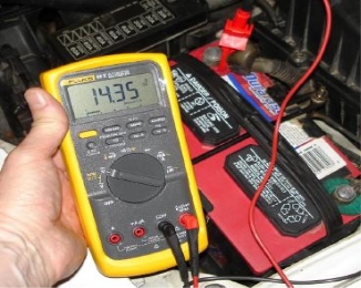 |
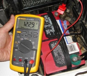 |
The left photo above shows regular alternator output voltage when engine is running and the vehicle is stationary. The above photo at the right lower alternator output voltage when it worn. A low reading indicates the charging system is not generating enough voltage to charge the battery.
Measuring alternator outputs, Denton, T. (2011). Stated the following
- Alternator voltage
The variation of the factors (temperature, battery state of charge, load value and the engine speed) are proportional to the variation of the generated output from the alternator. at low temperature, the charging output is more efficient.
- Alternator amperage output
Alternator electrical current, is that amperage generated by alternator at particular aped and voltage. Most late model alternator delivers about 110 to 160 amps or more.
The higher engine speed, the higher current output generated.
Inductive amp, can be used to measure alternator amperage output. Which is represented in Watts (amps times volts).
Alternators failures
- Alternator overheating
Since the alternator located near the engine under the bonnet, the temperature of the alternator is increasing, alongside high electrical loads create even more heat. To reduce the heat, alternator associated with an internal and /external fan that pulls the housing to reduces the stator and rotor temperature.
Therefor if the alternator is working hard under a heavy load at low RPM, there may not be enough cooling to prevent the unit from overheating. The alternator becomes defective by damaging the windings and/or wiring connections within the unit, due to the excessive heat. This has a tendency to be a greater amount of issue on vehicles where the area of the alternator confines wind stream and cooling, Denton, T. (2011).
- poor alternator wiring connections
The alternator may experience working under high pressure if battery cables are not connected properly. A poor connection causes a voltage drop across the connection, due to increasing of the resistance. This, in turn, generate resistance for the flowing current within the charging circuit.
Therefore, the rout of the lowing current within the charging system, is starts from the alternator toward the battery, then to the rest of the electric equipment within the vehicle, which all are connected in series, Denton, T. (2011).
- Alternator diode failures
One the most widely recognized reasons for charging issues is the defective of at least one diodes within the alternator (rectifier circuit). At the point when motor is running, electric current moves through the diode trio cross the battery, and returns back to the alternator.
The diode trio deliver a voltage to the indicator light ground side During charging cycle. The battery offset voltage approach positive side of the warning light, once the engine turned on, the light glows. Charging system warning light turns on, when the flow from the positive side of light circuitry, which usually occur when the alternator not charging, Denton, T. (2011).
If one of the diodes fails, it may cause the charging system indicator to glow dimly. If more diodes fail, the light becomes higher. The alternator decreases it amperage, due to the retuning current from trio. The more defective diodes, the lower alternator output.
Alternator tests
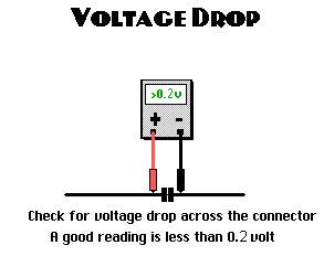
Alternator circuit voltage drop tests
While the engine is running and the vehicle is stationary, connect the red wire of the voltmeter to the battery positive (+) terminal, and the other to the battery negative (-) terminal. In a normal condition, an approximation of 0.2V expected to be displayed on the voltmeter, Denton, T. (2011).
Extra facts that affect alternator performance
Alternator vibration
Loose alternator mounting bolts and can cause vibration which may damage the alternator. Also the vibration can indicate a defective belt tensioner if the alternator bearing or diode is defective, which lead the current to flow to the opposite direction a cycling buzzing noise may occurs.
Conductance testers
Conductance tester determine the active volume plate area that available to store and deliver power, by sending a particular frequency signal though this battery. Bearing in mind that battery conductance decline, as battery ages.
Measuring conductance is a relatable method to dive an accurate result about battery conditions, bearing in mind that some factors can affect the conductance, such as sorts, opens or other defects issues
It is possible to estimate battery’s longevity by measuring the capacity of battery’s cold cranking (CCA), which can be done, using the electronic battery testers.
In additional, these testers can determine the output of the charging system with a load, when the engine is running, as well as measuring the consumed current.
Therefor if the battery’s cold cranking rate is identical or higher than the original manufactured battery’s equipment, it indicates that the battery is defective, and require replacing.
Therefor if the vehicle needs a new battery, it should have the same or higher CCA rating as the original equipment battery specified by the vehicle manufacturer.
Technically it is recommended to fully charge the battery before placing it in car. Besides that, the following equipment should be always checked
- Clamps
- anti-corrosion washers (for battery terminal)
- Battery cables
- Battery tray and/or battery hold-down hardware
Chapter 4 simulation
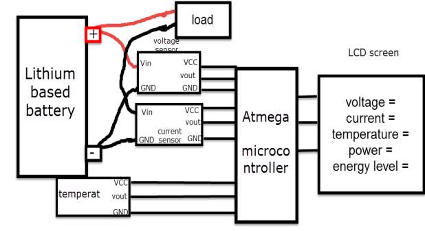
It is recommended to simulate the design before stating building it, using one of the software engineering in this case (MATLAB software). By following this process, the cost of the design decrease, regarding the potential of observing the device output and modify the design when it need. The battery degradation model consist on two batteries (battery A under temperature effect, and battery B without temperature effect), beside voltage, current and temperature sensors. The sensors detect battery A and B, and display their responses continuously. Also a temperature source is considered.
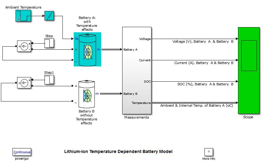
The model parameters were predominantly achieved in terms of Lithium-based battery characteristics.
The influencing factors that affect this model is significant.
Factors that affect the Lithium-based battery model
- Environment temperature
- Current consumption
- Charging voltage
- Discharging time
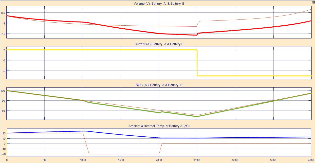
The model simulation experiment, prove that increasing the charging voltage of the Lithium-based battery and the discharging current, resulting increasing the battery temperature
Notably, when the battery under high temperature effect, the battery output becomes poor, also it reduces its life span. Bearing in mind that those factors are varying, which can are can determined hose factors are
Chapter 5
Monitoring lithium battery literature review
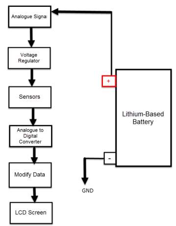
The simplest method of monitoring batteries is using analogue circuit, notably these type of circuits consist only on an analogue component connected together within a soldering board. Bearing in mind these conventional type of monitoring are very simple, and not efficient as it will only display a clue of light glowing or for instance just a relay stopping action, when amount of voltage is exceeded, Sauer, D. U. (2014).
Since the lithium battery is very sensitive to the temperature and the amount of volts and current, lead to significant demand of displaying the aimed battery parameters status in very accurate way, (display the detected parameters as a digital data within LCD screen). Therefor the best suitable engineering monitoring method for this case is using microcontroller (MCU).
Microcontroller is a smart electronic chip that contains many electronics component, those component are forming together an integrated smart circuit (small computer), as it contains CPUs (processor cores) alongside a programmable pins (input/output) as well as memory. The functionality of these type of circuits depends on two main parts, a hardware part, and software part (using a code written in an engineering language to control this circuit). Notably these smart circuit are very efficient and modern technology, the first microcontroller were launched in 1970s by Intel 4004 as a 4-bits chip, now days there are a much more flexible chips that provided with much more bits that suite life development demand. Almost all of the devices and machines that produced in the last 30 years are depends on these smart chips, Qiao, W. (2015).
Comparison between the raspberry pi and Arduino
Raspberry pi
The raspberry pi is a very cheap flex able computing platform, mainly used to run multiple tasks in the same time, which can one by programing its digital pins with a high level engineering language.

Arduino
According to John M. (Systems engineer). (2016). Arduino Is a simple microcontroller that can run one particular program the time, and repeating running the programme over and over as long as the condition is valid. By programing it through it analogue and digital pins, using one of embedded programming language.
Since the signal that the sensors reads for the battery are analogue, and the computer does not recognise analogue signals, therefor raspberry pi is not suitable for this design, as it is not contains any analogue pins to read. Significantly the Arduino does have analogue and digital pins, which making the best choice for this design.
Principle of sensors operation
Input impedance According to Peng, H. (2016). DC voltage gauged by a digital multimeter, if the input impedance reading is 10MΩ or more, it indicate that there is at least 10 MΩ resistance between the two multimeter tests.
Detecting the voltage across a component within a circuit using multimeter with an input impedance of 10M ohms, is identical to connecting a 10M ohm resistor across the component.
If a voltmeter has a low input impedance, for instance 5KΩ and a voltage across a 5KΩ resistor is being measured, the multimeter is effectively changing the resistor value to 2.5 KΩ (two 5 KΩ resistors in parallel = 2.5K resistor). The multimeter, therefore, has changed the circuit and possibly the voltage being measured.
So an elevated input impedance is suitable in this voltage divider circuit when the impedance of this voltmeter has an effect on the circuit being measured. Therefore, an elevated input impedance device will generally be affected with noise or interference (EMI) comparing with a low input impedance device, John M. (Systems engineer). (2016).
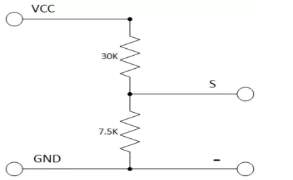
Voltage divider circuit
Peng, H. (2016). Stated, that a usual voltage divider circuit depend on two resistors connected in series, according to ohm’s law, this circuitry will reduce the voltage to suit the Arduino analogue input.
The circuit shown will divide the input voltage by 11(from the battery as the example input voltage being measured). The circuit with the particular values shown has an input impedance of
110MΩ + 100KΩ = 1.1 MΩ
and it is suitable for measuring DC voltage up to about 50V.
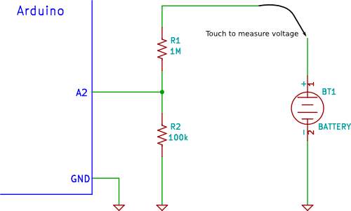
Arduino voltage divider
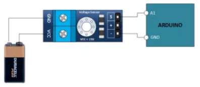
It is possible that the sensors to share the ground pin with Arduino GND pin when Arduino powered exterior power supply (battery power).
Input protection
When detecting a low voltage in the circuit diagram above, for instance 5V, 9V or 12V, the selected resistors value of the voltage divider circuitry protect the circuitry from any over-voltage.so for instance if a high voltage of 40V is detected, the Arduino remains safe.
Arduino data sheet indicate that it possibly be defective if the voltage reaches 55V and higher. Therefor the principle of the resistors network that form a voltage divider, is identical to input voltage divider of 11V, so when dividing the maximum voltage over the input voltage divider gives the appropriate Arduino typical voltage,
55/11 = 5V.
So in summery measuring 55V, the Arduino detect this value as a 5V.
Understanding and using this fundamental of voltage divider, is to avoid using sensors to detect the aimed battery parameters (voltage, current and temperature).
Notably it is exactly the same principle that those sensor are using, but for more accuracy the manufactured sensors are preferred in this design, Ho, M. (2016).
Calibrating the Arduino and the circuit
Using a maximum of 1% tolerance resistance, and precise voltage reference for the Arduino is crucial for high accurate reading, since the application that going to apply to (Lithium-ion) is very sensitive to any changes on these readings.
In fact there is another to achieve a high accuracy reading, is by calibrate the circuitry. The calibration can be done within the Arduino sketch code, after reading the actual value of Arduino reference voltage and the actual reading the voltage divider circuitry.
Method used for this design
This design consist on two parts
Hardware part
Based on the study of the lithium battery characteristic within this report, the major parameters of the battery that need to be monitored are the following
- Voltage
- Current
- Temperature
- Power consumption
- Battery level (energy percentage)
Sensors and chip, needed for this design
| Component | Type |
| Volte sensor | B25 |
| Current sensor | AC2712. Up to 30 amps |
| Temperature sensor | LM |
| microcontroller
2 ×Voltage stabilizer |
ATmega.328
LM217 |
| Clock crystal
|
16 MHz |
| Potentiometer | 100K |
| Capacitors | 2
×22 pF / 2 ×0.33mF |
| Resistors | 1
×1k / 1 ×10k |
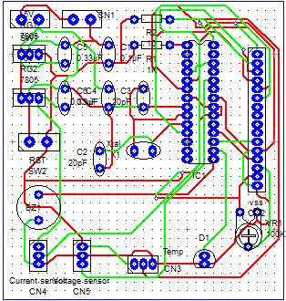
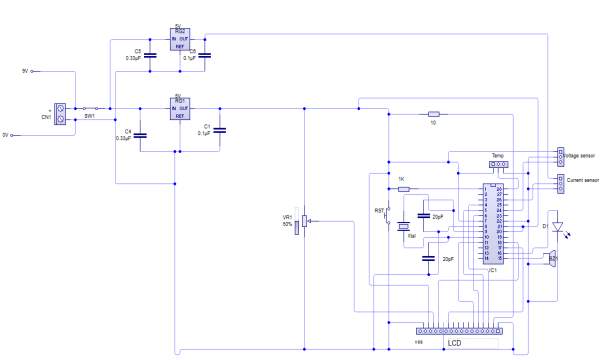
Build the circuit
Using PCB software
Using live wire software
Detecting battery’s voltage, current and temperature
According to Peng, H. (2016). Arduino analogue inputs can be used to measure DC voltage between 0 to 5V (on Arduino such as the Arduino Uno when using the standard 5V analogue reference voltage). The range over which the Arduino can measure voltage can be increased by using two resistors to create a voltage divider. The voltage divider decreases the measured voltage to suitable to Arduino analogue inputs. the real voltage being measured is calculated via Arduino sketch code This method allows to measure a voltage higher than 5V.
Principle of sensors operation
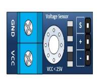
The voltage sensor has two main sides of connections, the input side with two connections (GND and VCC), are connected to the battery poles. The GND connector is connected to the battery negative pole (B -), and he VCC connector is connected to the battery positive pole (B +). While the other side of the sensor (output), contains three connections, (S, + and -), where the (S) connector is connected to the analogue input of the Arduino, and the (+), is neglected as there is no need for it and the (-) connector is connected to the Arduino ground pin.
|
|
|
 |
|
Therefor the sensor detect the battery voltage through the (VCC) connector, and deliver it the microcontroller via (S) connector after modifying this voltage using the voltage divider method. Since the battery voltage is an analogue data, and the computer, as well as the microcontroller does not recognise these type of data, therefor the microcontroller convert this signal to a digital form through the analogue to digital converter, and display this data on the LCD screen, associated with this design which can be comprehended with the software part, that include the functions routine.
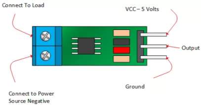
Current sensor
The ACS712 current sensor consist on Alegro ACS712ELC chip, which is provide scale values of 5A, 20 and 30. The one used in this design is with 30A for more safety.
 |
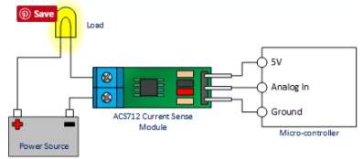 |
This sensor has two sides on connections input and output, where the input side is associated with two connectors, one side is connected to the load, while the other side connected to the battery ground side. Also the output side of this sensor consist on three connectors (VCC, Vout and GND), where the Vout is connected to the microcontroller analogue pin, the VCC is connected to the microcontroller power and the GND connected to the microcontroller ground pin.
Therefor the sensor detect the battery current value through the input connector, and deliver it the microcontroller via (Vout) connector after modifying this current using the voltage divider method. Since the battery current is an analogue data, and the computer, as well as the microcontroller does not recognise these type of data, therefor the microcontroller convert this signal to a digital form through the analogue to digital converter, and display this data on the LCD screen, associated with this design which can be comprehended with the software part, that include the functions routine.
Temperature sensor
The major essence of functionality of the LM35 temperature sensor is converting the between Fahrenheit and Celsius, using these formulas
C° = (F°-32) ÷ 1.8
for Celsius
F° = C° × 1.8 + 32
for Fahrenheit
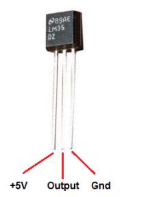
This sensor has three legs connectors (VCC, output and GND), where the sensor itself will be attached to the battery body, the VCC connected to the power supply
(B +) and the GND connected to the battery negative side (B -). The sensor sense the battery temperature and convert it to voltage value that will be transferred to the microcontroller, this signal is an analogue data, therefor the microcontroller convert it to a digital form and display it on the LCD screen.
Software part
As a part of design en electronic circuit, that relay’s on a microcontroller. This smart chip require a structure code, to be configured.
The code used in this design, is a structure of logic blocks, each block contain an individual configuration for a particular element, while these blocks are engaged together within (wile loop), that hold all this blocks, allowing the compiler to read and execute the code when the condition is true.

Code structure
- Include libraries and set the microcontroller pins.

In the code segment above, the liquid crystal LCD screen most be included, since the LCD code routine already configured and installed in the Arduino software, and the aim of using this component is to display the battery’s parameters associated with their values.
- clarify the LCD pins that going to be used
- clarify the microcontroller analogue pin to read the current sensor value
- set variables for current, temperature, power, voltage and battery level
- set the average calibration for current sensor, to avoid any floating during reading process
- create functions for the aimed parameters
- configure the blocks loop routine

The aim of this segment is
- Set the set the communication speed rate between the Arduino and the equipment connected to it (computer and sensor), to be recognised.
- Define the LCD type to be recognised by the Arduino (4 lines and 20 columns)
- Set the delay between the sensors reading and calibrations, for extra accuracy
- Calling code functions

After defining all the functions needed for this structure in the previous, thus, it is possible to call each function when needed without rewriting it again.
- Calculate battery power percentage routine

In the segment, the routine structure for calculating the battery’s power level, after obtaining the battery reading from voltage and current sensors as the follow
It is crucial to obtain the nominal capacity and voltage from battery’s data sheet in order to calculate it energy level.
| Battery nominal capacity and voltage | ||
| Current available per hour | Battery maximum power | Battery voltage |
| 5000 mAh | 66 Wh | 13.2V |
Therefore, from the data sheet it shows that this battery can provide 5 amps current in one hour. Calculating battery’s level percentage can be done using power formula
P= I × V
(where I is the current drawn in one hour, and V is battery voltage)
Therefor
P = 5000 × 13.2 = 66000 mWh
Thus, battery percentage power left is equal maximum power minus actual power multiplied by 1000 (mWh to Wh)
P (left) = max P – (actual) P × 1000
P (percentage) = P (left) P (max) × 100
Therefor battery’ power percentage level
= 100 – P (percentage)
- Calculating battery power routine
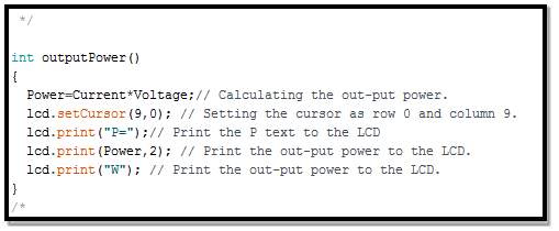
To calculate battery’s power, simply using the voltage value obtained from the voltage sensor and multiply it with current value obtained from the current sensor as the follow
P = V × I
- Reading battery’s voltage routine
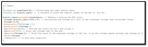
In the code segment above, demonstrate which Arduino analogue input set to read battery’s voltage, and to which digital Arduino output transmitted to convert it from analogue form to digital form. The max Arduino can read 5V, thus configuring the voltage sensor to this value is required.
Since the Atmega328 microcontroller has an 10 bits ADC,
2^10 = 1024
And since the bits count start from zero, thus, it equal to 1023
Therefore, resolution
= 5 (voltage reference )1023 = 4.9 mV
- Reading battery’s current routine

In the code segment above, demonstrate which Arduino analogue input set to read battery’s current, and to which digital Arduino output transmitted to convert it from analogue form to digital form. Beside calibrating this value every second to avoid misreading, and for more accuracy.
From sensor data sheet, every 94m
V = 1 A
Therefore, current value
= (voltage ×1000)94 = A
- Reading battery’s temperature routine
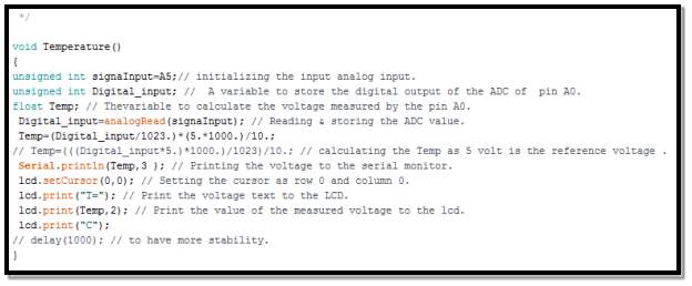
In the code segment above, demonstrate which Arduino analogue input set to read battery’s temperature, and to which digital Arduino output transmitted to convert it from analogue form to digital form.
From temperature sensor data sheet, every 10mV equal to 1C
°
Therefore, battery’s temperature
= (voltage ×1000)10 = C°
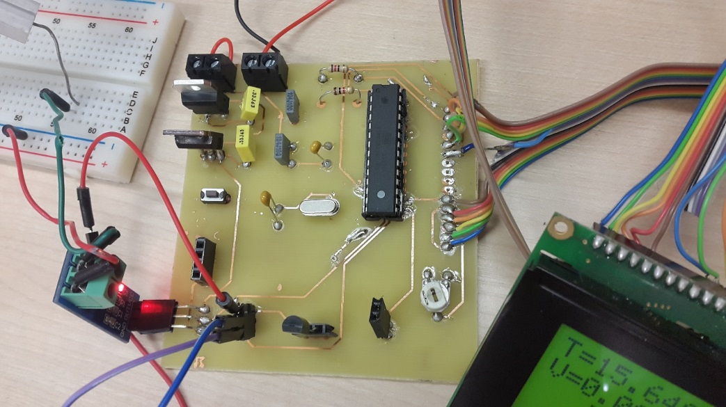
Build and design the device
Result
To detect the current, it is crucial to connect the current input in series with a particular load (resistor) which is connect to the channel two output, and clarify it reading in figure ()
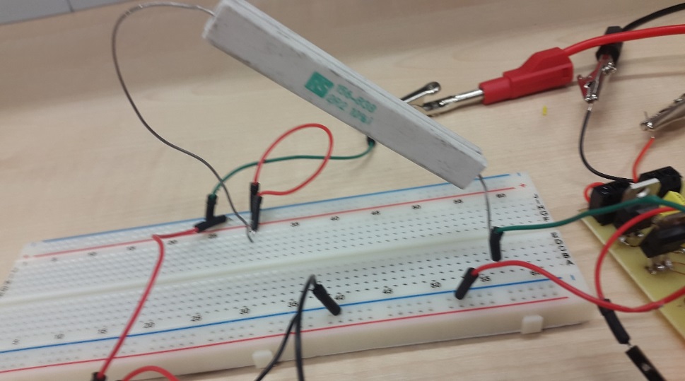
To test the design and approve it reading, it is crucial to use an appropriate power supply (voltage and current) that has two individual channels. One channel to supply the device, while the other to detect it value from the sensors. Which deliver the aimed value beside the potential of changing this value for extra approval.
Initially connect the channel one-power supply to the device, to power it.
Case one
Set the channel one power to a particular value (identical to the battery value), the powering voltage is 10V, bearing in mind that the design can handle 5V only. Thus, the voltage stabilizer used, will regulate the voltage and keep it at suitable level for the design. Set channel two, to a particular value (current is 2 amps and voltage is 7 volts). Connect the voltage sensor input to the channel two output and clarify the reading in
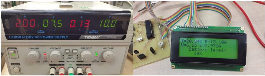
The device reading, were approved, as the circuit display a very close reading to the input applied on the sensors.
| Battery’s parameters | Input sensors | Device reading |
| Voltage | 7.5V | 6.63V |
| Temperature | 20.04C
° |
|
| Current | 2.00A | 1.976A |
| Power consumption | P = V × I.
P = 6.63 × 1.975 = 13.10W |
|
| Battery power level | P (left) = max P – (actual) P × 1000
P (left) = 66000 – 13.10 × 1000 = 52900 W P (percentage) = P (left) P (max) × 100 P (percentage) = 52900 66000 × 100 = 80.15 W percentage level = 100 – P (percentage) 100 – 80.15 = 19.8 W |
|
Case two
Test the design at different value for more accuracy
Change the channel two voltage output to 3.6V, and the current to 1A
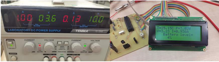
The device reading, were approved, as the circuit display a very close reading to the input applied on the sensors.
| Battery’s parameters | Input sensors | Device reading |
| Voltage | 7.5V | 6.63V |
| Temperature | 20.04C
° |
|
| Current | 2.00A | 1.976A |
| Power consumption | P = V × I.
P = 6.63 × 1.975 = 13.10W |
|
| Battery power level | P (left) = max P – (actual) P × 1000
P (left) = 66000 – 3.02 × 1000 = 62980 W P (percentage) = P (left) P (max) × 100 P (percentage) = 62980 66000 × 100 = 95.04 W percentage level = 100 – P (percentage) 100 – 95.4 = 4 W |
|
Additional and Future work
Adding an extra warning features for the design, such as (buzzer and glowing bulb), is recommended, for safer operation. Since those features will send a warning signals to the driver or to whom it may concern that dealing with Lithium-based battery.
Reduce the design current consumption
Sine Arduino comes in comprehensive board that contain several inputs/outputs, and many more extra component to use it in many application. An extra effort took place, to use the chip by its own, without using the full board into the design, and more important possibly reprogram the chip and apply it in different capacities of batteries.
To carry out this procedure, the following steps for burning the bootloader is required for the chip is followed
- Connect the Arduino board to PC, and upload the ISP burning bootloader routine into the chip.
- Select the Arduino type within Arduino software
- Run the ISP tool
The benefit of using this method is crucial, as it reduces the design current consumption from 10mA to 3mA.
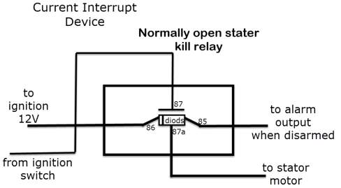
How to solve catching fire
Eventually bursting into flames or detonating, is tackled with a built-in device breaker (current interrupt device or CID), so when the battery is charged completely, it prevents the charging current to flow into it, as well as when the battery’s temperature and/or or pressure exceed the limit.
Discussion
To monitor a particular system. It is crucial to study the aimed system component beside it characteristic, by doing so, it is possible to determine the system parameters that change it behaviour in a varying conditions, which, will clarify the exact parameters need to be targeted within this monitoring process.
Based on the above case study, the cars electric system consist on three main electric circuits.
- Starting and charging circuit, this circuit is a closed loop system that becomes active as soon as the switch is turned on. When the switch at starting position, current flows from the battery to the starter, where this current amplified through coils and becomes suitable to start the engine through the start plugs. Once the engine turned on, the alternator start to rotate and generate electric current, this current is a AC current and it is varying due to the speed variation, therefore AC current turn to be a DC current by the rectifier, and regulated by the regulator and back to charge the battery.
- Load power supply circuit, the power for this circuit is supplied from the alternator when the engine is on, otherwise the battery deliver the power needed.
- Monitoring circuit, this circuit is connect directly to the battery that detect battery status.
Choosing a suitable method to proceed with this project, should also be based on the following
- Detect the targeted parameters, and display the changing behaviour under different conditions at all time.
- Accurate and easy to maintain
- Cheap and economic
Since the existing signals in real, world such as voltage, current and temperature are an analogue signals. In other hand those signals are continuous in amplitude and time. While the computer and microcontroller does not recognise those type of data, converting those signals to digital data (discrete in amplitude and time) is required.
By analysis the available monitoring methods, the Raspberry pi, is rejected as it does not contain (AD converter). Thus, the Arduino technology used, notably adding a secondary circuit (AD convertor) to Raspberry pi is possible, but it the cost will increase, and so the power consumption.
Using an independent power supply connector for voltage, current and temperature sensors in recommended, due to the effect of each sensor to the other, which will reduce the accuracy of this design. Thus, an individual voltage stabiliser is required for each sensor.
Conclusion
In this report elucidated, that similarly as an individual cell may not act consistently under varying current conditions, so a whole battery pack is likewise powerless to non-uniform current passing through individual cells when there are parallel strings display in the pack. This is especially intense under high-C charge or release conditions.
There are some certain ramifications for the monitoring system and battery management design of a lithium-based battery in this kind of parallel course of action. To begin with this design voltage detecting must be operated periodically under different conditions (varying temperature, varying current consumptions and varying engine speed) where the voltage changes is relied upon to be most exceedingly bad. Second, a dynamic balancing may need to incorporate a postponement before reading the battery’s parameters keeping in mind the end goal to enable time for uninvolved balancing current to reach inside the battery.
As lithium batteries are the main energy sources in the Formula Student Vehicle (FSVs), their status, extraordinarily impacts the performance of this vehicle and any other vehicles that depends on Lithium-based battery.
Accordingly, maker’s enthusiasm expanding in these two perspectives, lithium battery technology and battery monitoring systems. Chemical characteristic in these batteries are subject to performing status, and thus, the corruption of a battery may fluctuate in various conditions.
The prime objective of this of monitoring the lithium-based battery were discussed and clarified within this report which include
- Lithium-based battery characteristic, and changing behaviour under several conditions
- Car’s electric system component
- Define the battery parameters that need to be monitored
- Choose the best monitoring method that suit this project
- Design and test the monitoring design and ensure it safe operation
References
- Wagner, R., Preschitschek, N., Passerini, S., Leker, J., & Winter, M. (2013). Current research trends and prospects among the various materials and designs used in lithium-based batteries. Journal of Applied Electrochemistry, 43(5), 481-496. doi:10.1007/s10800-013-0533-6
- Kim, G. -., Jeong, S. S., Xue, M. -., Balducci, A., Winter, M., Passerini, S., . . . Appetecchi, G. B. (2012). Development of ionic liquid-based lithium battery prototypes. Journal of Power Sources, 199, 239-246. doi:10.1016/j.jpowsour.2011.10.036
- Wang, B., Li, X., Qiu, T., Luo, B., Ning, J., Li, J., . . . Zhi, L. (2013). High volumetric capacity silicon-based lithium battery anodes by nanoscale system engineering. Nano Letters, 13(11), 5578-5584. doi:10.1021/nl403231v
- Ferrari, S., Capsoni, D., Casino, S., Destro, M., Gerbaldi, C., & Bini, M. (2014). Electrochemistry of orthosilicate-based lithium battery cathodes: A perspective. Physical Chemistry Chemical Physics : PCCP, 16(22), 1353-1366. doi:10.1039/c4cp00511b
- Jana, A., Ely, D. R., & García, R. E. (2015). Dendrite-separator interactions in lithium-based batteries. Journal of Power Sources, 275, 912-921. doi:10.1016/j.jpowsour.2014.11.056
- Ummartyotin, S., & Manuspiya, H. (2015). An overview of feasibilities and challenge of conductive cellulose for rechargeable lithium based battery. Renewable and Sustainable Energy Reviews, 50, 204-213. doi:10.1016/j.rser.2015.05.014
- Hassoun, J., Bonaccorso, F., Agostini, M., Angelucci, M., Betti, M. G., Cingolani, R., . . . Scrosati, B. (2014). An advanced lithium-ion battery based on a graphene anode and a lithium iron phosphate cathode. Nano Letters, 14(8), 4901-4906. doi:10.1021/nl502429m
- Watrin, N., Ostermann, H., Blunier, B., & Miraoui, A. (2012). Multiphysical lithium-based battery model for use in state-of-charge determination. IEEE Transactions on Vehicular Technology, 61(8), 3420-3429. doi:10.1109/TVT.2012.2205169
- Huang, Q., Yang, J., Ng, C. B., Jia, C., & Wang, Q. (2016). A redox flow lithium battery based on the redox targeting reactions between LiFePO4 and iodide. Energy and Environmental Science, 9(3), 917-921. doi:10.1039/c5ee03764f
- Krieger, E. M., Cannarella, J., & Arnold, C. B. (2013). A comparison of lead-acid and lithium-based battery behavior and capacity fade in off-grid renewable charging applications. Energy, 60, 492-500. doi:10.1016/j.energy.2013.08.029
- Poyraz, A. S., Huang, J., Cheng, S., Bock, D. C., Wu, L., Zhu, Y., . . . Takeuchi, E. S. (2016). Effective recycling of manganese oxide cathodes for lithium based batteries. Green Chemistry, 18(11), 3414-3421. doi:10.1039/c6gc00438e
- Hassoun, J., Lee, K., Sun, Y., & Scrosati, B. (2011). An advanced lithium ion battery based on high performance electrode materials. Journal of the American Chemical Society, 133(9), 3139-3143. doi:10.1021/ja110522x
- Capasso, C., & Veneri, O. (2014). Experimental analysis on the performance of lithium based batteries for road full electric and hybrid vehicles. Applied Energy, 136, 921-930. doi:10.1016/j.apenergy.2014.04.013
- Wang, J. L., Yang, J., Xie, J. Y., Xu, N. X., & Li, Y. (2002). Sulfur–carbon nano-composite as cathode for rechargeable lithium battery based on gel electrolyte. Electrochemistry Communications, 4(6), 499-502. doi:10.1016/S1388-2481(02)00358-2
- Du, F., Zhao, N., Li, Y., Chen, C., Liu, Z., & Guo, X. (2015). All solid state lithium batteries based on lamellar garnet-type ceramic electrolytes. Journal of Power Sources, 300, 24-28. doi:10.1016/j.jpowsour.2015.09.061
- Huang, K., & Zhang, Q. (2012). Rechargeable lithium battery based on a single hexagonal tungsten trioxide nanowire. Nano Energy, 1(1), 172-175. doi:10.1016/j.nanoen.2011.08.005
- Wang, G. J., Yang, L. C., Qu, Q. T., Wang, B., Wu, Y. P., & Holze, R. (2010). An aqueous rechargeable lithium battery based on doping and intercalation mechanisms. Journal of Solid State Electrochemistry, 14(5), 865-869. doi:10.1007/s10008-009-0869-3
- Kwon, Y. H., Woo, S., Jung, H., Yu, H. K., Kim, K., Oh, B. H., . . . Kim, J. Y. (2012). Cable-type flexible lithium ion battery based on hollow multi-helix electrodes. Advanced Materials, 24(38), 5192-5197. doi:10.1002/adma.201202196
- Angenendt, K., Johansson, P., Chalmers University of Technology, Institutionen för teknisk fysik, Kondenserade materiens fysik, Chalmers tekniska högskola, School of Physics and Engineering Physics, & Department of Applied Physics, Condensed Matter Physics. (2011). Ionic liquid based lithium battery electrolytes: Charge carriers and interactions derived by density functional theory calculations. Journal of Physical Chemistry B, 115(24), 7808-7813. doi:10.1021/jp2036108
- Baghdadi, I., Briat, O., Gyan, P., & Vinassa, J. M. (2016). State of health assessment for lithium batteries based on voltage–time relaxation measure. Electrochimica Acta, 194, 461-472. doi:10.1016/j.electacta.2016.02.109
- Liu, H., Wang, Y., Yang, W., & Zhou, H. (2011). A large capacity of LiV3O8 cathode material for rechargeable lithium-based batteries. Electrochimica Acta, 56(3), 1392-1398. doi:10.1016/j.electacta.2010.10.049
- Chen, Y., Qu, B., Hu, L., Xu, Z., Li, Q., & Wang, T. (2013). High-performance supercapacitor and lithium-ion battery based on 3D hierarchical NH4F-induced nickel cobaltate nanosheet-nanowire cluster arrays as self-supported electrodes. Nanoscale, 5(20), 9812-9820. doi:10.1039/c3nr02972g
- Yao, W., Zhao, J., Wen, F., Dong, Z., Xue, Y., Xu, Y., & Meng, K. (2014). A multi-objective collaborative planning strategy for integrated power distribution and electric vehicle charging systems. IEEE Transactions on Power Systems, 29(4), 1811-1821. doi:10.1109/TPWRS.2013.2296615
- Faschang, M., & Kupzog, F. (2013). Interfacing vehicle charging systems with user and grid requirements. Informatik-Spektrum, 36(1), 27-34. doi:10.1007/s00287-012-0664-x
- Kang, T., Kim, C., Suh, Y., Park, H., Kang, B., & Kim, D. (2012). A design and control of bi-directional non-isolated DC-DC converter for rapid electric vehicle charging system. Paper presented at the 14-21. doi:10.1109/APEC.2012.6165792
- Fekete, P., Lim, S., Martin, S., Kuhn, K., & Wright, N. (2016). Improved energy supply for non-road electric vehicles by occasional charging station location modelling. Energy, 114, 1033-1040. doi:10.1016/j.energy.2016.08.061
- Robertson, S. (2001). Automotive electrical maintenance. Oxford: Newnes
- Lawes, J. (2006). Competition car electrics: A practical handbook. Sparkford: Haynes
- Williams, T. (1991). The circuit designer’s companion. Oxford: Butterworth-Heinemann.
- Global light vehicle wiring market- forecasts to 2029. (2015). Just – Auto, , 1.
- Heisler, H. (1999). Vehicle and engine technology (2nd ed.). Oxford: Arnold.
- Beckford, J. (2010). Quality: A critical introduction (3rd ed.). New York;London;: Routledge.
- Warwick manufacturing group launches simplified car wiring (2000). . London: Caspian Publishing Limited.
- Denton, T. (1995). Automobile electrical and electronic systems. London: Edward Arnold.
- Denton, T. (2011). Automobile mechanical and electrical systems: Automotive technology, vehicle maintenance and repair. Amsterdam;London;: Butterworth-Heinemann
- Waag, W., Fleischer, C., & Sauer, D. U. (2014). Critical review of the methods for monitoring of lithium-ion batteries in electric and hybrid vehicles. Journal of Power Sources, 258, 321-339. doi:10.1016/j.jpowsour.2014.02.064
- Kim, T., Wang, Y., Fang, H., Sahinoglu, Z., Wada, T., Hara, S., & Qiao, W. (2015). Model-based condition monitoring for lithium-ion batteries. Journal of Power Sources, 295, 16-27. doi:10.1016/j.jpowsour.2015.03.184
- Weng, C., Feng, X., Sun, J., & Peng, H. (2016). State-of-health monitoring of lithium-ion battery modules and packs via incremental capacity peak tracking. Applied Energy, 180, 360-368. doi:10.1016/j.apenergy.2016.07.126
- Hong, X., Li, N., Kong, Q., Liu, G., & Ho, M. (2016). Local cell temperature monitoring for aluminum shell lithium-ion battery based on electrical resistance tomography. Measurement, 86, 227-238. doi:10.1016/j.measurement.2016.02.039
- Hughes, John M. (Systems engineer). (2016). Arduino: A technical reference : A handbook for technicians, engineers, and makers (First ed.). Beijing: O’Reilly
https://en.wikipedia.org/wiki/Lithium_battery
- Current sensor
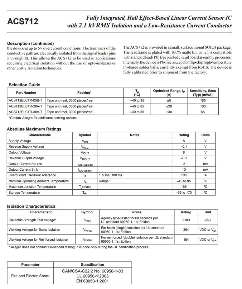
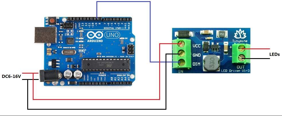 |
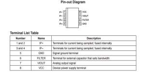 |
Voltage sensors


- Temperature sensor
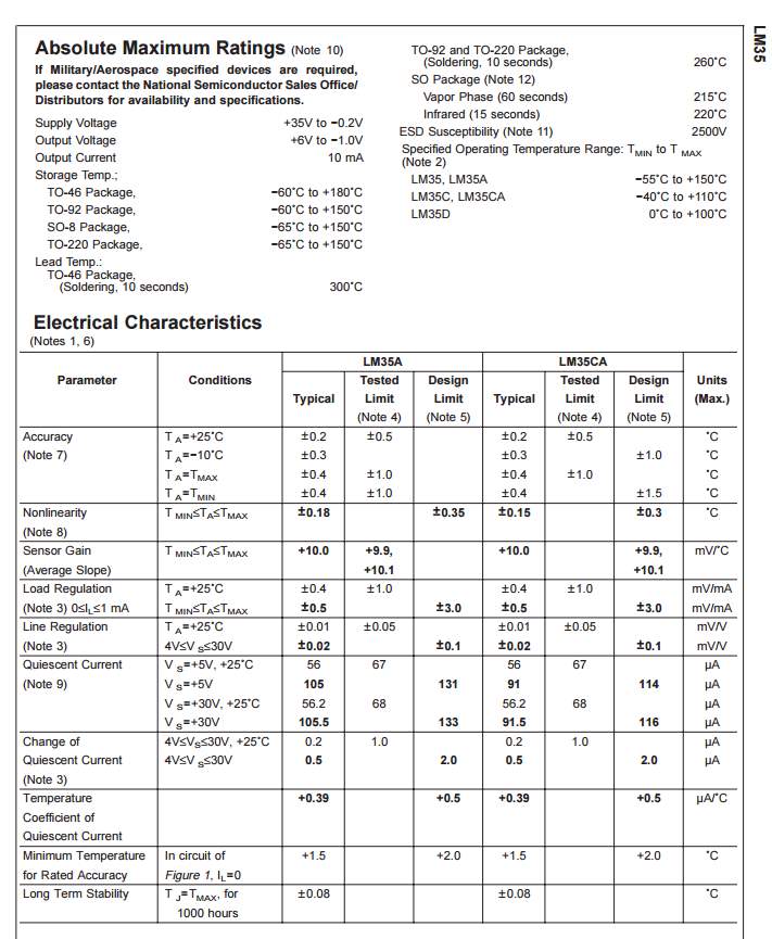
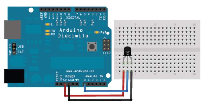
Atmega323 chip
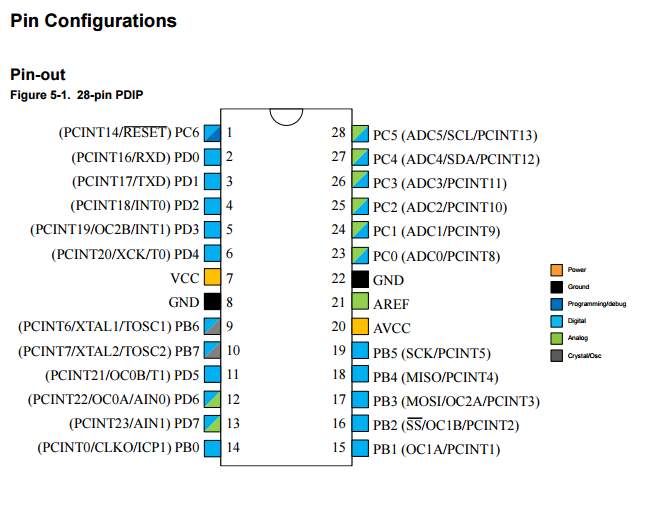
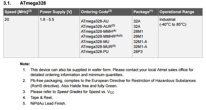
- . 4*20 LCD secreen
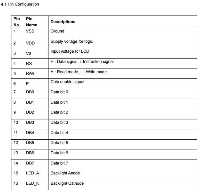
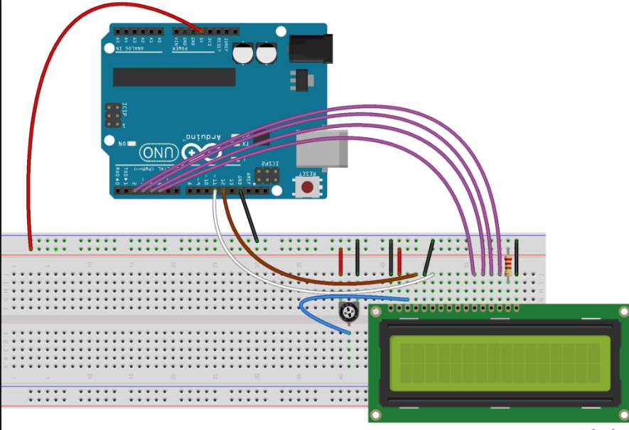
Voltage regulator. LM217
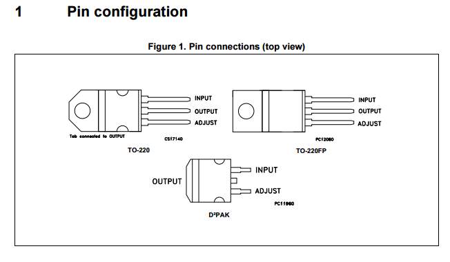
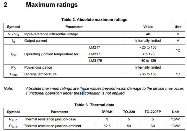
Potentiometer

Cite This Work
To export a reference to this article please select a referencing stye below:
Related Services
View all


Related Content
All TagsContent relating to: "Energy"
Energy regards the power derived from a fuel source such as electricity or gas that can do work such as provide light or heat. Energy sources can be non-renewable such as fossil fuels or nuclear, or renewable such as solar, wind, hydro or geothermal. Renewable energies are also known as green energy with reference to the environmental benefits they provide.
Related Articles

DMCA / Removal Request
If you are the original writer of this dissertation and no longer wish to have your work published on the UKDiss.com website then please: