Laser Mobile Mapping System Prototype Using Riegl TLS VZ-400 with IMU & GNSS
Info: 4786 words (19 pages) Dissertation
Published: 9th Dec 2019
Tagged: GeographyEarth Sciences
ABSTRACT
The research on the Laser Scanner based mobile mapping system is becoming industry standard tool for collecting accurate 3D terrain data along the corridors at a faster speed. Airborne laser scanning system also provides the LiDAR mobile mapped data but they are expensive and with low resolution as compared with land based laser scanners. Though, development of land-based mobile mapping system by integrating the laser ranging, inertial navigation & position sensors can be carried out in the extent of the study with Riegl laser scanner which is very rare in India. Seeing this, the thesis aims at the design & development of laser mobile mapping system prototype using Riegl TLS VZ-400 with IMU & GNSS. The standard procedure of the Mobile Mapping System development is divided into different stages, which include integration of Terrestrial Laser Scanner (TLS) with Inertial Measurement Unit (IMU) & Global Navigation Satellite System (GNSS), Orientation of the mounted sensors has been carried out to form a common coordinate system and offsets parameters between them were calculated precisely. System calibration is conducted for the estimating the offset vectors and misalignment matrices and were determined by georeferencing the set of static scenes with 15 ground control points (GCPs), which was previously surveyed in instrument reference frame and UTM 44 N geographic coordinate system using total station. Further, scans were taken in Line scan mode for mobile mapping at varying speed, an algorithm is modified and developed a code for the direct georeferencing of point cloud data. For the precise dense point cloud georeferenced data- Riegl Vz-400 has been used as Laser Scanner, Trimble R7 GNSS in PPK (Post processing kinematics) mode and Microstrain 3DM-GX4-45 IMU were used. Software based approach for time synchronization module has been setup for synchronizing the TLS with the GPS time. Trajectory information, orientation parameters, calibration parameters and raw laser data are used for Geolocating the laser footprints. All the parameters and measurements were carefully noted at the time of system integration and preprocessing, which provided the precise level of accuracy. Finally, system operation and execution is performed at the test sites in IIRS campus, and various parameters & observations has been made such as Average data density of 5872 points/square meter, swath of 100 degrees and horizontal spacing of 15cm between the scan lines are achieved.
Keywords: LiDAR, Mobile mapping, Georeferencing, Geolocation, software based time synchronization module, GNSS, Riegl Vz-400.
CHAPTER 1 : INTRODUCTION
1.1. Background
Mobile LiDAR is a broadly castoff term for a laser scanner deployed on any mobile platform such as a van, boat, and often does not infer an airborne LiDAR. However, the general principles of the process are the same for airborne and ground-based mobile LiDAR systems. As per the increasing demand for large-scale high-speed data acquisition with minimal effort brings the concept of Mobile Mapping Systems (MMS). Some regularly used conventional methods of large scale spatial data collection are airborne LiDAR, aerial photogrammetry and terrestrial surveying using a total station and GPS. All afore said methods have own limitations, such as acquiring data using terrestrial surveying with total station and GPS is effort intensive and much time consuming, while in case of aerial surveying various features like electric poles, road sign boards and principal front of a buildings may not be captured properly or the data may be available at very low resolution. A land based Mobile Mapping System, which is equipped with mapping and navigation sensors, is capable of acquiring three-dimensional data (features like electric poles & wires) in a short duration of time. Some of the most noticeable uses of Mobile Mapping System, especially in the Indian context are (i) Applications for Highways like Traffic sign catalogue, inspection of road condition survey and highway corridor mapping; (ii) Railway uses like minimum track clearance and Track geometry; (iii) Applications in Urban like generation of 3D models, (iv) Encroachment mapping and monitoring. Foremost and challenging applications of developed MMS are updating existing maps including highway and city (both urban and rural) maps, determination of the value of buildings (commercial, residential etc.) (Yadav., Manohar et al).
1.1.1 Terrestrial Mobile Mapping
Mobile Mapping is the most emerging technique for spatial data acquisition in the field of GIS and gaining the high importance because of the advantages such as time consumption is less, easy data acquisition and high flexibility, (Li, 1997). As the name signifies, the mobile mapping comprises of a moving or mobile platform, navigation (GPS, INS etc.) and mapping sensors. An aircraft or any other land based vehicle can be used as the mobile platform. To capture the information of the objects to be surveyed, mapping sensors are employed that can be metric or non-metric cameras, laser scanners or radars. Navigational sensors like Global Positioning Systems (GPS) and Inertial Navigation Systems (INS) are used to provide the position and orientation information of the mapping sensor, (Li, 1997). The acquired point cloud or images can be directly geo-referenced by measuring the position and attitude of the mapping sensors using GNSS/INS system. The importance of mobile mapping system is in its efficiency for rapid acquisition of geometric information of ground objects. (Ka et al., 2011).

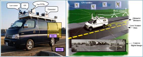 The above structure of Mobile Mapping System describes the general outline of the complete mobile mapping mechanism; a vehicle equips the necessarily synchronized devices for data collection in kinematic mode. After the acquisition, the data need to process to generate the products like precise georeferenced point cloud, digital maps, images and GIS data. Furthermore, figure 1.2 shows the typical mobile mapping system and Table 1.1 provides the summary of MMS related sensors.
Table 1‑1 Summary of the MMS sensors (Naser, 2005)
| Sensors Type | Characteristics/Properties |
| CCD Cameras |
|
| Imaging Laser |
|
| Laser Scanner |
|
| GNSS |
|
| Inertial Sensors (INS/IMU) |
|
| DMI( Distance Measurement indicator) |
|
All the mobile mapping systems have a common feature is that, all sensors attached on a single platform are required to solve a specific problem of synchronizing the data accurately.
1.1.2 Subsystem of Mobile Mapping System.
The survey technique basically relies on the three main hardware parts. These include Laser ranging/Scanning devices, Imaging devices and the positioning & orientation devices. Further, in order to successfully build the mobile mapping system, a vehicle with the mounting platform and supporting accessories are required.
A. Laser Ranging & Scanning Component
These devices used for measuring range between the center of the scanning mirror and the ground point hit by laser pulses as a raw observation. The several, diverse and quite established types of tripod-mounted 3D laser scanners that are in widespread use by land surveyors undertaking terrestrial or ground-based laser scanning including both panoramic and camera-type laser scanners. These are mainly used for static measurements in their native 3D operation mode. However much less number of 3D laser scanners are used in mobile platform like German FARO and Z+F companies have been operated on mobile mapping vehicles, but with their horizontal (azimuth) angular movement disabled and ILRIS-3D from Optech with vertical (elevation) angular movement disabled which transform their functionality like a 2D laser scanner. But, in mobile mapping systems mainly 2D laser scanners are used to measure range and angular values of each laser shot on single 2D plane. The 2D laser scanners, most commonly used in mobile mapping, are- (i) SICK LMS 291 2D laser scanner manufactured by the SICK company, which is based in Waldkirch, Germany, (ii) longer range laser scanners from LASE GmbH, which is another company in the SICK Group based in Wesel, Germany, and (iii) Riegl Vz-series i.e vz-400, vz-1000 followed by Q120, VQ-180, VQ-250 from Riegl based in Horn, Austria. Optech does not supply its laser scanners alone but manufactured to use in its own LYNX Mobile mapping system. All these laser scanners use rapid laser rangefinder using the time-of-flight (TOF) distance measuring principle with continuously rotating polygon mirror with in-built angular encoder for measurement of angular directions of fired laser pulse. Laser scanners from Reigl and Optech provide greater ranges, faster speeds and higher measuring accuracies than those provided by the SICK (Laser scanner manufacturer) laser scanners but at a cost of higher manufacturing price (Petrie G., 2010).
B. Imaging components
Imaging devices are used to obtain texture and color information of a terrain in the form of pixel data. Due to higher speed measure of the mapping vehicle and the closeness of the target objects (around few tens of meters), the digital frame cameras with higher framing rates (typically 7 to 15 frames per second), short exposure time to avoid image blurring and multiple camera arrays to cover 360 degree panoramic images in the horizontal plane are used (Petrie G., 2010). However, the sizes are very small (typical 1 to 2 Megapixels) and the use of fully integrated multiple camera arrays to deliver 360-degree panoramic images in the horizontally is common in mobile mapping vehicles. Ladybug arrangement of numerous cameras worked by Point Gray Research, situated in Richmond, B.C., Canada and Dodeca camera formulated by another Canadian organization, Immersive Media Corporation Inc. (IMC), situated in Calgary, Alberta are regularly utilized envision sensors by for the most part accessible portable mapping frameworks. (Petrie G., 2010).
C. Georeferencing Components
Georeferencing components consist of IMU (Inertial Measurement Unit), GPS/GNSS (Global Navigation Satellite System) and DMI (Distance Measurement Instrument), these all the georeferencing components are described in the following sections.
i. Lord MicroStrain Sensing Systems GPS-Aided Inertial Navigation System (GPS/INS) 3DM-GX4-45
Orientation devices used for measurement of the angular movement of the system/vehicle on which all devices are rigidly mounted, about three axes of the coordinate system defined by orientation measuring devices. There are a large number of IMU devices that can generate a continuous stream of position and orientation data LORD Corporation MicroStrain® Sensing Systems located in Williston, USA, manufactures and supplies the system globally.
Specifications of the IMU:-
Table 1‑2 Specification of Inertial Navigation System source: lord user manual
| Inertial Measurement Unit (IMU) Sensor Outputs | |||
| Accelerometer | Gyroscope | Magnetometer | |
| Measurement range | ±5 g (standard)
±16 g (option) |
300°/sec
(standard) ±75, ±150, ±900 °/sec (options) |
±2.5
Gauss |
| Non-linearity | ±0.03 % fs | ±0.03 % fs | ±0.4 % fs |
| Resolution | <0.1 mg | <0.008°/sec | — |
| Bias instability | ±0.04 mg | 10°/hr | — |
| Initial bias error | ±0.002 g | ±0.05°/sec | ±0.003 Gauss |
| Scale factor stability | ±0.05 % | ±0.05 % | ±0.1 % |
| Noise density | 100 μg/√Hz | 0.005°/sec/√Hz | 100 μGauss/√Hz |
| Alignment error | ±0.05° | ±0.05° | ±0.05° |
ii. Global Navigation Satellite System (GNSS)
Navigation is a field of study that focuses on the process of monitoring and controlling the movement from one place to another, along with our coordinates we require to know the linear accelerations, angular acceleration and angular coordinates i.e. Roll, Pitch & Yaw. Global Navigation satellite system (GNSS) can deliver the user his Latitude and Longitude position on earth quickly and in real time, GNSS system utilizes satellites orbiting the earth that broadcast signals using very precise frequencies and highly accurate atomic clocks for time. Any receiver on the ground can pick up the GNSS broadcast as long as they are coded to read the signal. GNSS signals are around us at all times and broadcasts for free. As the GNSS signals travel through the atmosphere, the signal can become distorted leading to reduce positional accuracy deliver to the receiver. GNSS signals that are from satellites which are low on the horizon or (called low zenith) are difficult to pick up and more likely to have errors because they are traveling to more of the atmosphere to get to the receiver. It uses the groups of satellites or constellations for their systems, for a receiver to establish a position it must be tracking four satellites or more.
A GNSS system consists of three segments: the satellites orbiting the Earth, Ground stations for monitoring and tracking the satellites and provide the facility to the users to compute their position and motion. There are several independent GNSS in operation today:
- GPS, developed & operated by USA
- GLONAAS, developed & operated by Russia
- BeiDou, developed & operated by China
- Galileo, developed & operated by European union
GPS is based on a constellation of 24 to 32 satellites and is very popular among all GNSS because of its well orbital distribution operated by the USA Department of Defence (DoD). They circle about 22,000kms above the Earth twice a day in precise orbits. Satellites regularly transmit coded information in UHF band back to GPS receivers on the ground and available free for all worldwide civilian users.
GLONAAS is the satellite navigations system by Russian Aerospace Defense Forces with approx. 24 satellites in operation orbiting at a similar altitude as GPS satellites. GLONASS broadcasts on two frequencies and will be expanding to 3 frequencies with future satellite launches.
BeiDOU satellite navigation system by China National Space Administration also many times called COMPASS, it has both regional and global satellites in the space, it is still being deployed but provides operational coverage in India, Asia, Australia, Russia, Europe & Africa.
GALILEO satellite navigation operated by the European Space Agency, GALILEO is also still being deployed when complete will consist of approx. 30 satellites.
The accuracy level in the cases are in meter level, thus here is a necessity of better accuracy/precision for accurate mapping and it can be attained by using differential Global Positioning System to increase accuracy up to centimeter level. Differential GPS (DGPS) positioning is a technique which provides centimeter level accuracy depending on several aspects including the use of two different GPS receivers (JARIWALA, J. J. (2013)) One receiver is called base or reference receiver and the second receiver is called roving receiver or rover. The base station is positioned at a point where the exact location is already known accurately, whereas the rover moves over the points to be located. There are mainly four approaches of DGPS positioning: static-post processing, static-real time processing, dynamic with real-time processing and dynamic with post processing. At each point, the satellite data from at least 4 different satellites is stored in the receiver (JARIWALA, J. J. (2013)). In the meantime, the base also tracks the same satellite and records similar data, but for two different location. Thus at the same time, both the base and rover track the same satellites and store similar data which delivers centimeter-level accuracy in both 2D and 3D (NRC, 1995). This level of accuracy is often desirable to measure/draw points, lines and polygon for a Geographic Information System (GIS) or for mapping purpose.
Table 1‑3 Function of GNSS segments along with input and output information (NRC, 1995) and (iirs.gov.in)
| Segment | Input | Output | Functions |
| Space | Navigation Message | Navigation Message transmits on P (pseudo) and C/A Code, L1(1575.42 MHz), L2 (1227.60 MHz) carrier | Generate code, carrier phase to transmit navigation message |
| Control | P-Code observation time | Navigation Message | Product GNSS time, predict ephemeris, manage space vehicles |
| User | Carrier Phase Observation, Code observation, Navigation Message | Position, Velocity, Time | Surveying and Navigation Solution |
In this study differential ‘Trimble R7 GNSS system’ is used for accurate georeferencing, following are the technical and positioning specification of the GNSS used.
Table 1‑4: Performance Specification of R7 GNSS
| PERFORMANCE SPECIFICATIONS | ||
Measurements
|
||
| Positioning Performance | ||
| Horizontal | Vertical | |
| Code differential | 0.25 m + 1 ppm RMS | 0.50 m + 1 ppm RMS |
| Static & Fast static | 3 mm + 0.5 ppm RMS | 5 mm + 0.5 ppm RMS |
| Kinematics surveying | 8 mm + 0.5 ppm RMS | 15 mm + 1 ppm RMS |
| Initialization time = 7 minutes in PPK (post processed kinematics) & in RTK with radio typically within 10 seconds | ||
| Temperature:
Operating. . . . . . . . . . . . . . . . . . . . . . . . . .–40 °C to +65 °C (–40 °F to +149 °F) Storage. . . . . . . . . . . . . . . . . . . . . . . . . . . .–40 °C to +80 °C (–40 °F to +176 °F) Humidity. . . . . . . . . . . . . . . . . . . . . . . . . . . . . . . . . . . . . . . . . . . . 100%, condensing Water/dustproof. . . . . . . . . . . . . . . . . . . . IP67 dustproof, protected from temporary immersion to depth of 1 m (3.28 ft) |
||
1.1.3 Constituents of Mobile Mapping System
- Device setup
- Calibration of the system
- Data Acquisition
- Kinematic modeling
- Synchronization
- Direct-Georeferencing
- Quality Control
A. Device Setup
The mobile mapping system consists of mapping sensors like metric/non-metric camera, laser scanner or radars etc.; Inertial Navigation Systems (INS), DMI’s, power system, data collection & processing device. All the devices have to setup/installed in a stable and appropriate manner so as to sustain the roads undulations and jerks without major system disturbance.
B. Calibration of the system
Calibration of the system expresses the accurateness and quality measurements of the system recorded using any device/equipment. It is an association among the various measurements taken by the one equipment with the observation taken by same equipment at the different time or from different locations OR in a similar way with the different equipment. The equipment/device with the assigned or known value is called standard. The goal of the calibration is to minimize the uncertainty of the device/equipment(s), calibration measures and control errors or uncertainties in measurement process to an acceptable level.
C. Data Acquisition:
The data acquisition module contains imaging, laser and navigation sensors. Navigation instruments/sensors are used to resolve the georeferencing issues. Although various systems are used in general navigation, relatively stringent necessities in terms of accuracy and environment brought the integration of an INS with GPS receivers the core of any sensor arrangement for short range accurate mobile mapping system (Naser, 2005). This combination also offers substantial redundancy and brings the use of additional sensors for reliability purposes usually unnecessary (Naser, 2005).
D. Kinematic Modeling:
The determination of Kinematic modeling for a rigid body in the relative measurement of some reference coordinate frame. The rigid body is in the terms of finite dimensions, which maintains its property of all its points on various relative positions defined in the coordinate frame. The general motion of any rigid body in the space can be described by six parameters, three orientations and three positions. The rigid body modeling can be represented by an equation (Naser, 2005):
Vehicle coordinate system referenced all units to a single system were manufactured by various organizations.
MARINE-BASED MMS
(Boeder, V., Kersten, T. P., Hesse, C., Thies, T., & Sauer, A. (2010)) studied and implemented the combination of two different scanners, in this paper initial experience of the two terrestrial laser scanning systems IMAGER 5006i from Zoller + Fröhlich and Riegl VZ-400 are integrated in the mobile hydrographical multi-sensor system will be presented. This system was installed on two different ships situated in Hamburg. In a first case study the ship Level-A from the HafenCity University Hamburg (HCU), which is well-matched for operations in shallow water areas, tested the terrestrial laser scanner IMAGER 5006i in combination with the hydrographic sensors onboard. The second study was carried out with the terrestrial laser scanner Riegl VZ-400, which had been installed on the another ship from the Hamburg Port Authority. The use of terrestrial laser scanner systems on board of surveying ships shows the data acquisition by such systems can be integrated into the hydrographical multi-sensor system both in post processing mode and in real-time. By the use hydrographical multi-sensor technology, data can be acquired at the high speed, the affluence of 3D coordinates, reflecting characteristics and the accuracy of the acquired point clouds within centimeter range at and on the water. The QNIS software plays a key role for the integration of terrestrial laser scanning in real time for the investigation of terrestrial laser scanner in real time for the investigations at HCM and NIAH. The pure accuracy of the inertial measurement units significantly effects the accuracy and quality of the kinematic laser scanning data. The Reigl VZ-400 terrestrial laser scanner has an advantage due to its technical specifications in scanning range, accuracy and resolution. In comparison to both, the surveying ships the Regil VZ-400 is having advantage. The performance of each system is demonstrated by the sensor integration is tested for these two multi sensor systems two objects were scanned in two selected areas of the harbor of hamburg and wedel. To verify the accuracy of the kinematic laser scanning system on the ship some reference data has been scanned with static laser scanning. The integration of the terrestrial laser scanner system and test procedures are studied.
2.1.2 Calibration & Error analysis system
Calibration holds great importance as it is one of the major steps that must be carried before using the system in operational basis. This process is primarily divided into two sections, stated as- individual sensor calibration and complete system calibration. The system calibration can be explained as the process for estimating the spatial relationship among two components, sensor used for mapping and navigation sensor. The system calibration is the foremost step for direct or combined sensor orientation. Andreas et al explained the importance of calibration and also evaluated the accuracy of the calibrated system using the transformation approach (Rietdorf, Gielsdorf, & Gruendig, 2003). Major factors covered by such type of calibration are “boresight misalignment, GPS antenna offsets and time synchronization errors and interior orientation of sensor” (Yastikli, 2004). There have been various algorithms introduced since long for calculating the misalignment errors which is found between the measurement axes of inertial measurement unit (IMU) and laser scanning device. Some of the procedures includes the terrestrial test site which is thoroughly surveyed for obtaining the accurate coordinates. These coordinates can be estimated using retro reflective targets whose shape and size are already known (Rieger, Studnicka, Pfennigbauer, & Zach, 2010). Lever- arm offsets and boresight angles are the two major errors which are calculated using integrated system orientation procedure. The mathematical analysis of the same is explained in (Rau et al., 2011). In case of the mobile mapping systems the camera and the navigation sensor system are rigidly mounted on a moving platform hence it is assumed that there geometric relationship remains constant. Further the mounting parameters can be estimated using two-way and single step procedures as explained by Rau et al., 2011. The errors which are found in mobile mapping system is well described in (Glennie, 2007).
(Ellum, C., & El-Sheimy, N. (2002, May)) worked using multi-sensor / Mobile Mapping Systems (MMS) has been a ubiquitous mapping tool these days, this study focus on the calibration of the integrated system used for the data collection. Three elements of integrated system calibration are examined: camera calibration, boresight calibration, and lever-arm calibration. Camera calibration determined interior geometry such as the camera’s focal length (c) and principal point offsets.
Cite This Work
To export a reference to this article please select a referencing stye below:
Related Services
View all


Related Content
All TagsContent relating to: "Earth Sciences"
Earth Sciences is a field of study that focuses on the science behind planet Earth. Earth Sciences explores the physical and chemical aspects of not only planet Earth, but it's atmosphere too.
Related Articles

DMCA / Removal Request
If you are the original writer of this dissertation and no longer wish to have your work published on the UKDiss.com website then please: