Individual Design of 2 Scrubbers
Info: 6601 words (26 pages) Dissertation
Published: 20th Aug 2021
Tagged: Chemistry
Contents
1.3.2 Choice of packing material
1.3.3 Choice of wall of column
1.3.4 Choice of Column internals
2.2.1 Calculation of the first scrubber
2.2.1.1 Calculation of diameter [5]
2.2.1.2 Calculation of height of scrubber [10]
2.2.1.3 Calculation of % flooding [5]
2.2.1.4 Calculation of fluid velocity with standard pipe size and nozzle diameter
2.2.1.5 Calculation of wall thickness [5]
2.2.2 Calculation of the second scrubber
2.2.2.1 Calculation of diameter [5]
2.2.2.2 Calculation of height of scrubber [10]
2.2.2.3 Calculation of % flooding [5]
2.2.2.4 Calculation of fluid velocity with standard pipe size and nozzle diameter
2.2.2.5 Calculation of wall thickness [5]
3.1 Summary table of key design results – Equipment Data Sheet
3.1.1 Summary of first scrubber
3.1.2 Summary of second scrubber
3.2 Evaluation of obtained result
3.3 Control Strategy, HAZOP and start and shut down procedures
3.3.3 Start up and shut down procedures
3.4 Suggested improvements on design and control strategy
1.Introduction
1.1 Brief process description
The method in producing 30000 tons/annual monochloroacetic acid is the chlorination of acetic acid. The brief reaction is given as below:
CH3CO2H+ Cl2 →ClCH2CO2H+HCl
Instead of using a conventional CSTR or semi-batch reactor, a plug flow reactor is used for the chlorination process. The undesired product, HCl, is transported to a scrubber. [1]
The purification step can be done by several methods. In this project, catalytical hydrogenation and crystallization will be used. After the chlorination process, the crude product containing MCA, unreacted raw materials, by-product DCA and some impurities are injected to a hydrogenation column. A Packed Bed Bubble Column Reactor is used for the hydrogenation process. The catalyst, which is palladium, will be placed inside the reactor itself. Similar to the first reactor, the undesired product HCl will be sent to a scrubber. The crude product from the hydrogenation column will then be fed into a tray distillation column, to separate the Acetic Acid from the product. [2]
Next, the bottoms product of the distillation column is then fed to a crystallizer, where MCA is converted into crystals. The mother liquor from this crystallizer is then fed to a second crystallizer. As the impurities will accumulate in the recycle stream, it is necessary to purge the system. It is assumed that 10% of the mother liquor from the second crystallizer will be inserted.
1.2 Role of equipment
Since HCl is the undesired product of this project, the fraction of HCl in the product should be reduced as little as possible. Therefore, 2 scrubber is used which is responsible for removing HCl gas from product stream after chlorination and hydrogenation.
1.3 Equipment choice
1.3.1 Choice of scrubber
In normal condition, wet scrubbing is used to remove HCl, which is one of the acetic gas. There are two equipment commonly used for scrubbing HCl. The first one is the ejector venturi gas scrubber. It can make use of the scrubbing to the pull the gas stream without any help of other devices. Both gas and liquid streams are mixed and HCl is transfer from gas phase to scrubbing liquid phase. An ejector venturi gas scrubber can achieve a 95% HCl removal. [3]
The second one is a countercurrent packed tower. It is a vertical tower which scrubbing liquid and gas streams flow countercurrently over a packed bed, providing a large surface area for the two streams to get into contact. A countercurrent packed tower can achieve a 99% HCl removal. [3]
Although HCl is only in very small fraction in the product stream, a high removal efficiency is required. Therefore, a countercurrent packed tower will be used for the scrubbing process. The gas stream and the scrubbing liquid will flow countercurrently to achieve highest removal efficiency. Water will be used as the scrubbing liquid as neutralization of HCl is not required during the process. [4]
1.3.2 Choice of packing material
Since HCl will attack metal and the packed tower is operating at a relatively high temperature, ceramic packing was chosen as the packing material. With the two types of ceramic packing, c is the improved type of Raschig rings. As a result, ceramic Intalox saddles is used as the packing material. [5]
1.3.3 Choice of wall of column
Although HCl will attack metal as stated above, Stainless steel can still be used as the wall of the packed column. Stainless steel 18Cr/8Ni Ti stabilized therefore is chosen as the building material of the column. [6]
1.3.4 Choice of Column internals
Model 802 Structured Packing Support Grid will be used as the packing support of the packed column as it can be used in all types of packed column with no restriction. For liquid distributor and redistributor, Model 136 INTALOX Channel Distributor with Drip Tubes (Model 137 Redistributor) will be used as it can prevent fouling and protect liquid from overflow. [7] B-GON®Mist Eliminators will be used for mist eliminator in the column as it has the highest resistance to fouling. [13]
2. Methodology
2.1 Design consideration
There are 3 important design consideration: Target gas, removal efficiency and process condition. [8] The target gas is HCl and the removal efficiency is assumed to be 99% removal from feed stream. Both scrubbers are set to operate at pressure with 1 bar. The feed stream for the first scrubber has a flow rate of 2046.25 kg/hr with 93.8% HCl concentration. The feed stream for the second scrubber has a flow rate of 278.397 kg/hr with 82.2% HCl concentration. Although the temperature of gas inlet (110OC) is higher than boiling of water (100OC), No water will be evaporating as water will gives cooling effect and cool down the gas to around 40 OC.
2.2 Equation and data used
2.2.1 Calculation of the first scrubber
2.2.1.1 Calculation of diameter [5]
First, the following parameters were input:
gas inlet flow rate = Gin = 2046.25 kg/h = 0.568 kg/s
Average molecular weight of entering gases = 40.0071 Kg/kmol (from Aspen)
Gas molar flow rate Gin = 0.568/40.0071 = 0.0142 kmol/s
Temperature of gas inlet = T=110 oC = 383K
Pressure of gas inlet = P= 0.987 atm
Composition of HCl in gas inlet = x1 = 93.8%
Molecular mass of HCl = 36.5 Kg/kmol (NIST)
Henry constant of HCl = 0.03 [10]
Efficiency of scrubber = 99%
Concentration of HCl in water inlet y1 = 0%
Density of water ρl = 1000 kg/m3
Water viscosity µl = 0.89 Cp = 0.00089 Ns/m2
Gas volumetric flow rate:
Gin*T273*1P*22.4=0.0142*383273*10.987*22.4=0.452 m3 s-1
Gas density:
ρg=0.5680.452=1.26 kg m-3
Component removed:
Gin*x1*molecular mass of HCl=0.0142*93.8%*36.5=0.486 kg s-1
Equilibrium constant:
x1Henry constant of HCl=93.8%0.03=31.27
Composition of HCl in gas outlet x2:
Gin*x1*efficiencyGin*1-x1+Gin*x1*efficiency
=0.0142*93.8%*99%0.0142*1-93.8%+0.0142*93.8%*99%*100%=13.1%
Slope of equilibrium curve, (L/G)min:
x2-x1y1-equilibrium constant=13.1%-93.8%0-31.27=0.0258
The L to G ratio is assumed to be 60 [9]
Liquid inlet flow rate Lin:
1+LG*Gin*LGmin=1+60*0.0142*0.0258=0.403 kg s-1=1450.367 kg h-1
Liquid outlet flow rate Lout:
Lin+Gin*x1*efficiency*molecular weight of HCl
=0.403+0.014*93.8%*99%*36.5=0.884 kg s-1=3183.981 kg h-1
Gas outlet flow rate Gout:
Gin-Gin*x1*efficiency*molecular weight of HCl
=0.568+0.014*93.8%*99%*36.5=0.868 kg s-1=312.6356 kg h-1
Liquid-Vapour flow factor FLV:
LinGin*ρgρl0.5=0.1390.568*1.2610000.5=0.025
The pressure drop of packing was assumed to be 40 mm of H2O /m of packing. [5]
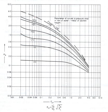
Figure 1: Generalized pressure drop correlation
From Figure 1, K4 = 1.7
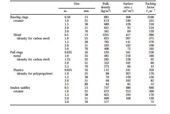
Figure 2: table of design data for various packing [5]
1 inch of ceramic intalox saddles was chosen as packing material. [5] The Packing factor Fp is 300 m-1 from figure 2.
Gas mass flow rate Vm:
k4*ρg* (ρl-ρg) 13.1*Fp*μlρl0.10.5=1.7*1.26* (1000-1.26) 13.1*300*0.0008910000.10.5=1.48 kg m-2 s-1
Area:
GinVm=0.5681.48=0.384 m2
Diameter:
Area*4π0.5=0.384*4π0.5=0.700 m
2.2.1.2 Calculation of height of scrubber [10]
The following parameters were input:
gas inlet flow rate = Gin = 2046.25 kg/h = 4511.21 lb/h
Volume coefficient, gas = KGA = 19 lb.mol/(h.ft3.atm)
Gas molar rate Gin:
Gin*(1-x1)Average molecular weight of entering gases+Gin*x1molecular weight of HCl
=4511.21*(1-93.8%)40.0071+4511.21*93.8%36.5=122.92 lb mol h-1
Liquid inlet flow rate Lin:
1+LG*Gin*LGmin=1+60*4511.21*0.0258=193.43 lb mol h-1
Gas outlet rate Gout:
Gin*(1-x1)(1-x2)=122.92*(1-93.8%)1-13.1%=8.77 lb mol h-1
Moles:
Lin*y1+Gin*x1-Gout*x2=193.43*0%+122.92*93.83%-8.77*13.1%=114.15
Liquid effluent concentration x3:
molesLin*moles*(1-y1)=114.15193.43*114.15*(1-0%)=0.00517
Liquid effluent molar flow rate, L1:
=Gin+Lin-Gout=122.92+193.43-8.77=307.58 lb mol h-1
Gas molar velocity Gm:
Gin+Gout2*Area=122.92+8.772*0.3840.30842=15.91 lb mol ft2 h-1
Gas equilibrium at bottom, y1*:
x3*Henry law constant=0.00517*0.03=0.000155
Gas equilibrium at top, y2*:
y1*Henry law constant=0%*0.03=0
LM Driving Force, (y – y*)LM:
x1-y1*x2-y2*lnx1-y1*x2-y2*=93.8%-0.00015513.1%-0ln93.8%-0.00015513.1%-0=0.410
LM Driving Force, (1 – y*)LM:
1-x11-y1*ln1-x11-y1*=1-93.8%1-0.000155ln1-93.8%1-0.000155=0.337
Number of gas phase unit NOG:
x1-x2(y-y*)LM=93.8%-13.1%0.41=1.97≈2
Height of each gas phase unit HOG:
GmKGA*(1-y*)LM=15.9119*0.337=2.48 ft=0.757m
Length of liquid redistributor between bed = 0.1m=0.328ft
Packed Height Z:
NOG*HOG+length of liquid redistributor=2*2.48+0.328=5.29 ft=1.614 m
Allowance of liquid distribution = 1m
Allowance of liquid redistribution = 1m
Therefore, the Total column height = 1.614+1+1 = 3.614 m
2.2.1.3 Calculation of % flooding [5]
From Figure 1, K4 at flooding = 5.7
% flooding:
100*K4K4 flooding0.5=100*1.75.70.5=54.6%
2.2.1.4 Calculation of fluid velocity with standard pipe size and nozzle diameter
With diameter of 0.7m which is around 27 inch, pipe size data of 30inch adsorption tower was chosen from Figure 3. The diameter of water inlet pipe is 1.5 inch (0.038m) and gas inlet, gas outlet, water outlet pipe is 12 inch (0.305m) [11]
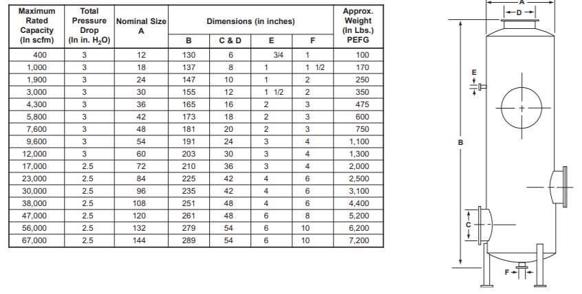
Figure 3: dimension of packed tower [11]
Water inlet volumetric flow rate:
Linρl=0.4031000=0.000403 m3s-1=6.39 gpm
Water inlet velocity:
Liquid inlet volumetric flow rateArea=0.0004030.03822*π=0.353 m s-1
Gas inlet volumetric flow rate = 0.452 m3/s = 7170.842 gpm
Gas inlet velocity:
Gas inlet volumetric flow rateArea=0.4520.30522*π=6.20 m s-1
Density of HCl = 1.49 kg/m3
Liquid outlet volumetric flow rate:
Liquid inlet volumetric flow rate+ Gin*x1*efficiencyDensity of HCl*molcular weight of HCl
=0.000403+0.0142*93.8%*99%1.49*36.5=0.324 m3s-1=5129.663 gpm
Liquid outlet velocity:
Liquid outlet volumetric flow rateArea=0.3240.30522*π=4.44 m s-1
Gas outlet volumetric flow rate:
gas inlet volumetric flow rate- Gin*x1*efficiencyDensity of HCl*molcular weight of HCl
0.452-0.0142*93.8%*99%1.49*36.5=0.129 m3s-1=2047.566 gpm
Gas outlet velocity:
Gas outlet volumetric flow rateArea=0.1290.30522*π=1.77 m s-1
For the calculation of nozzles diameter, the following equation is used:
Qn=28.9*D2*P0.5
Where Qn is the flow rate of fluid (gpm),
D is the diameter of nozzles (inch) and
P is the pressure of fluid (psi) [12]
Pressure of all streams = 1 bar = 14.503 psi
Diameter of nozzle of water inlet:
6.3928.9*14.5030.50.5=0.241 inch=0.006m
Diameter of nozzle of gas inlet:
7170.84228.9*14.5030.50.5=8.07 inch=0.205m
Diameter of nozzle of water outlet:
5129.66328.9*14.5030.50.5=6.83 inch=0.173m
Diameter of nozzle of gas outlet:
2047.55628.9*14.5030.50.5=4.31 inch=0.110m
2.2.1.5 Calculation of wall thickness [5]
Pressure of column = 1 bar = 0.1 N/mm2
Design pressure of column Pi = 0.1*1.1= 0.11 N/mm2
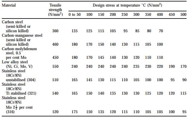
Figure 4: Typical design stress for plates [5]
Since stainless steel 18Cr/8Ni Ti stabilized is chosen as the building material and the temperature of gas inlet is 110OC, the design stress f is 150 N/mm2
The welded joint stress factor J is assumed to be 1
Wall thickness of sphere column:
Pi*D2*f*J-Pi=0.11*0.7*10002*150*1-0.11=0.257mm
The wall thickness was then rounded up and plus 2. Therefore, the actual wall thickness = 1+2 = 3mm
Wall thickness of hemispheric head and bottom:
Pi*D4*f*J-1.2*Pi=0.11*0.7*10004*150*1-1.2*0.11=0.128mm
The wall thickness was then rounded up and plus 2. Therefore, the actual wall thickness = 1+2 = 3mm
2.2.2 Calculation of the second scrubber
2.2.2.1 Calculation of diameter [5]
First, the following parameters were input:
gas inlet flow rate = Gin = 278.397 kg/h = 0.0773 kg/s
Average molecular weight of entering gases = 36.83 Kg/kmol (from Aspen)
Gas molar flow rate Gin = 0.0773/36.83 = 0.0021 kmol/s
Temperature of gas inlet = T=110 oC = 383K
Pressure of gas inlet = P= 0.987 atm
Composition of HCl in gas inlet = x1 = 82.2%
Molecular mass of HCl = 36.5 Kg/kmol (NIST)
Henry constant of HCl = 0.03 [10]
Efficiency of scrubber = 99%
Concentration of HCl in water inlet y1 = 0%
Density of water ρl = 1000 kg/m3
Water viscosity µl = 0.89 Cp = 0.00089 Ns/m2
Gas volumetric flow rate:
Gin*T273*1P*22.4=0.0021*383273*10.987*22.4=0.0669 m3 s-1
Gas density:
ρg=0.07730.4520.0669=1.157 kg m-3
Component removed:
Gin*x1*molecular mass of HCl=0.0021*82.2%*36.5=0.063 kg s-1
Equilibrium constant:
x1Henry constant of HCl=82.2%0.03=27.4
Composition of HCl in gas outlet x2:
Gin*x1*efficiencyGin*1-x1+Gin*x1*efficiency
0.0021*82.2%*99%0.0021*1-82.2%+0.0021*93.8%*99%*100%=4.41%
Slope of equilibrium curve, (L/G)min:
x2-x1y1-equilibrium constant=4.41%-82.2%0-27.4=0.0284
The L to G ratio is assumed to be 60 [9]
Liquid inlet flow rate Lin:
1+LG*Gin*LGmin=1+60*0.0021*0.0284=0.0226 kg s-1=81.2058 kg h-1
Liquid outlet flow rate Lout:
Lin+Gin*x1*efficiency*molecular weight of HCl
=0.0.0226+0.0021*93.8%*99%*36.5=0.0849 kg s-1=305.7296 kg h-1
Gas outlet flow rate Gout:
Gin-Gin*x1*efficiency*molecular weight of HCl
=0.568+0.014*93.8%*99%*36.5=0.0150 kg s-1=53.87303 kg h-1
Liquid-Vapour flow factor FLV:
LinGin*ρgρl0.5=0.02260.0021*1.1510000.5=0.01
The pressure drop of packing was assumed to be 40 mm of H2O /m of packing. [5]
From Figure 1, K4 = 3
0.5 inch of ceramic intalox saddles was chosen as packing material. [5] The Packing factor Fp is 660 m-1 from figure 2.
Gas mass flow rate Vm:
k4*ρg* (ρl-ρg) 13.1*Fp*μlρl0.10.5=3*1.15* (1000-1.15) 13.1*660*0.0008910000.10.5=1.27 kg m-2 s-1
Area:
GinVm=0.07731.27=0.0608 m2
Diameter:
Area*4π0.5=00608*4π0.5=0.278 m
2.2.2.2 Calculation of height of scrubber [10]
The following parameters were input:
gas inlet flow rate = Gin = 278.397 kg/h = 613.76 lb/h
Volume coefficient, gas = KGA = 19 lb.mol/(h.ft3.atm)
Gas molar rate Gin:
Gin*(1-x1)Average molecular weight of entering gases+Gin*x1molecular weight of HCl
=613.76*(1-82.2%)36.83+613.76*82.2%36.5=16.79 lb mol h-1
Liquid inlet flow rate Lin:
1+LG*Gin*LGmin=1+60*613.76*0.0284=10.01 lb mol h-1
Gas outlet rate Gout:
Gin*(1-x1)(1-x2)=16.79*(1-82.2%)1-4.41%=3.126 lb mol h-1
Moles:
Lin*y1+Gin*x1-Gout*x2=10.01*0%+16.79*82.2%-3.126*4.41%=13.66
Liquid effluent concentration x3:
molesLin*moles*(1-y1)=13.6610.01*13.66*(1-0%)=0.1
Liquid effluent molar flow rate, L1:
=Gin+Lin-Gout=16.79+10.01-3.126=23.67 lb mol h-1
Gas molar velocity Gm:
Gin+Gout2*Area=16.79+3.1262*0.06080.30842=15.20 lb mol ft2 h-1
Gas equilibrium at bottom, y1*:
x3*Henry law constant=0.1*0.03=0.003
Gas equilibrium at top, y2*:
y1*Henry law constant=0%*0.03=0
LM Driving Force, (y – y*)LM:
x1-y1*x2-y2*lnx1-y1*x2-y2*=82.2%-0.0034.41%-0ln82.2%-0.0034.41%-0=0.265
LM Driving Force, (1 – y*)LM:
1-x11-y1*ln1-x11-y1*=1-82.2%1-0.003ln1-82.2%1-0.003=0.475
Number of gas phase unit NOG:
x1-x2(y-y*)LM=82.2%-4.41%0.265=2.93≈3
Height of each gas phase unit HOG:
GmKGA*(1-y*)LM=15.2019*0.475=1.68 ft=0.513m
Length of liquid redistributor between bed = 0.1m=0.328ft
Packed Height Z:
NOG*HOG+length of liquid redistrubutor*2=3*1.68+0.328*2=5.71 ft=1.739 m
Allowance of liquid distribution = 1m
Allowance of liquid redistribution = 1m
Therefore, the Total column height = 1.539+1+1 = 3.739 m
2.2.2.3 Calculation of % flooding [5]
From Figure 1, K4 at flooding = 8
% flooding:
100*K4K4 flooding0.5=100*380.5=61.24%
2.2.2.4 Calculation of fluid velocity with standard pipe size and nozzle diameter
With diameter of 0.278m which is around 11 inch, pipe size data of 12inch adsorption tower was chosen from Figure 3. The diameter of water inlet pipe is 0.75 inch (0.019m) and gas inlet, gas outlet, water outlet pipe is 6 inch (0.152m) [11]
Water inlet volumetric flow rate:
Linρl=0.02261000=0.0000226 m3s-1=0.358 gpm
Water inlet velocity:
Liquid inlet volumetric flow rateArea=0.00002260.01922*π=0.079 m s-1
Gas inlet volumetric flow rate = 0.0669 m3/s = 1059.769 gpm
Gas inlet velocity:
Gas inlet volumetric flow rateArea=0.06690.15222*π=3.67 m s-1
Density of HCl = 1.49 kg/m3
Liquid outlet volumetric flow rate:
Liquid inlet volumetric flow rate+ Gin*x1*efficiencyDensity of HCl*molcular weight of HCl
=0.0000226+0.0021*82.2%*99%1.49*36.5=0.0419 m3s-1=663.8837 gpm
Liquid outlet velocity:
Liquid outlet volumetric flow rateArea=0.04190.15222*π=2.30 m s-1
Gas outlet volumetric flow rate:
gas inlet volumetric flow rate- Gin*x1*efficiencyDensity of HCl*molcular weight of HCl
0.0669-0.0021*82.2%*99%1.49*36.5=0.025 m3s-1=396.2433 gpm
Gas outlet velocity:
Gas outlet volumetric flow rateArea=0.0250.15222*π=1.37 m s-1
For the calculation of nozzles diameter, the following equation is used:
Qn=28.9*D2*P0.5
Where Qn is the flow rate of fluid (gpm),
D is the diameter of nozzles (inch) and
P is the pressure of fluid (psi) [12]
Pressure of all streams = 1 bar = 14.503 psi
Diameter of nozzle of water inlet:
0.35828.9*14.5030.50.5=0.057 inch=0.0015m
Diameter of nozzle of gas inlet:
1059.76928.9*14.5030.50.5=3.10 inch=0.079m
Diameter of nozzle of water outlet:
663.883728.9*14.5030.50.5=2.46 inch=0.062m
Diameter of nozzle of gas outlet:
396.243328.9*14.5030.50.5=1.90 inch=0.048m
2.2.2.5 Calculation of wall thickness [5]
Pressure of column = 1 bar = 0.1 N/mm2
Design pressure of column Pi = 0.1*1.1= 0.11 N/mm2
Since stainless steel 18Cr/8Ni Ti stabilized is chosen as the building material and the temperature of gas inlet is 110OC, the design stress f is 150 N/mm2
The welded joint stress factor J is assumed to be 1
Wall thickness of sphere column:
Pi*D2*f*J-Pi=0.11*0.278*10002*150*1-0.11=0.102mm
The wall thickness was then rounded up and plus 2. Therefore, the actual wall thickness = 1+2 = 3mm
Wall thickness of hemispheric head and bottom:
Pi*D4*f*J-1.2*Pi=0.11*0.278*10004*150*1-1.2*0.11=0.051mm
The wall thickness was then rounded up and plus 2. Therefore, the actual wall thickness = 1+2 = 3mm
2.3 Control strategy
First, the HAZOP was proposed according to parameters pressure, temperature and level and agitation. Next, the p&id was drawn based on the action required in the HAZOP. Finally, the start up and shut down procedures were written in consonance with the control element and valve used in the p&id.
3. Discussion
3.1 Summary table of key design results – Equipment Data Sheet
3.1.1 Summary of first scrubber
Operation:
Table 1: Flow rate of each streams in first scrubber
| gas inlet flow (kg/h) | water inlet flow (kg/h) | gas outlet flow (kg/h) | water outlet flow (kg/h) |
| 2046.25 | 1450.367 | 312.6356 | 3183.981 |
Column data:
Number of gas phase unit: 2
Height of each gas phase unit: 0.757m
Height of packing section: 1.614m
Total height of column: 3.614m
Diameter: 0.7m
% flooding: 54.61%
Wall thickness: 3mm
Building material of column: Stainless steel 18Cr/8Ni Ti stabilized
Pipe data:
Table2: pipe diameter of each streams in first scrubber
| gas inlet | water inlet | gas outlet | water outlet | |
| Pipe diameter (m) | 0.305 | 0.038 | 0.305 | 0.305 |
| Nozzle diameter (m) | 0.205 | 0.006 | 0.173 | 0.110 |
Internal data:
Type of packing: Intalox saddles
Size of packing: 1 inch
Material of packing: Ceramic
Packing arrangement: Random packing
Liquid distributor: Model 136 INTALOX Channel Distributor with Drip Tubes
Liquid redistributor: Model 137 INTALOX Channel Redistributor
Packing support: Model 802 Structured Packing Support Grid
Mist eliminator: B-GON®Mist Eliminators
F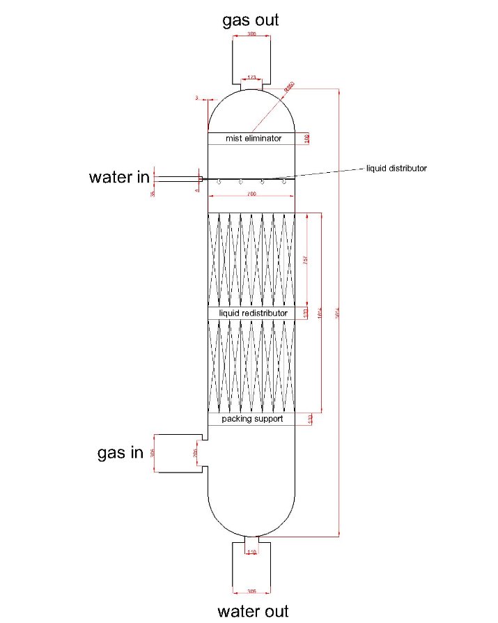 Figure 5: drawing of first scrubber
3.1.2 Summary of second scrubber
Operation:
Table 3: Flow rate of each streams in first scrubber
| gas inlet flow (kg/h) | water inlet flow (kg/h) | gas outlet flow (kg/h) | water outlet flow (kg/h) |
| 278.397 | 81.2058 | 53.87303 | 305.7298 |
Column data:
Number of gas phase unit: 3
Height of each gas phase unit: 0.513m
Height of packing section: 1.739m
Total height of column: 3.749m
Diameter: 0.278m
% flooding: 61.24%
Wall thickness: 3mm
Building material of column: Stainless steel 18Cr/8Ni Ti stabilized
Pipe data:
Table 4: pipe diameter of each streams in first scrubber
| gas inlet | water inlet | gas outlet | water outlet | |
| Pipe diameter (m) | 0.152 | 0.019 | 0.152 | 0.152 |
| Nozzle diameter (m) | 0.079 | 0.0015 | 0.062 | 0.048 |
Internal data:
Type of packing: Intalox saddles
Size of packing: 0.5 inch
Material of packing: Ceramic
Packing arrangement: Random packing
Liquid distributor: Model 136 INTALOX Channel Distributor with Drip Tubes
Liquid redistributor: Model 137 INTALOX Channel Redistributor
Packing support: Model 802 Structured Packing Support Grid
Mist eliminator: B-GON®Mist Eliminators
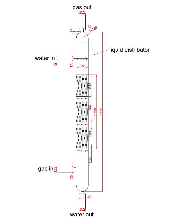 Figure 6: drawing of second scrubber
3.2 Evaluation of obtained result
In the column design section, basic dimension of packed column, piping and nozzles diameter were calculated. Building material and internal apparatus of packed were also decided in the above sections. Therefore, basic design of two scrubbers after the reactors are considered to be finished.
There are two minor problems that need to be taken into account. First, the nozzles diameter of water inlet of second scrubber is only 1.5mm, which is too small when considering piping scale in actual environment. The use of nozzle at that pipe therefore can be abolish according actual situation. Second, Stainless steel 18Cr/8Ni Ti stabilized is chosen the building material of the scrubbers. However, HCl has the ability to attack metal as stated in the section of equipment choice. Further investigation may be required on topic “Is stainless steel the most suitable building material of the scrubbers”.
3.3 Control Strategy, HAZOP and start and shut down procedures
3.3.1 HAZOP
Table 5: Preliminary HAZOP on scrubber
| Guideword | Derivation | Causes | Concequence | Action |
| More | More pressure in packed column | 1.pipe blockage in gas outlet
2. failure of gas inlet valve |
Bursting of columns | High pressure alarm |
| Less | Less flow of water inlet which is in low temperature | Pipe blockage in water inlet | Rapid evaporation of water in column, leading to drying of column and high pressure in column since steam is produced | High temperature alarm |
| More | More flow of water outlet | failure of water outlet valve | Drying of column | Low water level alarm |
| Less | Less flow of water outlet | Pipe blockage of water outlet | Flooding in column | High water level alarm |
| Less | Less mixing time | Failure of water outlet or gas outlet | Desired adsorption cannot be achieved and the efficiency of the column decrease. Undesired product will be produced | Composition analytical element installed in both outlet streams |
| Other than | Other materials besides product from reactors in gas inlet | 1.Leakage of pipes leading to contamination
2. Fouling of reactors, leading to wrong products |
Efficiency of the column may be affected | Composition analytical element installed in gas inlet stream |
3.3.2 P&ID
Water outlet
Water inlet
gas inlet
gas outlet
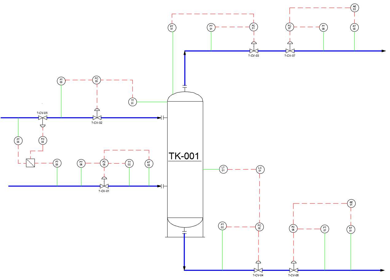
Figure 7: P&ID applied to both scrubbers
Description of P&ID:
- PT01(FT01)-FC01-CV03 cascade control to maintain constant pressure inside the column
- LT01(FT02)-FC02-CV04 cascade control to maintain certain water level inside the column, preventing flooding and drying inside the column
- TT01(FT03)-FC03-CV02 cascade control to maintain constant temperature inside the column. Water in lower temperature have a cooling effect on gases and the column
- FT04(FT05)-FC04-CV05 ratio control to maintain constant liquid to gas ratio
- AT03(TT02, FT06)-FC05-CV01 cascade control to analyses the composition of feed stream (gas inlet)
- AT01(FT07)-AE03(FC06)-CV06 cascade control to analyses the composition of product stream (water inlet)
- AT02(FT08)-AE02(FC07)-CV07 cascade control to analyses the composition of gas outlet
3.3.3 Start up and shut down procedures
Start up procedures:
- Open CV03, CV04, CV06, CV07 to evacuate residue inside the column as much as possible.
- Close all CV after 1 minute.
- Open CV02 and CV05 to allow water going into the column
- Open CV01 after 30 minutes to allow gas going into the column
- Open CV03, CV04, CV06, CV07 when high pressure alarm is alerted or certain water level has reached in the column (level transmitter located according to % flooding of column)
Shut down procedures:
- Close CV01 first to cut gas supply
- Close CV02 and CV05 after 5 minutes to cut water supply
- Wait 10 minutes after cutting water supply to ensure all products has left the packed column
- Close all CV
3.4 Suggested improvements on design and control strategy
There are two errors in design section which may affect the result and further calculation may be required. First, the gas inlet temperature of both scrubbers is 110OC and that of the water inlet is 20OC. Therefore, the operation temperature of the column was assumed to be 50-60OC, which is lower than the boiling point of water. The calculation of mass balance is assumed no water evaporating and going to gas outlet as a result. However, evaporation of water still has the probability to occur. This affects the mass balance in actual environment and the efficiency of the packed column as well. Second, the internal parts, which are the liquid distributor, liquid redistributor, packing support and mist eliminator, are using standard model providing by certain companies. However, neither standard size of these internal equipment nor equation on calculating those can be found. The drawing of dimension of these internal parts is just an estimation as a result and further action may be required to ensure the calculation of both scrubbers.
For control strategy, an improved version of HAZOP can be adapted when combining the HAZOP of other parts throughout the whole production process. Specific temperature and pressure of packed column can also be assigned to have more precise control on the column. Finally, the time estimation in start up and shut down procedures may also be fixed especially for the time for the opening of CV01, which allow gas getting into the packed column.
4. Conclusion
Building material and internal apparatus of packed have been selected for both scrubbers. Basic dimension of packed column, piping and nozzles diameter have also been calculated. Besides, control and safety issues have also been proposed, which are the HAZOP, P&ID and start up and shut down procedure. However, there is a few issues and improvements made on the scrubbers and may need to be followed up in the future.
5. References
- Method of Industrially Producing Monochloroacetic Acid (2017) WO 2017/135832 Al.
- A Process for the Preparation of Monochloroacetic Acid (2011) EP 1,529,604 B1.
- J. Chironna, R. (2011). Wet scrubbing of acidic gases. [pdf] Schutte & Koerting, Available at: https://www.s-k.com/technical-references/wet_scrubbers.pdf [Accessed 18 Nov. 2018].
- ABSORPTION OF HCL, Available at: https://www.dedietrich.com/en/solutions-and-products/mineral-acid-treatment/hydrochloric-acid-treatment/absorption-hcl (Accessed: 5th December).
- R. K. SINNOTT (2005) COULSON AND RICHARDSON’S Chemical Engineering Design, 4th edn.
- Packed Bed Wet Scrubber Design, Available at: https://www.monroeenvironmental.com/air-pollution-control/packed-bed-wet-scrubbers/ (Accessed: 5th December)
- Koch-Glitsch, Packed tower internals [pdf], Available at: http://folk.ntnu.no/skoge/prost/proceedings/distillation10/DA2010%20Sponsor%20Information/Koch%20Glitsch/Packed_Tower/Tower_Internals/Metal_PTI.pdf (Accessed: 5th December).
- Gas Scrubbers & Chemical Scrubbers, Available at: https://www.pollutionsystems.com/chemical-scrubbers-gas-scrubbers.html (Accessed: 5th December).
- Design Evaluation of Particulate Wet Scrubbing Systems [pdf], Available at: https://mycourses.aalto.fi/pluginfile.php/160609/mod_folder/content/0/Design%20Evaluation%20of%20Particulate%20Wet%20Scrubbing%20Systems.pdf?forcedownload=1 (Accessed: 5th December)
- Stephen Hall, Rules of Thumb for Chemical Engineers, 5th edn.
- Schutte & Koerting Gas Scrubbers [pdf], Available at: https://www.s-k.com/pdf/7S_ejector_venturi_scrubbers_brochure.pdf (Accessed: 5th December).
- Nozzle Requirements, Available at: http://irrigation.wsu.edu/Content/Calculators/Sprinkler/Nozzle-Requirements.php (Accessed: 5th December)
- KIMRE B-GON®Mist Eliminators, Available at: http://www.kimre.com/mesh-pad-mist-eliminators/ (Accessed: 5th December)
Cite This Work
To export a reference to this article please select a referencing stye below:
Related Services
View all


Related Content
All TagsContent relating to: "Chemistry"
Chemistry is a science involving the study of the elements and matter at the atomic and molecular level including their composition, structure, properties, behaviour, and how they react or combine.
Related Articles

DMCA / Removal Request
If you are the original writer of this dissertation and no longer wish to have your work published on the UKDiss.com website then please: