Advanced Manufacturing Processes Lab Reports
Info: 4046 words (16 pages) Dissertation
Published: 26th Jan 2022
Tagged: Engineering
Contents
Electrical Discharge Machining (EDM)
Introduction
Basic Structure of Sodick AP3L
Typical Tooling System
Dielectric Type and Flushing Methods
Programming the Sodick AP3L
Conclusion
Electron Beam Machining (EBM)
General Information
The Equipment used
The EBM process
The Parameters of EBM
Electron Beam Process Capability
Fuse Deposition Modelling (FDM)
Introduction
Preparing the STL file for 3D printing
Conclusion
References
Electrical Discharge Machining (EDM)
Introduction
The aim of this report is to convey a good understanding of the electrical discharge machining process in general, as well as to show how the Sodick AP3L EDM machine works and is programmed.
EDM originated from the need to machine more intricate shapes and components as well as to machine certain metals that were previously difficult to machine. EDM is basically a machining process whereby materials that are electrically conductive are machined through electrical discharges known as sparks. It makes use of an electrode, which can be seen as being the cutting tool, that is machined in such a way that it has the opposite form to that needed on the actual workpiece. The machining process then takes place by placing the electrode close to the workpiece but in such a way that it does not actually contact the workpiece. The reason why the electrode does not come into contact with the workpiece is because it needs to maintain a gap known as the sparking gap in order for the sparking process to take place. Otherwise, the sparking would not occur and no material removal would take place [1].
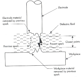
It is interesting to note that only one spark occurs at an instant in time, but the frequency is so large that it seems like many sparks are occurring at once. This spark does not only remove material from the workpiece, but also from the electrode itself. Hence the total distance between the electrode and workpiece is decreased and the next spark occurs at the new place that has the least distance between the electrode and workpiece. The process carries on in this way. Since material is removed through a sparking process, it is evident that the EDM process is a thermal process, where material is removed by the heat of the spark and the material becomes vaporised. A dielectric fluid is needed in order to maintain the sparking gap, as well as to cool down the vaporised material to form a chip. In Die-sinker machines, as is the case of the Sodick machine, this fluid is usually oil. The fluid not only cools down the vaporised material that would have been removed, but it also removes the chips from interfering with the material removal process through sparking. Figure 1(a) on the following page shows how the sparking process takes place initially, whereas Figure 1(b) helps in understanding how the next spark would form once the material shown in part (a) is removed [1].
Basic Structure of Sodick AP3L
The Sodick AP3L machine is a die-sinker type EDM and hence works as was explained in the introduction. It consists of a magnetic chuck that is clamped to the worktable and the workpiece is placed into this magnetic chuck. The inside of this chuck has a lot of magnets that secure the workpiece and this can be controlled by a moving a lever. The worktable itself is ceramic and this means that it won’t expand or contract during machining.
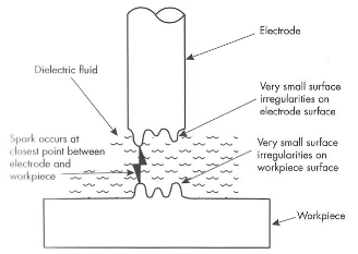
(a) (b)
Figure 1 – EDM Sparking Process[1]
This worktable is then situated inside a tank which contains the dielectric fluid. The electrode is connected to the spindle that is allowed to move up and down as well as rotate from 0 rpm to 2000 rpm in fractions of 360°, according to what is required. In addition, it consists of an automatic tool changer. At the back of this machine, there is a fire sensor and an extinguishing system which is necessary due to safety. Furthermore, there are two cooling units. One is used to cool the motor while the other is used to cool the dielectric fluid. The Sodick AP3L EDM machine situated in the lab can be seen in Figure 2 below.
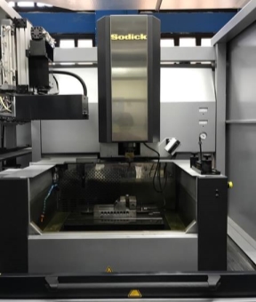
Figure 2- Sodick AP3L
Typical Tooling System
The electrodes that are used are typically machined relatively easily on a vertical machining centre and are usually made out of oxygen free copper. As was mentioned previously, the electrode must have the inverse shape to the shape that is required to be generated on the workpiece.
During the EDM process overcut occurs. In simple terms this is the distance between the electrode and the workpiece’s machined surface after the sparking procedure. Hence when designing the electrode, one must take this overcut into consideration and there must be a clearance due to this overcut. The overcut follows the shape of the electrode and it occurs because the electrode would have sharp corners that produce a corner radius on the workpiece due to the fact that the sparks produced at these corners have the same length and originate from the same point, producing a radius that is the same as the overcut dimension [1].
The electrode can have several different shapes and hence one can produce as many products as required in mass production. Figure 3 below shows one of the intricate shapes (an owl) that can be produced using these tools and the EDM.
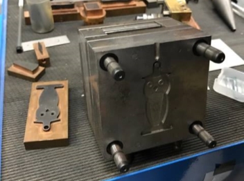
Figure 3- Intricate shapes can be produced
In general, two different electrodes would be used during the machining process. One would produce a rough surface whereas the second is more refined and produces the finished product. One can also make use of graphite electrodes which have very good work characteristics. Their main disadvantage is that they generate a lot of dust and hence this would need to be extracted.
The EDM tool holders give a very precise location of the electrodes. They have four dowels that make the tool holder as concentric as possible to the spindle, to reduce errors. These are tightened with screws. There is also another type of tool holder that has a collet, which means it is a tapered component. It has several slits and its diameter can vary.
Dielectric Type and Flushing Methods
Since the Sodick AP3L is a die-sinking machine, its typical dielectric fluid is oil, which is a hydrocarbon fluid. A dielectric fluid must be an electrical insulator at one point where it would resist the flow of electricity, but it must then be capable of changing into an electrical conductor when the voltage becomes higher. The point at which this change from an insulator to a conductor takes place is known as the ionisation point. It is at this point that the sparking occurs and this is because the dielectric fluid will be conducting the electricity from the electrode to the workpiece. It then changes back to an insulator once the spark would have occurred, and the process is repeated for each spark [1].
One of the functions of this dielectric fluid is that it cools both the electrode and the workpiece by removing the heat generated and keeping them both at a lower temperature, such that when touching them they would only be slightly warm. This dielectric fluid is often cooled in order to ease this process. Previously the process of generating a chip when machining was described, and this occurs because the vaporised material comes in contact with the cool fluid and solidifies to form a chip. The fluid then also helps in removing these chips, as it flows through the sparking gap and the chips are then transferred to a filtration system. In the case of the Sodick machine, this filtering occurs through the use of a paper filter, which gets rid of the chips as well as any other debris. Additionally, it makes sure that the fluid remains clean and acceptable enough to be reused once again. If the pressure becomes too low, the paper filter might become too clogged and this means it would need to be replaced [1].
Programming the Sodick AP3L
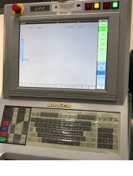
The Sodick AP3L comes equipped with a LP2 series power supply unit which can be programmed to give very high-precision machining at a fast rate. The screen is touch screen, which makes it easy for the user to programme the machine as required. This LP2 series can be seen in Figure 4 below.
Initially the correct conditions must be set. The datum is set as being the top surface of the workpiece. The x, y and z directions are established. The material of the electrode as well as the workpiece is chosen; typically, these are copper and steel respectively. The projected area of the electrode is then chosen. Additionally, the roughness is also set.
There are five different choices of performance speed. Increasing this performance speed also increases the amount of wear. Hence if this performance speed is lowered, the wear is also reduced. The first option would give a rough surface, whereas the second would be a semi-finish, with the third option giving the best finish.
With regards to pressing, the best undersize must be chosen. This is given as 0.14mm. One must also select the loran pattern. This could be angular, round, square, spherical, amoungst many others, according to the desired shape. The taper angle, if required, can also be selected. When selecting the current, one must keep in mind the depth of the cut required. This is because by increasing the current, one would be increasing the depth of the cut.
To conclude, all the necessary conditions can be selected using this touch-screen programme and hence the machining process is easier to control.
Conclusion
Die-sinker EDM machines like the Sodick AP3L machine found in the lab are typically used to produce three-dimensional shapes that might be difficult to produce using conventional machining processes [1]. The advantages of using an EDM include the fact that tolerances of about 0.005 can be attained, that complex and difficult shapes can be produced which could not be produced by conventional methods, and that since the electrode does not come into contact with the workpiece, no cutting forces are produced, and this means that very delicate parts can be machined using the EDM since no forces would affect them. On the other hand, EDM can only be used to machine materials that are conductive, and in addition is more expensive than typical conventional machining processes such as milling or turning [2].
Electron Beam Machining (EBM)
General Information
Electron Beam Machining (EBM) is a thermal process considering the mechanisms of material removal. This is achieved by using electrical energy to generate high-energy electrons, which makes the process classified as an electro-optical-thermal process or as a thermal beam process.
The EBM Process normally has an active diameter in the tune of tens of microns up to millimetres, which is dependent on how focused the beam is by the operator. The power density used by the EBM is also dependant on how focused the beam is, as it could range anywhere from as low as 1W/mm2 to tens of thousands of Watts per millimetre squared [3]. Thus, the EBM is typically used with higher power densities so as to properly machine materials, as the primary method of material removal via the EBM is by melting via the intense heat given off by the electrons.
The Equipment used
In the figure below, one can see the schematic of an Electron Beam Gun. The basic concept of this gun is that it generates free electrons at the cathode, which are then accelerated to a high enough velocity only to be then focused over a small spot size. The cathode is usually made out of tungsten or tantalum to generate and resist the high operating temperatures in the tune of 25000ᴼC in the gun [3]. To further aid the thermo-ionic electron emission of the cathode, a very low vacuum is maintained to prevent any collisions experienced by the electrons and the cartridge is negatively biased to repel the electrons faster.
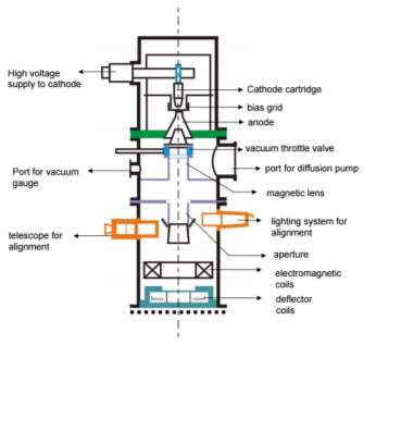
Just below the cathode, one can see an annular bias grid. This grid is used to converge the electrons of the cathode into a beam. This is achieved by introducing a negative bias to the said grid. The newly generated beam is then gradually accelerated using the anode directly below the bias grid via the forces of attraction. Since the biasing grid is used to generate the beam, many models tend to use the bias grid as a form of switch to generate a pulsing beam of electrons. Having passed through the anode, the beams passed through a series of magnetic lenses and apertures to shape, converge and filter the beam to improve the quality of the beam. Having done all of this, the electron beam soes through the final section of the electromagnetic lens and deflection coil which focus and manage the beam respectively, increasing the focus and improving the shape of the holes produced.
To help protect the gun from metal fumes and vapor, a series of slotted rotating disks are placed in vacuum between the electron beam gun and the workpiece. Another useful accessory for electron beam guns include an illumination facility and a telescope. As one might guess, their use is to ensure that the EBM’s beam is aligned correctly to the workpiece. In the case that numerous holes are needed to be machined into the part, the workpiece is usually mounted on a CNC table to facilitate ease of control for the operator via inputting G codes or other forms of CNC control.
As previously mentioned, a very important requirement of the EBM operation is the maintenance of the vacuum in the electron beam gun. The level of pressure upheld in the above mentioned apparatus is in the tune of 10-4mm of mercury or 10-6mm of mercury depending on the requirements of the part [3]. The vacuum is usually maintained via a combination of rotary and diffusion pumps. Adhering to this level of vacuum is critical to the EBM operation as upon colliding with air molecules and dust, the electrons will lose their energy whilst also reducing the life of the cathode cartridge.
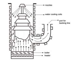
The diffusion pump, as seen in the below figure, is attached to the diffusion pump port of the electron beam gun as seen in the electron beam gun schematic in the previous page. Simply put, the diffusion pump is an oil heater. Once the oil is heated to the vapour state, it goes up the system seen in the below figure. The nozzles present will then change the direction of the oil flow as indicated in the diagram as a jet, trapping the air molecules that were present in the gun, which is then evacuated via the backing line, allowing the oil to condense via the water cooling coils around the pump.
The EBM process
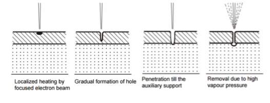
As seen in the above section, an electron beam is generated in an electron beam gun. The electron beam is not to be exposed to air molecules as upon interaction, the electrons would lose energy, thus losing their cutting ability. To combat this, the workpiece to be machined is placed under the electron beam and is kept under vacuum. The usual cutting diameter of the high-energy density beam is in the tune of 10 – 100 μm [3]. As seen in the below figure, the kinetic energy from the electron beam is converted to heat energy upon hitting the work material, causing the material to instantly melt via the high-power density of the beam. Once this is done, the molten material is then expelled from the work area via the high vapor pressure.
Unlike the Electron Beam Welding process, the electron beam used in the EBM process is a pulsed beam. This is especially true when drilling holes using the EBM as when drilling in thin sheets of materials, only a single pulse is required, whilst for thicker plates, numerous pulses are used.
The Parameters of EBM
The main parameters that directly effect the EBMs machining characteristics are:
- The accelerating voltage
- The beam current
- Pulse duration
- Energy per pulse
- Power per pulse
- Lens current
- Spot size
- Power density
As previously mentioned, the electron beam gun is used in pulse mode via introducing a negative bias to the biased grid just below the cathode cartridge. These pulses can range from 50 μs to as long as 15 ms [3]. By definition current is the flow of electric charge (or rather electrons) per unit time, and thus the beam current is related to the number of electrons in the beam. Beam current can usually be seen in the tune of between 200 μamp to 1 amp [3]. This parameter, along with pulse duration, increases the energy per beam pulse.
Two important factors in the EBM operation are the energy density and the power density. These two factors are effected by the energy per pulse duration and the spot size. The spot size is in turn regulated via the degree of focusing achieved by the electromagnetic lenses. As one can imagine, the higher the energy density, the material removal rate would be higher, with the trade-off being that a smaller hole is generated.
Electron Beam Process Capability
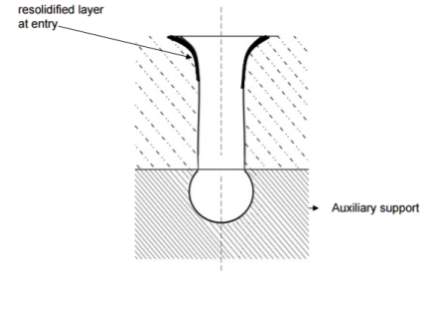
The EBM system can machine holes of diameters in the tune of 100 μm to 2 mm and a depth of approximately 15mm [3]. From the figure below, one can see a typical hole drilled by the EBM. Using the EBM process, it is also possible to generate a taper or even a reverse taper to the hole. These tapers can be generated by manipulating the focus of the electron beam. Upon generating the hole, an edge rounding at the entry point as well as a recast layer are generated as seen in the below figure.
Since the EBM process is not a mechanical process, but a thermal beam process, many materials ranging from polymers to ceramics can be successfully machined. Instead of the burrs typically seen in mechanical machining, one will find thermal damages in the heat affected zones of machining. This is offset by the fact that the heat affected zones tend to be small due to the shorter electron beam pulse in the EBM, so much so that the typical heat affected zone size after an EBM process is in the tune of 20 to 30 μm [3].
It is also important to note that since the EBM process is not a mechanical process, but a thermal beam process, the EBM does not generate any cutting forces whilst machining. This means that not only can a very simple work holding be enough, but also, fragile and brittle materials are machinable on the EBM.
Fuse Deposition Modelling (FDM)
Introduction
The fused deposition modelling (FDM) process generates parts by extruding material (usually a thermoplastic polymer) through a spout that travels in the X and Y axis in order to create each two-dimensional layer. In each layer, separate nozzles extrude and deposit material that create the parts and material that generate supports where required made out of a soluble material [4]. The particular model of machine being used in the lab is a Dimension 1200, which typically uses acrylonitrile butadiene styrene (ABS). The Dimension 1200 uses a rod of ABS about 2mm in diameter which is extruded through a hot nozzle which reduces the size of the rod to about 0.25-0.33mm in diameter. Moreover, it uses a heated environment of about 300ᵒC in order to reduce the stresses developed within the soluble supporting material used.
Preparing the STL file for 3D printing
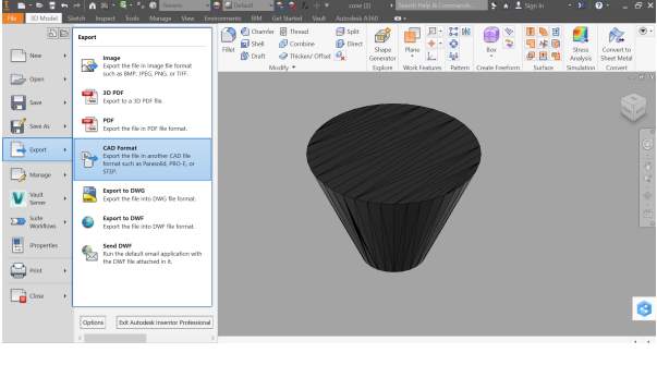
The cone.stl file was first downloaded and then opened using Autocad Inventor. The file was then exported (using Export, CAD Format) as an STL file, as shown in figure 9.
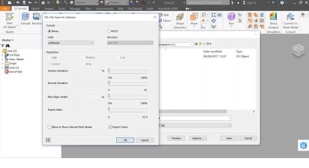
The units were made sure to be set to millimetre using the options tab before exporting to STL format, as shown in figure 10.
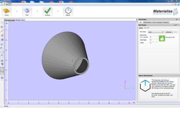
The file was then saved onto a thumb stick and opened on the computer in the lab using MiniMagics. Minimagics was used in order to check if the part had any defects as shown in figure 11.
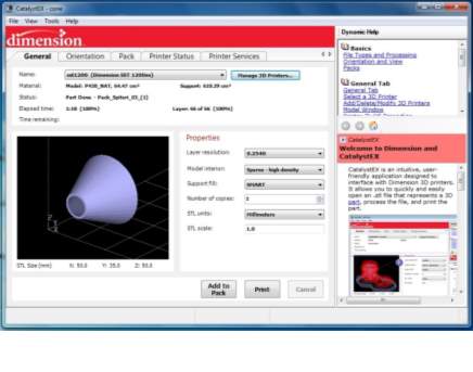
CatalystEX software was opened and the file was dragged and dropped into it, as shown in figure 12.
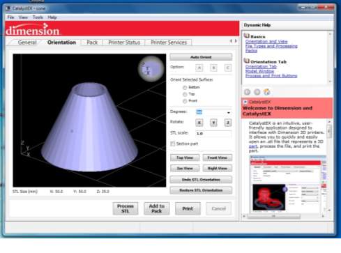
The orientation tab was opened and the top face, shown in figure 13 below was chosen to be set as the top face by first clicking on the top face and then clicking on the Top view button.
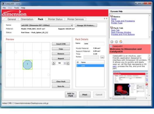
The pack tab was then opened and the Add to Pack button was clicked on in order to set the part onto the floor of the printer, as shown in figure 14. If the part was to be printed the Print button would be clicked on in order to print the part.
Conclusion
Common applications of fuse deposition modelling comprise: rapid prototyping, manufacturing aids, jigs and fixtures, low volume production, and carbon fibre layup tooling [5]. FDM offers an extensive range of thermoplastics, has no need for any post curing, offers easy material change over, and low end, economical machines can perform it. However, FDM is not ideal for small structures, details, and thin walls. Moreover, FDM does not give the best surface finish, is slow on large or dense parts, and support material integration and removal is fairly difficult [6].
References
[1] Jameson EC. Electrical discharge machining. Society of Manufacturing Engineers, Machining Technology Association; 2001.
[2] Advantages and Disadvantages EDM – EDM Precision n.d. http://edmprecision.com/advantages-and-disadvantages-edm/ (accessed April 10, 2017).
[3] Module 9 Non conventional Machining Lesson 40 Electron Beam and Laser Beam Machining n.d.
[4] Hopkinson N (Neil), Hague RJM, Dickens PM. Rapid manufacturing : an industrial revolution for the digital age. John Wiley; 2006.
[5] Fused Deposition Modeling | Solutions | Stratasys Direct Mfg n.d. https://www.stratasysdirect.com/solutions/fused-deposition-modeling/ (accessed April 30, 2017).
[6] Rapid Prototyping Techniques, Selective Laser Sintering, 3D Printing & FDM Prototype Mumbai n.d. http://www.protosystech.com/rapid-prototyping.htm (accessed April 30, 2017).
Cite This Work
To export a reference to this article please select a referencing stye below:
Related Services
View all


Related Content
All TagsContent relating to: "Engineering"
Engineering is the application of scientific principles and mathematics to designing and building of structures, such as bridges or buildings, roads, machines etc. and includes a range of specialised fields.
Related Articles

DMCA / Removal Request
If you are the original writer of this dissertation and no longer wish to have your work published on the UKDiss.com website then please: