Die Fixture of an Underwater Pelletizer for a Waste Disposal and Recycling Company
Info: 8734 words (35 pages) Dissertation
Published: 9th Dec 2019
Tagged: Engineering
Abstract
The topic chosen by the student for this project is the redesigning of a die for an underwater pelletizing machine. The machine is used by a waste disposal and recycling company. The company uses the pelletizer to produce High Density Polyethylene (HPDE) pellets from recycled waste HDPE. The student chose this topic because the owner of the company is friend of the family. It was found that the pelletizer was not producing the amount of material it is capable of producing. The main objectives of this project are to redesign the die of the pelletizer, improve the productivity of the pelletizer and manufacture the die.
Symbols/Nomenclature
Symbol Unit Description
psi Pounder-per-square inch Pressure
mm millimetres Length
Kg Kilogram Mass
$ US Dollars Currency
Ρ mass per volume (kg/m3) Density
oC Degrees Celsius Temperature
c Cent(s) Currency (Euro)
€ Euro(s) Currency (Euro)
“ inch Length
Ft Feet Length
Ft/sec Feet –per-second Velocity
m Metre Length
m/s metres-per-second Velocity
lb(s) pounds Mass
oF Degrees Fahrenheit Temperature
A squared metres Area
r metres Radius
π N/A (Constant) pi
m’ mass-per-unit time Mass flow rate
q’ volume-per-unit time Volumetric flow rate
V’ distance-per-unit time Velocity
S revolutions-per-unit time Angular velocity
L metres Length
V cubic metres Volume
M Kilograms Mass
Glossary
WERS Wheely Environmental Refuse Services
HDPE High Density Polyethylene
PP Polypropylene
PCD Polycrystalline Diamond
RTV Room Temperature Vulcanizing
SSE Single Screw Extruder
TSE Twin Screw Extruder
LDPE Low Density Polyethylene
NIR Near Infrared Radiation
RPM Revolutions Per Minute
RPS Revolutions Per Second
Table of Contents
2. Chapter Two – Literature Review
2.1. History of Polymer Processing
2.1.4. Physical Properties of HDPE
2.3. Product – Crown Underwater Pelletizer
2.4.2. Possible Die Design Solutions
3. Chapter Three – Materials and Methods
3.1.2. Removing the Countersink Bolts
4. Chapter Four – Work done to-date
5. Chapter Five – Preliminary Results
5.1. Velocity and Flow of the Material
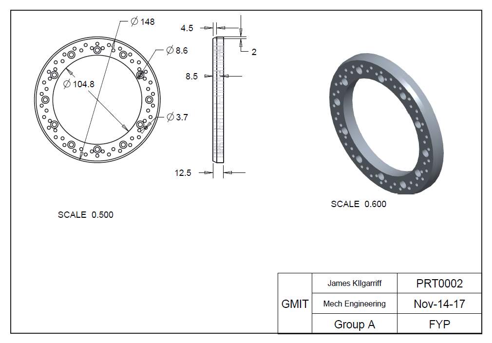
Appendix A: CAD Drawing of Current Die Ring
Table of Figures
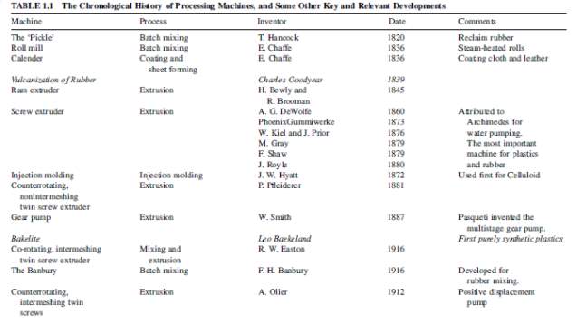
Figure 2‑1 History of Polymer Processing Machines (1820-1916) (Gogos & Tadmor, 2014)
Figure 2‑2 History of Polymer Processing Machines (1935-1979) (Gogos & Tadmor, 2014)
Figure 2‑3 Bottle and Containers (WERS Waste)……………………. Figure 2‑4 Pellets from Recycled Plastic
Figure 2‑5 WERS Lorry (WERS Waste Donegal)
Figure 2‑6 Anti-Turbulent Water Chamber (Crown)
Figure 2‑7 Cutter Hub with six 4-edged blades (Crown)
Figure 2‑8 Diverter Valve (Crown)
Figure 2‑9 Magnetic Clamp (Crown)
Figure 2‑10 Example of Die Hole Freeze-off
Figure 3‑1 Current Die Ring (Shattered)
Table of Tables
Table 4‑1 Figures & Data from Pelletizer
List of Equations
Equation 4‑2 Total available area in the die
Equation 4‑3 Mass flow rate of polymer per second
Equation 4‑4 Volumetric flow rate of polymer
Equation 4‑5 Velocity of polymer
Equation 4‑6 Speed of pelletizer per second
Equation 4‑7 Number of cuts per second
Equation 4‑9 Number of holes in a die
Equation 4‑10 Volume of a pellet
Equation 4‑11 Mass of a pellet
Equation 4‑12 Ideal number holes in die for 350 kg/hr
Equation 5‑1 Mass flow rate per hole
Equation 5‑2 Average mass flow rate for 3.2 mm die hole
Equation 5‑3 Minimum Optimal Mass Flow Rate
1. Chapter One – Introduction
1.1. Introduction
WERS (Wheely Environmental Refuse Services) Waste is a waste disposal and plastic recycling company in Tuam, Co. Galway. It was founded in 1989 by the Gleeson brothers, Pat, Martin and Paul. They were the first providers of the wheelie bin service which is now available all over Ireland. Their catchment area includes North Galway, South Mayo and South Roscommon. As well as pioneering the wheelie bin service, it was also the first private contractor to provide a compost facility to householders in Tuam (Waste Waste Tuam Wers Tuam County Galway Wers Recycling Tuam County Galway WERS Refuse Collection Tuam, no date)
The company uses an Underwater Pelletizer to produce plastic pellets from recycled waste. The plastic is forced out through a die by a double rotating screw and rotating blades slice the plastic into pellets which are then forced out by water. The problem is with the die. The die ring is held in place in the die head by M5 countersunk screws. Over time the blade wears into the die ring and can damage the head of the screws. In order to remove the die ring, the damaged screws have to be drilled and tapped out.
Another problem with the pelletizer is the amount of pressure. The pressure in the extruder is limited to approximately to 3500 psi and can’t go below 500 psi. When the twin screw began to wear over time, the pressure to force the material through the die dropped. This pressure drop caused a back flow of plastic. Because of the backflow, less material was passing through the die ring. The twin screws were refurbished with flights of increased pitch, which has increased the pressure at the die head. The current die head contains 54 holes at a diameter of 3.2 mm.
The company feel that if the number of die holes is increased, the pressure at the die head will drop, so enabling the speed of the extruder to be increased, therefore increasing the output of the pelletizer and improving production.
1.2. Aims and Objectives
The following is a list of problems that WERS Waste want to fix in relation to the underwater pelletizer as well as some personal objectives in relation to project.
- Redesign the removal of the die ring by eradicating the countersink screw.
- Implement the correct number of holes in the die ring.
- Increase the mass flow rate of material from 350kg/hr.
- To investigate various materials for the die ring.
- To investigate the relationship between the screw speed and the mass flow rate of material.
- Manufacture a new die head and die ring.
2. Chapter Two – Literature Review
The following is the background research and literature review conducted by the student. The literature review outlines the history of polymer processing from its beginning’s during the industrial revolution, the history of HDPE, its properties and the importance of recycling it. Also outlined is the product itself; the Crown Underwater Pelletizer and its different components. Design constraints are also outlined. This information in this chapter was taken from some journals and books, but because of the lack of journals in this field, some websites had to be referenced as well.
2.1. History of Polymer Processing
The following is a brief description of polymer processing, its beginnings in the 19th century, the history of HDPE, its properties and how it is recycled. Also outlined is the importance of recycling HDPE and plastic in general.
2.1.1. 19th Century
The 19th century was a period in history known as the “Industrial Revolution”. This was a period of great innovation and some of the first great technological advancements took place during this time. The Industrial Revolution in Britain can be viewed in two ways. The first is that it was the broad change in the British economy and society. The other view is that it was the technical changes in a few industries, a much smaller phenomenon (Temin, 1995).
It was during this period where there was a huge interest and advancement in the processing of polymers (i.e. plastics). Polymer processing is “the engineering activity concerned with operations carried out on polymeric materials or systems to increase their utility”. In other words, this is the conversion of the raw polymeric materials into finished products. Polymer Processing is not only shaping of the polymer but also the “compounding and chemical reactions leading to macromolecular modifications and morphology stabilisation, and thus, ‘value added’ structures” (Gogos and Tadmor, 2014).
Polymer Processing is closely related to rubber processing. The first mention of a rubber- processing machine is from 1820. Thomas Hancock designed a machine he called the “pickle” which was a rubber masticator that consisted of a toothed rotor turned by a winch inside a toothed cylindrical cavity. It was used to reclaim scrap rubber which was an early form of recycling. In 1836, Edwin Chaffe from Roxbury, Massachusetts developed both the two-roll mill and the four-roll calendar for mixing additives into rubber and for continuous coating of cloth and leather by rubber respectively (Gogos and Tadmor, 2014).
In 1845, Henry Bewley and Richard Brooman invented the first extruder in England. This device produced the first submarine cable, which was laid between Dover and Calais (1851) as well as the Anglo-American cable (1860). The need to produce continuous wire led to the most important advancement in the processing field, which was the Single Screw Extruder (SSE). A.G. De Wolfe in the United States may have produced the first SSE in the 1860 but this has not been confirmed. There are many SSE examples throughout the 1860s and 1870s but the first clear patented example is from Michael Gray, England, in 1879. His design included a pair of heated rolls, which was a first. Two more men invented their own SSE’s around this time. They were Francis Shaw in England and John Royle in the United States (Gogos and Tadmor, 2014).
A very important figure in the development of injection moulding was John Hyatt from Boston. He invented a thermoplastics injection moulding machine in 1872. He design was based on the idea of metal die-casting used before. He was the man that produced celluloid, for replacing ivory in billiard balls as part of a $10,000 challenge award. He also contributed to innovations in blow molding (Gogos and Tadmor, 2014).
Paul Pfleider invented the nonintermeshing, counterroating, twin screw extruder (TSE) in 1881. Pfleider’s machine was the basis for further advancements in the 20th Century such as R.W. Eastons co-rotating machine in 1916, and A. Olier’s positive displacement counterroating machine in 1921 (Gogos and Tadmor, 2014).
One of the last major innovations of the 19th century in terms of polymer processing was the introduction of Gear Pumps by Willoughby Smith in 1887. This innovation allowed the processing machine to be fed by a pair of rolls. These advancements in the processing of polymers laid the path for those of the 20th century where extrusion was the main focus.
2.1.2. 20th Century
At the turn of the century, rubber mixing became quite an unpleasant task. It involves mixing fine carbon black particles with other additives which was done on open rolls. Then, the first improved ‘internal’ mixer was developed and patented by Fernley. H. Banbury. His design which was developed by The Birmingham Iron Foundry in Derby, Connecticut is still used to this day (Gogos and Tadmor, 2014).
The design of the modern day injection molding machine came about in 1952. It was designed by W.H. Wilert. This design greatly improved the breadth and quality of injection molding. Many ideas that were put forward in the fifties were Maxwell and Scalora’s screw less extruder. The principle of this idea was to use two disks closely positioned and rotating with one having an opening in the center. The normal stress difference and centripetal forces pumped the material toward the opening (Gogos and Tadmor, 2014).
 Finally, Zehev Tadmor developed the co-rotating disk processor which he called ‘Diskpack’ (Gogos and Tadmor, 2014). Throughout the last 150 years there have been huge advancements in polymer processing. Most of the innovations took place between 1850 and 1950, but even today there are still advancements being made.
Figure 2‑1 History of Polymer Processing Machines (1820-1916) (Gogos & Tadmor, 2014)
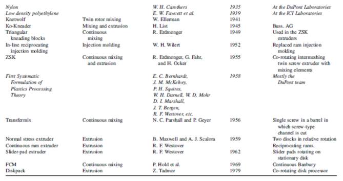
Figure 2‑2 History of Polymer Processing Machines (1935-1979) (Gogos & Tadmor, 2014)
2.1.3. History of HDPE
High-Density Polyethylene, HDPE was first created in 1953 by Karl Ziegler and Erhard Holzkamp. It was achieved by using catalysts and low pressure which was previously how polyethylene compounds were formed. Then in 1955, HDPE was first used to produce piping. In terms of drainage, HDPE is the most common plastic used. Its applications include storms sewers, perforated underdrains, storm drains, slope drains, cross drains and culverts (Gabriel, no date).
2.1.4. Physical Properties of HDPE
HDPE is a thermoplastic. This means it can be heated and shaped many times, which is why is so compatible with injection molding, compression molding, calendaring and extrusion. Its density is between 941 kg/m3 and 965 kg/m3. It is comprised of hydrogen and carbon atoms. Methane gas is converted into ethylene and with heat and pressure, converted into polyethylene (Gabriel, no date).
HDPE has a higher specific gravity than Low-Density Polyethylene (LDPE). The difference in density is quite small but HDPE has less branching in its molecular structure and therefore is light and with high tensile strength. HDPE can withstand temperatures of up 120 oC and still not be affected. It colour is generally opaque or translucent (Thomas, 2012).
Because HDPE is durable, it is an ideal material for milk containers, Tupperware, shampoo, bleach and motor oil bottles. It is suited to these products because it does not absorb liquid easily. It is also resistant to many chemicals and is suitable in healthcare and laboratory environments. It is resistant to many acids as well (Thomas, 2012).
2.1.5. Recycling HDPE
HDPE is regarded as one of the easiest polymers to recycle to recycle. It is accepted and recycled at most recycling centres in the world. The first step in recycling HDPE is separating it from other plastics that may be in the batch. HDPE has a specific density of 0.93 kg/m3 to 0.97 kg/m3. Because of this, HDPE can be separated using water. A specific density of less than 1 means that the material will float in water. However, because of the HDPE’s specific destiny being similar to that of PP, this may not cleanly separate the HDPE from the batch. Another technique known as Near Infrared Radiation (NIR) can be used, but if the plastic is too dark, it will absorb the infrared waves (Thomas, 2012).
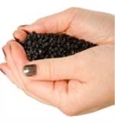

Figure 2‑3 Bottle and Containers (WERS Waste) Figure 2‑4 Pellets from Recycled Plastic
After the HDPE is separated from the batch plastic, it is shredded and fed through an extruder and where it is further refined by melting it down. It is then passed through a die where it is cooled by water and sliced up by blades to produce the pellets. Balers are also used to compress the waste plastic to reduce transport energy (Thomas, 2012).
Many initiatives can be taken to help in recycling plastics, especially HDPE. Some of these include reusing milk containers and buying plastic bottles in bulk. Some shops reward customers who with collection points if they use carrier bags, which help cut down the use of plastic bags. The resin identification code for HDPE is ‘2’, and this is placed on plastic bags to help separation during recycling (Thomas, 2012).
2.2. Recycling
The following is a brief description of WERS Waste, its founders, the company’s services and capabilities. Also outlined is a brief history and description of recycling in Ireland and future plans for it.
2.2.1. Recycling in Ireland
In March 2002, the Plastic Bag Levy was introduced in Ireland to encourage consumers to use reusable bags when shopping. It was the first legislation of its kind and was a huge success that paved the way for other countries to follow suit. Before the levy, there were approximately 1.2 billion plastic bags dispensed per year in Ireland free of charge. Before the levy, retailers placed no limit on the amount of plastic bags customers used while shopping and many of these bags were carelessly disposed of. The problem with the plastic bags is that they are non-biodegradable and they became a huge litter problem in urban and coastal areas because they are so visible (Anastasio and Nix, 2016).
The coalition government of 1997 decided to act on the increasing amount of pollution caused by the plastic. Studies were carried out and a proposal was put forward in 2000 to introduce a 15c charge on plastic bags. The proposal was introduced in March 2002 with retailers responsible for submitting levy returns. After the introduction of the levy, a study was carried out in 2005 and the findings showed that plastics accounted for 0.22% of litter compared to 5% prior to the levy (Anastasio and Nix, 2016).
The positives that came from the levy were that it reduced the amount of pollution both in urban areas (less litter on streets) and rurally as well (there was a problem with plastic bags caught in hedges and ditches). The reason for the drop in plastic bag usage was that people were less likely to spend money purchasing plastic bags each time they entered a shop and so there was an attitude change with consumers in Ireland (Anastasio and Nix, 2016).
In 2007, the levy was increased to 22c per bag and has created over €200 million in revenue which has been used in various environmental projects. As of 2015, plastic bags account for 0.13% of the litter in Ireland. Because of Irelands plastic bag levy, other countries introduced similar legislations such as Belgium with its eco-taxation on disposable plastic bags, disposable kitchen utensils, food wrap and aluminium foil. Romania also introduced its own eco-taxation on plastic bags (Anastasio and Nix, 2016).
2.2.2. History of WERS Waste
WERS Ltd. was established in 1989 in Tuam, Co. Galway. It was set up by the three Gleeson brother; Paul, Pat and Martin. WERS Ltd was one of the first companies to provide a wheelie bin service in Ireland. Today they provide the service to County Galway, south Mayo and south Roscommon (Waste Waste Tuam Wers Tuam County Galway Wers Recycling Tuam County Galway WERS Refuse Collection Tuam, no date).
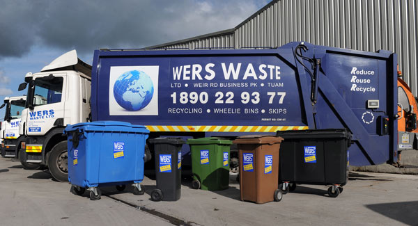
Figure 2‑5 WERS Lorry (WERS Waste Donegal)
The wheelie bin service comprises of three bins; the blue is for all clean, dry recyclables, the brown bin for organic compost waste and the black for all other waste. Waste bags are also available in local shops for those who do not possess a wheelie bin. The company’s main goal is to recycle as much waste as possible due to the decrease amount of space for landfill waste (Waste Waste Tuam Wers Tuam County Galway Wers Recycling Tuam County Galway WERS Refuse Collection Tuam, no date).
2.2.3. WERS Services
With over 6,000 customers, WERS Ltd market is divided into two sectors; Domestic and Commercial. The domestic sector refers to household collection of waste such as the wheelie bin service while the commercial sector is collection of waste from businesses via skip hiring, bins or compactors. Construction waste is also included in the commercial service. Another service, Bring/Clear-out service, is available for all waste except organic. This is where the public can deliver waste materials to the Tuam facility (Waste Services Tuam Waste Services Galway Waste Services County Galway WERS Waste Collection Services Tuam, no date).
2.2.4. HDPE and PP Compound
One of the main goals of WERS Ltd is to reduce the amount of waste that goes into landfill. One of the initiatives taken by WERS is the production of plastic pellets from HDPE (High Density Polyethylene) and PP (Polypropylene) plastic. HDPE is common in shampoo and detergent bottles, milk containers, compost bins, outdoor furniture and bins. Starting in 2009, WERS invested in a pelletizer machine to produce plastic pellets from used plastic. The plastic is separated from the batch plastic on a conveyor. It is then compressed using a baler, cleaned and shredded into pellets or flake. It is the company’s aim to provide these pellets to both the Irish and European markets which will help reduce the amount of plastic in landfill (HDPE PP Compound Waste Waste Tuam Wers Tuam County Galway Wers Recycling Tuam County Galway WERS Refuse Collection Tuam, no date).
2.3. Product – Crown Underwater Pelletizer
The machine used by WERS Ltd to produce plastic pellets is a Crown Underwater Pelletizer. The general operation is that the plastic is fed from the hopper into the twin extruder. The material is transferred along the barrel while being heated. The material becomes a molten polymer which is extruded through a die. Once through the die, the polymer is solidified by water and rotating blades cut the material up into pellets. The pellets are forced out the chamber by the water where they are dried. The pelletizer uses a closed loop system and so the water is reused (Underwater Pelletizers and Pelletizing – CROWN Machine uwp, Inc., no date).
The pelletizer has the capacity to produce between 1kg/hr and 30,000 kg/hr. This depends on the die and material being used. The pellets that can be produced can range from large pellets of between 1.2 mm and 10.0 mm to small-micro pellets of between 0.25 mm and 1.1 mm (Underwater Pelletizers and Pelletizing – CROWN Machine uwp, Inc., no date).
The following is a brief description of some of the main components of the Crown underwater pelletizer.
2.3.1. Twin Screw Extruder
The twin-extruder comes in sizes between 30 mm and 260 mm with various designs of screws and barrels. The polymer material is fed into the extruder throat via a hopper. Inside the extruder barrel, the polymer is melted, by heaters, into a molten state. The screw itself is self-cleaning due to co-rotating and intermeshing and can be used on all thermoplastics, non-thermoplastics and rubber materials (Twin Screw Extruders and Extrusion – CROWN Machine uwp, Inc., no date).
2.3.2. Die
This die in the pelletizer is known as a ‘Anti-Freeze Die’. It can be made of four different materials; Ceramic-Titanium, Pure Ceramic, Titanium-Carbide or Tungsten-Carbide. The reason for these so-called advanced materials is that the process of pelletizing requires operational temperature ranges without causing die-hole freeze off. These materials also allow hotter polymers to flow through the die while also dealing with cold water impact (Underwater Pelletizers and Pelletizing – Anti-FreezeTM Die – CROWN Machine uwp, Inc., no date).
2.3.3. Water Chamber
This is the chamber where the molten polymer comes into contact with the water and solidifies. It is known as an ‘Easy Flow Anti-Turbulent Water Chamber’. The purpose of the chamber is to eliminate random pellet impact as well as ‘fines’ and ‘angle hair’ on the pellets. The chamber reduces water turbulence and the demand for horsepower as well. Overall, it improves water chamber flow (Underwater Pelletizers and Pelletizing – Water Chamber – CROWN Machine uwp, Inc., no date).
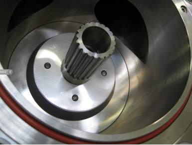
Figure 2‑6 Anti-Turbulent Water Chamber (Crown)
2.3.4. Blades
The blades in the pelletizer are ‘4-Edged Cutter Blades’. The surface of the blades is coated in plasma or polycrystalline diamond (PCD) which doubles the life of the blades and its efficiency (Underwater Pelletizers and Pelletizing – 4-Edge Cutter Blades – CROWN Machine uwp, Inc., no date).
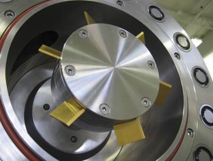
Figure 2‑7 Cutter Hub with six 4-edged blades (Crown)
2.3.5. Diverter Valve
The purpose of the ‘Polymer Hydraulic Diverter Valve’ is to prevent polymer leakage and seizing. This is achieved by the use of a high shear seal. The valve and piston is made from precision ground allot steel. The accumulator’s hydraulics allow instantaneous opening and closing of the valve to one-tenth (0.10) of a second. The diverter valve eliminates overflow in the water chamber and timing issues that cause die hole freeze-off (Underwater Pelletizers and Pelletizing – Polymer Hydraulic Diverter Valve – CROWN Machine uwp, Inc., no date).
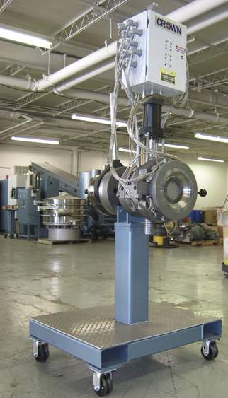
Figure 2‑8 Diverter Valve (Crown)
2.3.6. Water Tempering
Water tempering is achieved using a 3-phase water pump made with stainless steel housing. The heat exchanger allows a 15oC drop in process water temperature with an inlet range of 62oC and 87oC. The pump also has a 11-gauge stainless steel water reservoir with 40 mesh inlet screen strainer. The filter allows to the pump to remain clean without the need to shut it down during operation (Underwater Pelletizers and Pelletizing – Water Tempering – CROWN Machine uwp, Inc., no date).
2.3.7. Super Dryer
The ‘Super Belt Dryer’ dewaters the pellets, fluidizes and classifies them as well the drying them. It is capable of drying micro and mini pellets with the final product containing 0.05% moisture. The dryer is capable of drying 50 to 50,000 kg/hr of material (Underwater Pelletizers, Pelletizing, Micro Pellets – Super Dryer – CROWN Machine uwp, Inc., no date).
2.3.8. Water Bypass
The water bypass allows the operator of the pelletizer to service it and the die without the need of stopping water circulation or changing water temperature. The water bypass is integrated with the polymer hydraulic valve and automated control system (Underwater Pelletizers and Pelletizing – Water Bypass System – CROWN Machine uwp, Inc., no date).
2.3.9. Magnetic Clamp
This is a new feature to the Crown pelletizer. Using 1 tonne of clamp force to close and seal the water chamber (Underwater Pelletizers and Pelletizing – Magnetic Clamp – CROWN Machine uwp, Inc., no date).
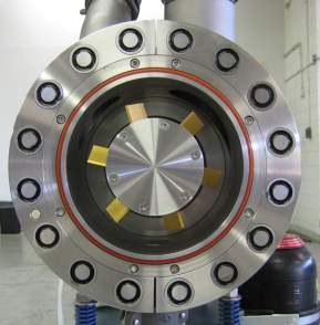
Figure 2‑9 Magnetic Clamp (Crown)
2.3.10. Touch Screen
The pelletizer uses a 15” touch screen for operating. Some of the features include a component fault alarm, program storage, trending charts for real time die temperature and pressure. Also, the pelletizer can be controlled via internet connection (Underwater Pelletizers and Pelletizing – Touch Screen Control – CROWN Machine uwp, Inc., no date).
2.4. Design Constraints
The following is a list of the constraints that need to be taken into account when redesigning the die ring. These constraints will in some way hinder the design process but need to be highlighted early, before designing so as no mistakes will be made and that the design is efficient.
2.4.1. Die Hole Freeze-off
Die hole freeze-off is when the die holes become plugged with polymer. If the holes become plugged, the die becomes less efficient and the pellets that are produced can be larger or irregularly shaped. Also, because of the plugged holes, the efficiency of other holes around the plugged hole(s) can be affected as well. If it continues, the production decreases and the line has to be shut down in order to clean the die (Darley, 2006).
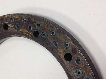
Figure 2‑10 Example of Die Hole Freeze-off
The following is a list of potential causes of die hole freeze-off.
2.4.1.1.Improper start-up
During the start-up sequence, the resin, cooling water and the cutter must be started in the proper sequence. If the resin flows first through the die before the cooling water, and the cutter engages, smearing will occur and the resin will block the die holes on the outside in the water box. Also, if the water reaches the die face before the flow of polymer, the die will cool and cause die hole freeze-off (Darley, 2006).
2.4.1.2.Die design issues
One of the most common problems with die designs is the lack of insulation. Electric cartridges are used but are placed at the outer edge and so only the die holes nearest the edge can benefit from them. Oil heating systems have been used but are expensive and are only used for high-output lines. If the oil valve plugs or fails, the holes closest to the blockage will cool and could possibly freeze. Most dies eradicate these problems by insulating the die using special plates that are attached to the middle of the die face but these can become loose. If they do loosen, water can get behind the plate and cool the die, causing freeze-off. Another method use to prevent freeze-off is a vacuum hollow in the die which is a good insulator and can’t be compromised (Darley, 2006).
2.4.1.3.Process Fluctuations
Interruptions in process flow and output of material can lead to die hole freeze-off. The freeze-off can be quite random and can be caused by trapped air in the flow of material (Darley, 2006).
2.4.2. Possible Die Design Solutions
Outlined above are common problems with underwater pelletizing. The most common problems with underwater pelletizing, according to Gala Industries, are die selection, sizing and output fluctuations which can lead to pellet inconsistency. The following is a list of causes of pellet inconsistency and possible solutions.
2.4.2.1.Improper Die Sizing
This can lead to poor polymer flow across the die and solidification of the polymer in the die. The correct polymer velocity and die temperature must be maintained in order to prevent this. The correct velocity through the die is 2.5 to 3 ft./sec which is equal to 0.762 to 0.914 m/s. A die hole of 3.2 mm (0.125 in) requires approximately 50 to 60 lbs/hr or 22.67 to 27.21 kg/hr (Tate, 2014).
The specific gravity of the material needs to be taken into account when sizing the die. HDPE has a specific density of approximately 0.95. Therefore, 47.5 to 57 lb/hr or 21.54 to 25.85 kg/hr of HDPE should pass through the die. The formula for calculating the correct amount of holes is as follows:
X = R x 7.6/ (W x S x N)
- X = Number of holes in the die
- R = Rate in lb/hr
- W = Weight in grams per pellet
- S = Speed of the pelletizer in RPM
- Number of blades in the cutter hub
2.4.2.2.Improper Die Temperature
The die temperature needs to be 25 oF greater than the polymer melt temperature although this can vary from material to material. Insulation of the die is very important and all parts of the die except for the cutting face should be isolated from the process water. High temperature, room-temperature-vulcanizing (RTV) silicone is used to seal the insulation. Signs that indicate loss of insulation are if the die temperature drops from the start set point and the control system calls for heat, the die struggles or never fully returns to the original die set point. A test to check this problem would be to check the amp draw for each heat zone and then check the actual reading. The less the reading, then one or more of the heaters is faulty (Tate, 2014).
2.4.2.3.Die Hole Blockage
This is when the die holes become physically blocked by polymer because of contaminants in the polymer. A solution to this is the implementation of a screen changer or filtration system. On a smaller system, the die is simply removed and cleaned (Tate, 2014).
2.4.2.4.Fines and Tails on the Pellets
Die and blade wear can lead to fines and tails on the pellets. If grooves occur on the die plate, a brand new and razor sharp blade will pull material through the groove and cut, causing a tail. The tail breaks off in the centrifugal dryer, which creates a fine. Fines create problems in material-handling systems and increase moisture content in the pellet. Melt fracture also leads to increase in moisture content. This is where a pellet is porous due fillers, irregular pellet shape and operating parameters.
Melt fracture can be reduced by cutting the pellet thinner. Reducing the velocity can also reduce melt fracture. Polishing and honing the die also helps. Concurrent air flow through the dryer is very important in reducing the air flow (Tate, 2014).
2.4.3. Pressure
The pressure at the head in the Crown underwater pelletizer was found to be approximately 2250 psi and rising 2750 psi prior to a filter change. It has a minimum operating pressure of 500 psi and is limited to 3500 psi. The pelletizer will ‘trip’ at 3500 psi, therefore this needs to be taken into account when designing the die and calculating the amount of material to be processed.
2.4.4. Die Hole Diameter
The diameter of the die holes is 3.2 mm and this cannot be altered because the clients of WERS Ltd require 3.2 mm plastic pellets.
2.4.5. Extruder Capacity
The extruder capacity of the Crown underwater pelletizer is unknown. Tests will need to be carried out to determine the capacity of the extruder. Increasing the output of the pelletizer will depend on the extruder capabilities and this will affect the design of the die.
3. Chapter Three – Materials and Methods
The following chapter outlines some of the methods used in the project so. Also outlined are some reasons for investigating these issues in relation to the underwater pelletizer. Not all areas of this chapter have been carried out so far, and this is highlighted in the work-done-to-date in chapter four.
3.1. Die Ring
The die ring is an essential part of the die fixture in the underwater pelletizer. It is a ring that is placed in the water chamber between the die head and the cutter blades. The die ring can be made from any one of the following materials;
- Ceramic-Titanium.
- Pure Ceramic.
- Titanium-Carbide.
- Tungsten Carbide.
The die ring that is currently in the underwater pelletizer in WERS Ltd is made from 01 Tool Steel. This is an oil hardened tool steel which is durable, has excellent wear resistance and has a good cutting edge. Some of the applications of 01 Tool Steel are medium run dies, press tools, lathe centres and chuck jaws to name a few (O1 Tool Steel – West Yorkshire Steel – Fully ISO 9001 Approved, no date).
The current die ring has 54 holes for material to pass through. This is the same on the die head. The holes on the die ring are arranged in two concentric circles. The outer circle contains 30 holes while the inner circle contains 24 holes. These holes have a diameter of 3.7 mm.
Throughout the die, there are 12 holes for the counter-sink screws. These holes have a counter bore diameter of 8.6 mm and to a depth of 8.5 mm. These holes have a diameter of 5 mm for a M5 screw.
3.1.1. Number of Die Holes
The current die ring has 54 holes. The amount of material being passed through the die is approximately 350 kg/hr. In order to increase the material output, WERS Ltd want the student to design a die with more holes so that a larger amount of material can pass through the die. A rough estimate of the amount of material that WERS Ltd would like to be processed is double the current amount. Therefore, they want to achieve at least 700 kg/hr of HDPE through the die.
The student investigated the amount of material that passes through each die hole, its velocity, mass flow rate, volumetric flow rate and relayed this information to WERS Ltd to ensure the results matched physical evidence and desired specifications.
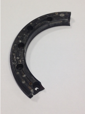
Figure 3‑1 Current Die Ring (Shattered)
3.1.2. Removing the Countersink Bolts
Another design problem that the student had to deal with is the removal of the M5 countersink screws. Presently, the cutter blades wear into the die ring over time. This also wears into the screw heads and can damage them. If the damage is severe enough, the screws have to be drilled and tapped out. This can be a nuisance when replacing the die ring.
Another reason for justifying the removal of the countersink screws is to decrease the amount of time that is spent changing/replacing the die ring. WERS Ltd wants to implement a design that is efficient and practical which will decrease down time and therefore less down-time leads to increased productivity.
3.1.3. Die Ring Material
The current die ring is made from 01 Tool Steel. This is not one of the four materials recommended by Crown to use on the die. The four materials; Ceramic-Titanium, Pure Ceramic, Titanium-Carbide, Tungsten-Carbide each possess characteristics that allow the die ring be subject to a wide range in temperature changes that allow hot polymers to pass through the die and cold water to come into contact with the die cutting surface without causing die hole freeze off.
The current die was not manufactured by Crown but was installed by WERS Ltd. The student will need to investigate the relationship between the die ring material and the flow of material through the die and how does the material affect the productivity of the pelletizer.
4. Chapter Four – Work done to-date
The following is a detailed description of the work carried out on this project so far. Majority of work completed is calculations and is theoretically based. Fluid mechanics was a huge assistance for this part of the project and much of the formulas, equations and techniques used by the student were gained from the fluid mechanics module they studied.
4.1. Length of Cuts
This was first part of analysis the student undertook. It involved investigating the flow of material through the die, and more specifically, the amount of material through each die hole. The student collected some data from WERS Ltd on the pelletizer. The student also acquired drawings of the die ring. The following is a list of some of the data and specifications on the pelletizer.
| Diameter of die hole | d | 3.2 | mm |
| Radius of die hole | r | 1.6 | mm |
| No. of die holes | x | 54 | holes |
| Pressure in Extruder | P | 2250 | psi |
| Density of material (HDPE) | ρ | 950 | kg/m^3 |
| Mass flow rate of material | m’ | 350 | kg/hr |
| Speed of pelletizer | S | 950 | rpm |
| No. of blades in cutter hub | N | 6 | blades |
Table 4‑1 Figures & Data from Pelletizer
 The first calculation was the area of each die hole. The diameter of holes in the die are already given as 3.2 mm. Using the area of a circle equation, the area was calculated using the radius of the holes.
 The speed of pelletizer is given as 950 revolutions per minute (RPM). In order to find the length of each cut, this was converted to revolutions per second (RPS). Therefore, the speed of the pelletizer is;
HDPE PP Compound Waste Waste Tuam Wers Tuam County Galway Wers Recycling Tuam County Galway WERS Refuse Collection Tuam (no date). Available at: http://www.werswaste.ie/hdpe-pp-compound.htm (Accessed: 7 January 2018).
O1 Tool Steel – West Yorkshire Steel – Fully ISO 9001 Approved (no date). Available at: https://www.westyorkssteel.com/tool-steel/o1/ (Accessed: 8 January 2018).
Tate, M. (2014) Solving Common Problems in Underwater Pelletizing : Plastics Technology. Available at: https://www.ptonline.com/articles/solving-common-problems-in-underwater-pelletizing (Accessed: 11 January 2018).
Temin, P. (1995) Two views of the British industrial revolution : Temin, Peter : Free Download & Streaming : Internet Archive. Cambridge, Massachussetts: Dep. of Economics, MIT. Available at: https://archive.org/details/twoviewsofbritis00temi (Accessed: 10 January 2018).
Thomas, G. P. (2012) ‘Recycling of High Density Polyethylene ( HDPE or PEHD )’, (July, 25), pp. 1–4. Available at: http://www.wrap.org.uk/sites/files/wrap/WRAP_Large_Scale_HDPE_Recycling_Trial_Re port.4328448f.3769.pdf.
Twin Screw Extruders and Extrusion – CROWN Machine uwp, Inc. (no date). Available at: http://www.cdli.com/twin_screw.html (Accessed: 7 January 2018).
Underwater Pelletizers, Pelletizing, Micro Pellets – Super Dryer – CROWN Machine uwp, Inc. (no date). Available at: http://www.cdli.com/super_dryer.html (Accessed: 7 January 2018).
Underwater Pelletizers and Pelletizing – 4-Edge Cutter Blades – CROWN Machine uwp, Inc. (no date). Available at: http://www.cdli.com/blades.html (Accessed: 7 January 2018).
Underwater Pelletizers and Pelletizing – Anti-FreezeTM Die – CROWN Machine uwp, Inc. (no date). Available at: http://www.cdli.com/die.html (Accessed: 7 January 2018).
Underwater Pelletizers and Pelletizing – CROWN Machine uwp, Inc. (no date). Available at: http://www.cdli.com/underwater.html (Accessed: 7 January 2018).
Underwater Pelletizers and Pelletizing – Magnetic Clamp – CROWN Machine uwp, Inc. (no date). Available at: http://www.cdli.com/magnetic_clamp.html (Accessed: 7 January 2018).
Underwater Pelletizers and Pelletizing – Polymer Hydraulic Diverter Valve – CROWN Machine uwp, Inc. (no date). Available at: http://www.cdli.com/diverter_valve.html (Accessed: 7 January 2018).
Underwater Pelletizers and Pelletizing – Touch Screen Control – CROWN Machine uwp, Inc. (no date). Available at: http://www.cdli.com/touch_screen.html (Accessed: 7 January 2018).
Underwater Pelletizers and Pelletizing – Water Bypass System – CROWN Machine uwp, Inc. (no date). Available at: http://www.cdli.com/water_bypass.html (Accessed: 7 January 2018).
Underwater Pelletizers and Pelletizing – Water Chamber – CROWN Machine uwp, Inc. (no date). Available at: http://www.cdli.com/water_chamber.html (Accessed: 7 January 2018).
Underwater Pelletizers and Pelletizing – Water Tempering – CROWN Machine uwp, Inc. (no date). Available at: http://www.cdli.com/water_tempering.html (Accessed: 7 January 2018).
Waste Services Tuam Waste Services Galway Waste Services County Galway WERS Waste Collection Services Tuam (no date). Available at: http://www.werswaste.ie/waste-services.htm (Accessed: 7 January 2018).
Waste Waste Tuam Wers Tuam County Galway Wers Recycling Tuam County Galway WERS Refuse Collection Tuam (no date). Available at: http://www.werswaste.ie/about.htm (Accessed: 7 January 2018).
Cite This Work
To export a reference to this article please select a referencing stye below:
Related Services
View all


Related Content
All TagsContent relating to: "Engineering"
Engineering is the application of scientific principles and mathematics to designing and building of structures, such as bridges or buildings, roads, machines etc. and includes a range of specialised fields.
Related Articles

DMCA / Removal Request
If you are the original writer of this dissertation and no longer wish to have your work published on the UKDiss.com website then please: