Groundwater Control and Waterproof Systems for Construction of Deep Basements
Info: 11966 words (48 pages) Dissertation
Published: 25th Nov 2021
Tagged: ConstructionTechnology
Contents
Click to expand Contents
Chapter 1: Introduction
1.Introduction
2. Background
3. Scope of research
4. Thesis Aims and Objectives
5. Personal Interviews
6. The case study
7. Summary of Chapters
7.1 Chapter One Introduction
7.3 Chapter Two Research Methodology
7.2 Chapter Three Literature Review
7.4 Chapter Four the Case Study
7.5 Chapter Five: Findings and Analysis
7.6 Chapter Six Conclusion
Chapter 2. Methodology
2. Introduction
2.1 Research Methodology
2.2 Qualitative Data Research
2.3 Quantitative Research
2.4 Personal Interviews
2.5 Structured Interview
2.6 Process Recall
2.7 The Case Study
2.8 Documented Research
2.9 Primary research
2.10 Secondary Research
2.11 Journals
2.12 Government Publications
2.13 Database and Internet
2.14 Newspaper Articles
Chapter 3. Literature Review
3. Introduction
3.1 Ground Investigation
3.2 Site Reconnaissance
3.3 Desktop Study
3.4 Water Table
3.5 Geotechnical Investigation
3.6 SPT Test
3.7 Trial Pit excavation
3.8 Ground Water Control
3.9 Objectives of Groundwater Control
3.10 Sump pumping
3.11 Wellpoints
3.12 Retaining Wall Systems
3.12.1 Sheet Piling
3.12.2 Contiguous Piling
3.12.3 Secant Piling
3.12.4 King Post Walls
3.12.5 Diaphragm Walls
3.13 Waterproofing Basements
3.13.1 Site preparation and the control of moisture
3.14.1 Type A: Tanked Protection Barrier System
3.14.2 Type B: Structural Integral System
3.14.3 Type C: Drained System
4. Case Study
Introduction
4.1 Background
4.2 Geotechnical Survey and Desktop Survey Undertaken
4.3 Water Table and Groundwater Control
4.4 Waterproofing Methods
Chapter 5. Findings and Analysis
5. Introduction
5.1 Findings Desktop Survey
5.2 Findings Groundwater Control
5.3 Findings Retaining Wall System
5.4 Findings Waterproofing
5.5 Analysis
5.6 Desktop Survey Analysis
5.7 Groundwater Control Analysis
5.8 Retaining Wall System Analysis
5.9 Waterproofing Analysis
Chapter 6. Conclusion and Recommendation
Introduction
6.1 Conclusion
References
Figure 1 Standard shell and argur rig
Figure 2 N Value Table
Figure 3 Example of an Excavated Trial Pit
Figure 4 Hydrostatic Pore Water Pressure Distribution
Figure 5 Wellpoints being installed via Cable Percussion Boring System
Figure 6 BS 8102 Guidance Table
Figure 7 Type A Tanking System
Figure 8 Type B Structural Integral Protection
Figure 9 Type C Drained System
Figure 10 Case Study Specifics
Figure 11 Architects model of the completed Building
Figure 12 Buildings that were purchased by the Royal College of Surgeons Ireland
Figure 13 Basement at sixteen metres deep
Figure 14 Thesis Findings Triangulation
Chapter 1: Introduction
1. Introduction
The Oxford English dictionary (Oxford English Dictionary, 2017) defines a basement as “The floor of a building which is partly or entirely below ground level”.
The current period of continued economic growth within the construction sector of Ireland has led to an increase in the use of underground space, with some developments now including several underground levels. However, it has also been noted that during the development of marginal sites, for example in areas of Dublin City Centre, basements have not been utilised to their full potential.
Since the price of property in Dublin City Centre has risen vastly, Buildcost Chartered Quantity Surveyors cost guide estimated in 2012 it cost €1100 to €1500 to construct one square metre of office space, the variance cost range of €600 due to specifications such as Mechanical and Electrical (Buildcost, 2012). Where as in 2017 it currently costs €1,750 to €2,250 to build one square metre as per above the variance is specification (Buildcost, 2016) construction in the past number of years and continues to do so, it has become ever more popular for the construction of large basements, these basements can facilitate parking, storage or be habitable by people.
A major factor influencing the necessity to excavate deeper underground and use basements is Dublin City Council having a robust planning system in place that limits the height of newly constructed buildings within Dublin City Centre. This is explained in greater detail in the case study chapter.
2. Background
Over the past two years the author has worked for the Royal College of Surgeons Ireland on a full-time basis during the Summer months and a part-time basis during the academic calendar. Throughout this time frame the New Academic Educational Building was constructed, this gave rise in interest of deep basement construction having held numerous conversations with the project manager, design engineer and site foreman. After carrying out research it was discovered that there are three theses’ written on basement excavation, all from a financial perspective, but none from a construction project management perspective.
3. Scope of research
This thesis focuses primarily on the construction of deep basements in Dublin City Centre specifically, examining and evaluating groundwater control techniques, waterproofing systems, the value of site investigations and geotechnical surveys. The thesis also uses a case study that the author became familiar with over the past two years. The research is limited to brown field sites in Dublin City Centre, the findings may not be applicable to greenfield basement construction projects.
4. Thesis Aims and Objectives
The overall goal of this thesis is to consider basements in urbans developments as more than just a facility for car parks, that with the correct waterproofing the basement can be utilised for archive storage of sensitive materials or even human habitation. It will also postulate that with correct planning systems and investigations in place project delays will be avoided. Other phenomenon that will be appraised are the benefits of:
- Site Investigations
- Desktop surveys
- Understanding the water table to control groundwater
- Waterproofing Basements
5. Personal Interviews
Interviews are principally useful for attaining the story behind an interviewee’s experiences. The interviewer can attain in-depth information around the subject matter. Interviews can be useful as follow-up to certain respondents to questionnaires, to further investigate their responses and experiences. Throughout the past ten years, there has been a noted rise in the use of qualitative research in academic studies and research techniques. (Boodhoo, 2009)
The method of interview questions that were undertaken for this thesis were both structured and recall process. There were eight questions in all asked during the interview, two questions on four problematic areas. The first question was structured, whereas the second question was recall process. This laid the foundation of the interview, but also allowed for free-flowing answers, which granted the author a deeper understanding of the questions being answered.
6. The case study
The case study, or observation study, comprises of three differing methodologies. These methods were: tracing or studying documents, studying behaviour and/or personal observation. The information provided the author with real experiences of the case study undertaken, on how problems were addressed or in some cases circumvented. The case study chosen was an almost completed nine storey building, with a four storey beneath ground basement located on York Street, Dublin, this project was chosen as it was, at the time, the deepest basement constructed in Dublin. It fast became the logical option to use this as a thesis case study as it also benefitted from access to various senior personnel involved within the project.
7. Summary of Chapters
The information provided below, affords the reader with a brief summary of content of each chapter throughout the thesis.
7.1 Chapter One: Introduction
In this chapter, the author introduces the thesis subject matter. It provides a transitory background to the influence of the thesis topic, as well as the requirement for the case study to be constructed sixteen meters belowground. The objective and aims are clearly defined, as well as the methods of primary research that were undertaken.
7.3 Chapter Two: Research Methodology
This chapter draws attention to the methods of research that was undertaken by the author, it also gives a clear definition to what primary and secondary research are. It distinguishes the differences between qualitative and quantitative research methods. It also provides clear and concise information on how the primary research interviews were conducted. Also highlighted was the case study, and how it aided the necessity for research.
7.2 Chapter Three: Literature Review
This chapter encompasses a comprehensive literature review, methodically researched by the author on any material that was felt pertinent to aid the preparation of this thesis. The secondary literature examination was sourced primarily from the Info4education database, as well as academic journals, and books written on the subject. The researcher will summarise the material that provides the reader with data on the following:
- Importance of site investigations and how vital data can be attained from desktop surveys
- Geotechnical investigations
- Understanding the Water table to control groundwater
- Waterproofing Basements
7.4 Chapter Four: the Case Study
The aim of this chapter is to provide an elucidation to why the case study in question was prudently selected, it gives the reader a clear background on the requirements for a deep basement to be constructed as well as brief historical uses of the buildings. The buildings were subsequently demolished to facilitate the construction of the New Advanced Education Building. It also clarifies problems encountered during phases of the construction element to the project.
7.5 Chapter Five: Findings and Analysis
In this chapter, the results of the data analysis are presented. The data was collected and then processed in response to the problems posed in chapter one of this dissertation. Fundamental goals drove the collection of the data and the subsequent data analysis. Those goals were to advance on a base of knowledge about the problems encountered on basement construction and how these problems can be circumvented or eradicated due to diligent planning. These objectives were accomplished, and the subsequent findings are presented within this chapter.
7.6 Chapter Six: Conclusion
Within this chapter, the key conclusions are highlighted followed by subsequent recommendations
Chapter 2. Methodology
2.1 Research Methodology
An extensive literature review was carried out from all possible resources available to the author on the subject matter and its associated problems. The most relevant and practical collection of data methods incorporated were recorded via face to face interviews, exploration of available documents and the utilisation of a case study located on York Street in Dublin 2. Each of the methods outlined provide independent validated data.
2.2 Qualitative Data Research
Qualitative research was sourced information not in numerical form. The example being interviews conducted which demonstrated open-ended questions with process recall questions also asked during an interview. Qualitative data is typically expressive data and as such, is more difficult to analyse than quantitative data. Qualitative research was valuable for studies at the individual level and to ascertain, in depth, the ways in which interviewees felt were the most practical methods utilised during previous projects. The qualitative research also allowed the author to gain an insight into how other construction techniques could complement and enhance modern construction methods.
2.3 Quantitative Research
Quantitative research collects and compiles data in numerical form which is put into groups, in order or measured in varying units of measurement. The nature of the information obtained is then utilised to create graphs and tables of data. In Quantitative Research, researchers have a tendency to stay objectively separated from the topic matter. Since quantitative research is objective in approach, in the logic that it only pursues precise measurements and analysis of targeted notions to answer and quantify the response(s). The quantitative research technique is to generally issue a questionnaire via email or post offering multiple choice answers, there are generally four plus answers to each question. This allows the researcher to annotate the results in varying graphs.
2.4 Personal Interviews
According to (M. Easwaramoorthy, 2006) “An interview is a conversation for gathering information. A research interview involves an interviewer, who coordinates the process of the conversation and asks questions, and an interviewee, who responds to those questions. Interviews can be conducted face-to-face or over the telephone.” The interviews that took place were a combination of structured and process recall questions. The participants of the interview procedure all had vast experience within the construction of deep basements as project managers or were design engineers who also managed the projects for their respective companies.
2.5 Structured Interview
During the structured interview, the author asked a set of four standard questions about the thesis topic in a specific order. The respondents answered by drawing on their experiences and expertise on basement excavation. The author provided clarification on some questions where they were misunderstood or the interviewee required further information on what was being asked(M. Easwaramoorthy, 2006)
2.6 Process Recall
The process recall interview allowed the author to obtain first-hand insights into how seasoned project managers and engineers went about the excavation of a deep basement on brown field sites. This was undertaken via asking the interviewee a set of four recall process questions regarding how pervious projects took place and the process that were implemented and accomplished.
2.7 The Case Study
The case study that was utilised is referred to as the NAEB located on 26 York Street, Saint Stephen’s Green, Dublin 2. The Royal College of Surgeons Ireland own this building. The building is a ten-storey structure with a basement of four-storeys in total depth. This case study provided the researcher with real life experience of how such a large basement was excavated and also aided the author to research the problematic issues that arise during the construction phase.
2.8 Documented Research
Primary and secondary research literature were undertaken by the author during the research element of this thesis, to investigate and evaluate the associated issues with construction on brown field sites in Dublin City Centre and how these issues were either circumvented or overcome.
2.9 Primary research
(Kowalczyk, 2015) Defines primary research as “Factual, first-hand accounts of the study written by a person who was part of the study. The methods vary on how researchers run an experiment or study, but it typically follows the scientific method. One way you can think of primary research is that it is typically original research.” This research was carried out via structured and process recall interviews as described previously.
2.10 Secondary Research
Secondary data analysis and review involved gathering and analysing an immense selection of information that was studied via reading journals, online articles, accessing Info4education database and reading government issued Technical Guidance Documents, which were also accessed online.
2.11 Journals
Academic journals were accessed to aid the authors secondary research techniques. Journals are monthly published articles that enable the presentation of research outcomes and findings by members of the academic community. The frequency of the publicised journals vary but tend to be published monthly, quarterly, annually, or biannually. The information found within these journals was of great benefit being as they were current and offered specialised information which helped during the writing of this thesis.
2.12 Government Publications
The Government Technical Guidance Documents that were of great benefit in terms of research carried out was “Drainage and Waste Water Disposal” commonly referred to as Part H of the Building Regulations 2010 and Part C “site preparation and Resistance to Moisture” commonly referred to as Part C of the Building Regulations 2010. These publications were compiled and issued by the department of Environment, Heritage and Local Government. These documents were an abundant source of guidance and understanding on the subject matter.
2.13 Database and Internet
A database is a collection of information that is organised so that it can be easily accessed. The database primarily utilised was Info4education. This database provided information for construction, health and safety, engineering process and the electronic industries. The internet is a global system of computer networks that connect computers worldwide. The Internet carries an extensive range of information and resources that aids research at every level.
2.14 Newspaper Articles
Various newspaper articles were accessed to assist with research. The most noted resultant being the BuildCost annually released building cost guide. Additional articles were read, but many did not influence research problems or outcomes.
Chapter 3. Literature Review
3. Introduction
This chapter includes a comprehensive literature review, methodically researched by the author on any material that was felt pertinent to aid the preparation of this thesis.
3.1 Ground Investigation
As Per Part C of the Building Regulations September 2004 (Site Preparation and Resistance to Moisture) Technical Guidance Document “In all cases, appropriate site investigations should be undertaken to check for the presence of contaminants. Contamination may arise from sources outside of the site e.g. landfill”(Government TGD, 2004).
3.2 Site Reconnaissance
Site reconnaissance is simply performed by walking the proposed site. This element of research helps to establish site access, overhead services and may highlight abnormalities that are not identified in the desktop study mentioned below. Ad hoc samples of vegetation will also be taken during the course of inspection. This process helps to identify the vegetation that grows on the proposed site and also gives vital information about the water table (British Standards, 2013).
3.3 Desktop Study
The desk study is a non-obtrusive procedure that comprises of putting together a picture of the proposed construction site, environmental geographical location and setting, which includes the geology, hydrogeology, hydrology, previous site history, mining/quarrying, landfill and waste, and any regulatory concerns from statutory bodies such as the Local Authority and the Environment Agency. This assists to identify any probable important features that may demand further examination such as potential contamination sources for ground conditions below a proposed structure. This survey also assists in identifying underground services such as: foul/surface water drainage systems, gas pipes, telecommunication cables and electrical cables. These services may very well be still live or inactive. A practical method of identifying the aforementioned services is to simply contact the service provider and request an underground network map (Geocon, 2017).
To aid the documentation of historical practice of the land, investigation undertaken should be companionable with the objectives of the examination. The amount of exploration into the history of the site will rely upon numerous factors including the complication of past potentially contaminative usage on and adjacent land or property to the site, the susceptibility of the site geology and local water conditions. This information will be gathered by examining ordnance surveying maps, aerial photographs and other published maps, for example: insurance, tithe, enclosure or parish maps.
Documental records will be gathered via contacting the current land owners to ascertain if they have any previous usage records, such as any significant usage for example industrial/manufacturing plants which may have produced biological hazards the example being asbestos, and contacting the planning department of the county council (Spillane, 2016)
3.4 Water Table
High water tables are the greatest hazard of failure of the water-tightness of a basement. If there is a long-lasting high water table, it is essential to identify it. A watercourse or water table that rises and falls along with climatic changes must also be identified. How regularly and for how long the water table remains high are also significant. If the water table increases briefly – say, later after heavy rain – and then directly falls again, the danger of water ingress via external waterproofing and then through the structure is less than if the water table stays elevated for a much longer period. The probable existence of water and the location of the water table must also be identified for construction reasons.
Water table classifications:
“High: where the water table or perched water table is assessed to be permanently above the underside of the base slab.
Low: where the water table or perched water table is assessed to be permanently below the underside of the base slab. This only applies to free-draining strata.
Variable: where the water table fluctuates.”
The topography of the land, the course/direction and movement of any groundwater ought to be identified, as they will have a bearing on any applications to supply drainage to decrease localised groundwater pressures. If there is the attendance of any drains and or land drains, their locations ought to be discovered and recorded. Any new construction proposals should not disturb drains that are still in operation, except if measures are taken to divert them or to capture the water via a new drainage system(British Cement Association, 1994)
3.5 Geotechnical Investigation
Below ground soil samples are gathered via an intrusive but non-disruptive method, commonly referred to as drilling or boring. This is a drop tool type drilling method which uses steel casing tubes to prevent collapse of the borehole during drilling. The rig comprises a large tripod and winch which are used to lift and drop heavy cutting tools down onto the base of the borehole. The type of tool used depends on the type of soil present. Clay cutters are used in heavy clays, bailers are used with water to remove gravels and chisels can be used to smash up hard strata at depth. Heavy hammer weights can also be added onto the tops of these cutting tools to increase the momentum of the dropping tool.
The clay-cutter is weighted with a steel sinker bar which weighs 60kg, this assembly can weight up to 150kg in completion. The cutting assembly is dropped three meters above the bottom of the hole. It imbeds itself in to the soil, and the rig operator then utilises the rig to slowly remove the soil from the ground and lift it to the surface. The soil sample is now removed, recorded, and preserved for laboratory testing. The clay-cutter is not used in soft soils, it is generally used after the first 300mm-500mm of soft soil is removed. The amount of disturbed soil below the base of the borehole can be expected to be small enough not to influence the SPT test (Clayton, 1995).
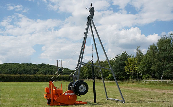 Figure 1 Standard shell and argur rig (Dando, 2016)
3.6 SPT Test
Standard Penetration Test, SPT, comprises of driving a standard dense-walled sample cylinder into the ground at the base of a borehole by blows from a slide hammer with standard weight and falling distance. The sample tube is driven 150 mm into the ground and then the number of blows needed for the tube to penetrate each 150 mm up to a depth of 450 mm is recorded. The quantity of the number of blows essential for the second and third 150 mm of penetration is reported as the SPT blowcount value, commonly termed” standard penetration “or “N Value”.
The N-value provides a signal of the relative density of the subsurface soil, and it is used in the geotechnical relationship to evaluate the estimated shear strength properties of the soils (Geotechdata, 2017).
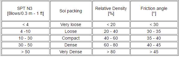 Figure 2 N Value Table (Geotechdata, 2017)
3.7 Trial Pit excavation
Trial pits produce such data as soil classification, how well the edges and sides of the excavation stand up, the location of the water-table, whether ingress of groundwater will be an issue, the ease of level, the invert of the dig, possible decline of the soil on contact with the atmosphere, the depth and presence of fills, and the difficultly and ease of the excavation. Boreholes can identify and highlight sandstone, for example, which will tend to price with high excavation charges yet the trial pit excavator may well be able to excavate the rock easily.
Trial pits will be excavated down to at least the pre-stated excavation level by an Engineer, and on difficult sites the information collected will be used as a useful supplementary aid to foundation construction and design. They can also act to support a visual check, on the likely dependability of test information gathered. From a health and safety aspect the sides of the pit are prone to failure, and any person who requires to gain access, then propping will be provided to protect the investigator, and/or the sides will be supported or stepped by the excavator.
Where the site is open to access by people, the pits will be backfilled with any soil removed or securely isolated at the end of each day. When it is necessary to check, over a period of time, degradation or seepage, the pit will be covered over with planks of timber and covered with tarpaulins, the pit(s) will then be secured from access via the usage of a Harris fencing system.
The ground level, position and invert levels of the pits will to be documented in tandem, alongside the findings of soil classification, properties and levels of the strata. Colour photographs of the sides of the pits are of great use, and the photographs have ever amplified value if a ranging rod is contained within to confirm the scale. Where the presence of underground services is suspected, trial pits can be used to locate them, preferably by careful hand-digging or via the use of a CAT scanner
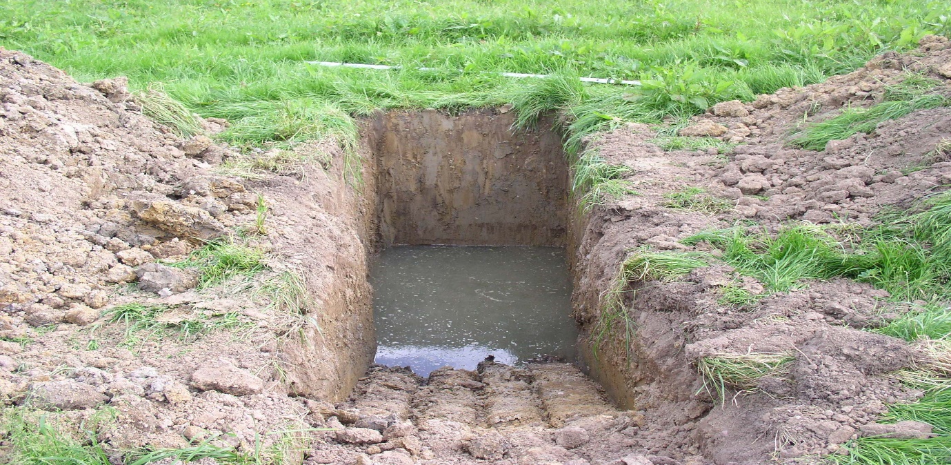
Figure 3 Example of an Excavated Trial Pit (Geotechdata, 2017)
3.8 Ground Water Control
Each time an excavation is completed underneath the natural water table, there is a danger that it may become unstable or overflow, except if measures are taken to govern the groundwater in the adjacent soil. Groundwater may be controlled by creating a physical barrier to reject groundwater from the excavation, or alternatively by pumping groundwater from specifically installed wells, to artificially reduce the water table in the vicinity of the excavation, or by an amalgamation of the two systems. Quite frequently, the use of a pumped well system, either a standalone system or in tandem with a physical barrier, will be the most inexpensive and suitable approach. The most appropriate form of pumped well system to utilise centres on primarily, the nature of the ground and the depth of the excavation.
Natural pore water pressures in the ground, the regular pore water pressures in the ground present on a construction site are dependent on the ground environments and the natural groundwater flow rule. The water table is described as the level at which the pore water pressure (measured relative to atmospheric pressure) is zero. If the groundwater is in a state of rest, the pore water pressures will be hydrostatic.
Non-hydrostatic conditions are typically connected with substantial vertical groundwater flow. One instance of this is when the pore water pressure in a restricted aquifer is high enough to cause water to flow extremely slowly upwards through the overlying aquiclude.
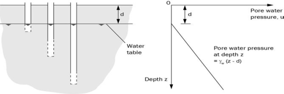
Figure 4 Hydrostatic Pore Water Pressure Distribution (W Preene, 2016)
3.9 Objectives of Groundwater Control
The obvious, but not essentially the most significant objective of groundwater control is to avert an excavation beneath the natural water table from flooding. Groundwater control will likewise have a significant role to play in the controlling of pore water pressures in and round an excavation, in order to guarantee stability of the excavated base and subsequent side slopes.
Groundwater control is attained via physical elimination e.g. a cut-off wall, via pumping from sumps or wellpoints to capture the groundwater before it reaches the excavation, or by utilising an amalgamation of the two methods. When a pumped well dewatering system is installed in a loose aquifer, the way in which the essential effect, i.e. a reduction of the water table level is attained, that is slightly differing from fine-grained soils and in coarse-grained soils.
In a coarse soil the groundwater has the ability to drain out of the pores in the soil directly above the water table as the water table is lowered, so that the soil is dewatered. Fine-grained soils do not drain freely, so though the level of the water table may be lowered, the soil above the newly established water table will have a tendency to continue to be saturated. Though the hydrostatic water pressure in the soil above the newly established water table is negative, which in turn, gives growth for the actual stress and aids to preserve the stability of the sides or base of an excavation. Aquifers consisting of fine-grained soils and confined aquifers, the term pore water pressure control is more appropriate and should therefore be used.
3.10 Sump pumping
Under favourable circumstances sump pumping systems are simple, yet produce optimum results for the expenditure via means of controlling groundwater inflows to an excavation in both soils and rocks. In unfavourable conditions a sump pumping approach can result in postponements, cost overruns and, occasionally, disastrous failure. The key limitation on sump pumping is the unpredictability of the soil under the action of the leakage forces produced by the ingress of groundwater into the excavation. This is generally referred to as ‘running sand conditions’ or ‘boiling’ and can be the causation of rapid loss of base and side slope stability, leading to a jeopardy of undermining and settlement to neighbouring structures. There are too many liabilities for change that a set simple criteria for when sump pumping is suitable. The related factors must be considered together with favourable and unfavourable conditions for when sump pumping is to be utilised. When one or two unfavourable conditions may not rule out the use of sump pumping. However, in particular circumstances some factors will be more significant than others. For example, if the works involve heavy foundation loads below the water table.
A significant secondary problem with sump pumping is water disposal and water quality. Clay, silt, and fine sand particles can easily become entrained in the seepage flow, predominantly throughout the excavation stage, and it is impossible to eliminate these suspended solids by filtration around the sump. The leakage flow can also be prone to contamination by diesel or oil spills from construction plant or cement. Release of water polluted with suspended solids, cement, and fuel oils to surface waters via soakaway to groundwater, could cause contamination, resulting in environmental damage and the likelihood of prosecution by the regulatory authorities.
3.11 Wellpoints
Wellpoint systems deliver a versatile process of controlling groundwater in an extensive series of soil conditions and excavations.
Wellpoints are fundamentally low wells encompassing screens of approximately 50 mm in diameter and 0.5 m to 1 m long. The screens are installed at the end of a riser pipe characteristically of 38 mm bore and 5 m to 6 m in length. On the surface the riser pipe is connected to the headermain with a flexible pipe referred to as “the swing”. The swing generally integrates to a valve to allow a specific wellpoint to be turned off or turned down if it is introducing air. Headermains are generally 150 mm diameter pipes, but 100 mm and 200 mm equipment is also available. The headermain attaches to a vacuum pump capable of managing large volumes of both water and air. The pumps are mostly vacuum-assisted self-priming centrifugal pumps driven by mechanical means. Positive-displacement piston pumps are widely available and can be very inexpensive in terms of power consumption where flows are of differing volumes.
The primary restriction on the performance of wellpoint schemes is suction lift. Though the maximum lift at sea level is, in theory just over 10 m, in practice effectiveness of loss decreases this to approximately 6 metresat the wellpoints. When a wellpoint system is utilised above sea level, the suction lift will have additionally reduced due to the lower atmospheric pressure. For each 300 m raise above sea level, the maximum suction lift of a wellpoint system is reduced by about 0.3 metres. Additionally, in fine-grained soils of low to medium absorbency some suction will be required to induce drainage, so the suction lift could be reduced to approximately 3.5 metres to 4.5 metres (W Preene, 2016).
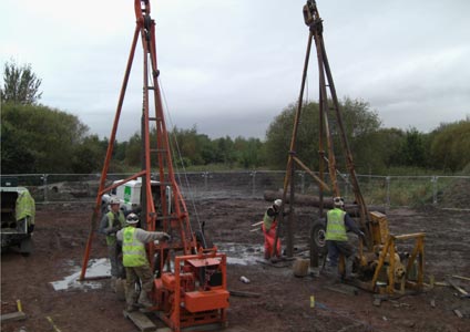
Figure 5 Wellpoints being installed via Cable Percussion Boring System (Ogi, 2015).
3.12 Retaining Wall Systems
3.12.1 Sheet Piling
Steel sheet piling is a well-known and well-understood technique of retaining wall construction. Steel sheets of varying lengths and profiles are either impacted or vibrated into the designed penetration in order to gain the required embedded depth. The joints amid sheet piles can be comparatively, but commonly not completely, waterproof. The addition of a water proofing sealant can decrease the extent of groundwater passing through, via the joints in the temporary state, whilst the joints will be welded above reduced level in the completed and permanent condition. Sheet piles penetrate almost every soil type, but largely cannot penetrate bedrock except if predrilling is assumed. While impact hammers generate a great amount of noise and vibration, contemporary high frequency vibrating hammers are utilised successfully in close quarters to already existing structures. Sheet piling is used regularly as a provisional retaining system, where the piles are removed when the complete/permanent basement structure is installed. Permanent unlined sheet pile walls have been utilised on a number of various basement projects in Dublin. Sheet piles also accommodate permanent axial loads.
3.12.2 Contiguous Piling
Contiguous piling systems largely includes the installation of in-situ concrete piles at distances of 1.5 to 3.0 times pile diameter apart. This form of retaining system is only appropriate in distinct soil types, where soil loss and groundwater penetration will be controlled or prevented. For example, the technique will be suitable for a construction site with clay from ground level to formation level, but is not appropriate where a water-bearing gravel is existing. It is vital to contemplate the likely presence of sand and gravel lenses and layers in clay deposits and to have alternative plans in place should these become known at construction stage. Contiguous piling can be installed in most every soil and rock categories, subject to appropriate installation equipment and plant. The piling is either temporary or can be combined into the completed structure to give retention and vertical load carrying competences.
3.12.3 Secant Piling
Secant piling includes the installation of concrete piles which intertwine and consequently provide a continuing concrete wall. The piles are installed in a soft-hard (more commonly) or hard-hard arrangement. The soft piles are installed primarily utilising a soft concrete mix, and these piles are generally not reinforced. When the hard piles are installed they secant into the soft piles on each side. The hard piles are created using structural concrete, and are reinforced. The hard piles consequently provide all the structural durability and rigour. Save for issues of tolerances, quality, and stratigraphy a secant pile wall provides an almost complete ground water cut-off in the temporary state. In the permanent condition a secant pile wall is to be considered to be “Type A” in accordance with BS8102. That is to say the construction itself does not deter water penetration. Protection is reliant on a total water or water and vapour barrier system applied internally or externally. As in keeping with contiguous piles, a secant pile wall will either be temporary or combined into the permanent structure.
3.12.4 King Post Walls
King Post Walls offer a financially inexpensive alternative when constructed in appropriate ground conditions. Essentially, King Post Walls comprise of the installation of a structural post (usually a UC or UB section) at varying distances apart, commonly 2m to 4m and in filling the void amid the posts with horizontally spanning material. This material can commonly be timber, steel or more often in-situ or precast concrete. Infilling between the King Posts is typically carried out in a topdown manner. Thus, the retained soil is needed to stand somewhat unsupported while the infill panel is being erected. King Posts can be installed by drilling a hole with a piling rig, which is generally recommended, or by excavating “slots” through a battered excavation. King post walls deliver only marginal waterproofing above formation level, and no groundwater cut-off below formation level. Ground movements with king post walls can be larger than with some of the systems previously mentioned, and therefore may not be suitable close to settlement with existing structures.
3.12.5 Diaphragm Walls
Diaphragm walling generally involves the creation of a trench via excavation utilising crane suspended “grabs” or milling cutters. The excavation is undertaken while the trench is filled with a support liquid, commonly a bentoite slurry. The diaphragm wall is created by filling the excavated trench with concrete which transfers the support fluid (Byrne, 2007).
3.13 Waterproofing Basements
3.13.1 Site preparation and the control of moisture
Control or comprehensive barring of moisture is one of the primary considerations when constructing a deep basement. On occasion, for example where the basement is not heated, the control of water vapour will be essential. Roughly all dampness occurs from the ingress of water. The focus on these three sections is to control the infiltration of groundwater, and/or rising damp. Water will be under substantial pressure when the water table is high. In principle, tankingof a basement necessitates that the walls and floor (and importantly the junction of the wall and floor) will be resist the ingress of water. However, on a comparatively dry site, drained cavity construction will be utilised as an alternate to tanking provided steps are taken to eliminate any water from a drainage channel. The building will be orientated and designed at the layout stage to circumvent the danger of growing hydrostatic pressure on the basement. Where this is not feasible and where there a possibility for a build-up of water pressure, the design will cover a complete hydrostatic head or provide a rod-able sub-ground drain to lessen hydrostatic pressure. The design specification will satisfy the projected end use for the basement, although any probable future modification in use will be measured, as it will be either very costly or not possible to upgrade the performance of the basement at a later point. BS 8102 gives four grades of basement use, together with acceptable forms of construction. See the table below:
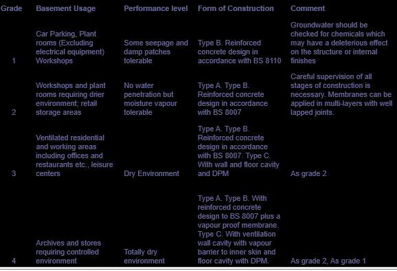
Figure 6 BS 8102 Guidance Table (trotman, 2007)
3.14.1 Type A: Tanked Protection Barrier System
Basement construction comprises a concrete slab and walls of reinforced concrete or blockwork with external, sandwiched or internal waterproofing. The structural waterproofing must be able to resist water that may be under hydrostatic pressure. Type A construction: when hydrostatic water pressure occurs. If blockwork is used for the walls, a cement rendering or flush pointing may be necessary to produce a satisfactory surface to receive the waterproofing. The basement is waterproofed via a membrane which is located either on the external, centre of the joint and internally. All three methods can be used in unison to ensure complete water tightness.

Figure 7 Type A Tanking System (British Cement Association, 1994)
3.14.2 Type B: Structural Integral System
The water tightness of the Type B construction is dependent upon the construction and design detail of the basement as a fundamental shell, utilising a concrete of low permeability and fitting joint specifics. Faults can be reduced by precise specification and design and by vigilant construction. The most general defects are permeable concrete and honeycombing through lack of compaction, contamination of, or cold construction joints and cracking due to thermal contraction and shrinkage.
Construction joints require specific consideration as these are the areas’ most notably associated with ingress. Whilst attention needs to be paid to jointing and final positioning of water stops, excessive care is required in the placing and compressing of the concrete.
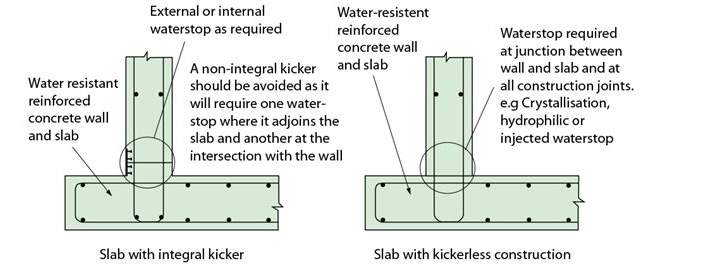
Figure 8 Type B Structural Integral Protection (British Cement Association, 1994)
3.14.3 Type C: Drained System
Type C construction is heavily dependent on water being counterattacked by the structural elements and any water that gains ingress to the external shell of the building being collected in a cavity created between the external wall and an internal wall. There is a perpetual reliance on this cavity to collect groundwater leakage and direct it to an appropriate discharge point. For example, drains or a sump for exclusion by gravity drainage or mechanical sump-pumping. The volume of free water incoming to the cavity will rely on the volume of external water, its hydrostatic pressure and on the resistance of the building itself to water access. Designers must consider any hazard associated with a continuous supply of probable contaminated water to the building. (British Cement Association, 1994).
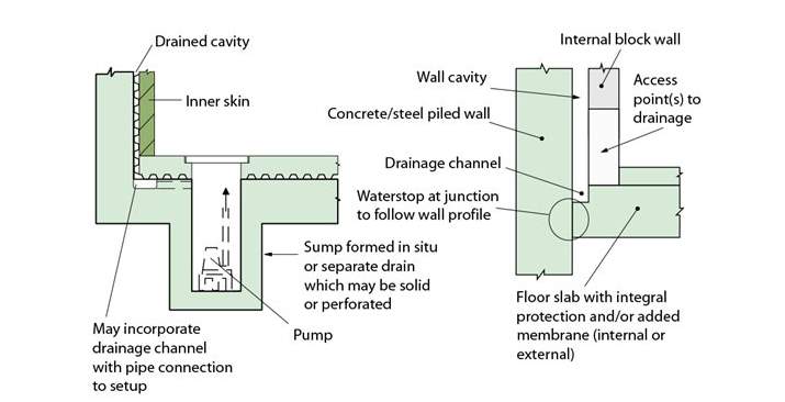
Figure 9 Type C Drained System (British Cement Association, 1994)
4. Case Study
Introduction
The aim of this chapter is to provide an elucidation to why the case study in question was prudently selected, it gives the reader a clear background on the requirements for a deep basement to be constructed as well as brief historical uses of the buildings that were demolished.
4.1 Background
| Client | Royal College of Surgeons Ireland |
| Architect | Henry J Lyons |
| Civil/Structural Engineers | O’Connor Sutton and Cronin |
| Building Height | Nine Storeys/46 Metres |
| Square Metres | 12,000 sq. metres |
Figure 10 Case Study Specifics
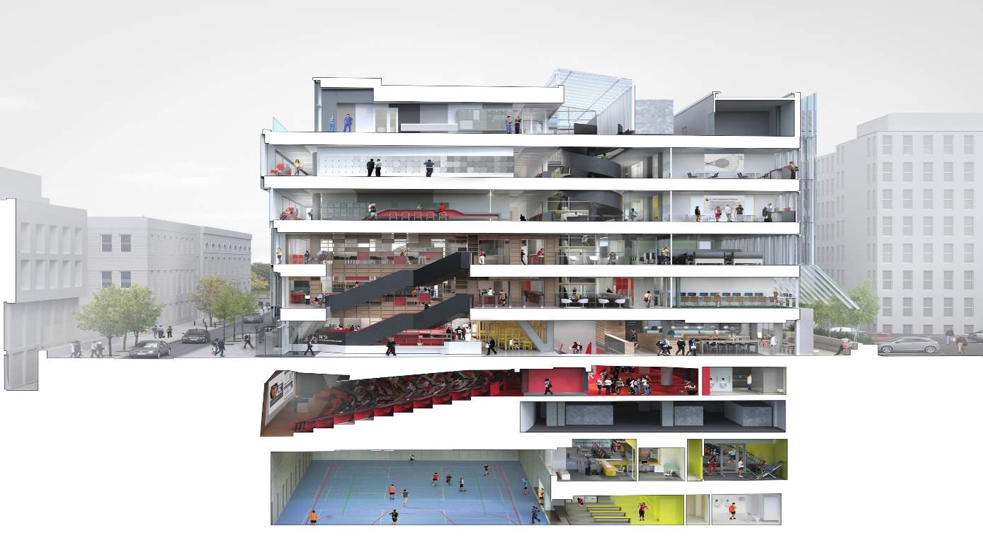
Figure 11 Architects model of the completed Building (HJL Architects, 2012)
In 2005, the Royal College of Surgeons Ireland purchased two buildings from Dublin City Council on York Street Dublin 2, the previous use of these buildings was social housing, these buildings were constructed in 1949 utilising a pastiche Georgian style façade. Prior to the buildings that were constructed in 1949 there stood Georgian three storey houses which were constructed in 1815, however, after the Act of Union, the terrace of Georgian houses progressively declined into tenements, housing numerous amounts of families in slum conditions. Due to quite dangerous crime, anti-social behaviour, health and safety issues, the situation became so dire that Dublin City Council ultimately demolished the street in 1947, and re-built more modern flats, sixty-six in all. The motive for the construction of such a deep basement is due to planning permission, Dublin City Council rejected permission for a ten-storey structure on York Street as it “far exceeded the height of any other structures sin the vicinity, and the building must be of similar height with existing structures in the vicinity”.
The New Advanced Academic Building was ultimatelyfour storeys in depth below ground and five storeys in height above ground level.
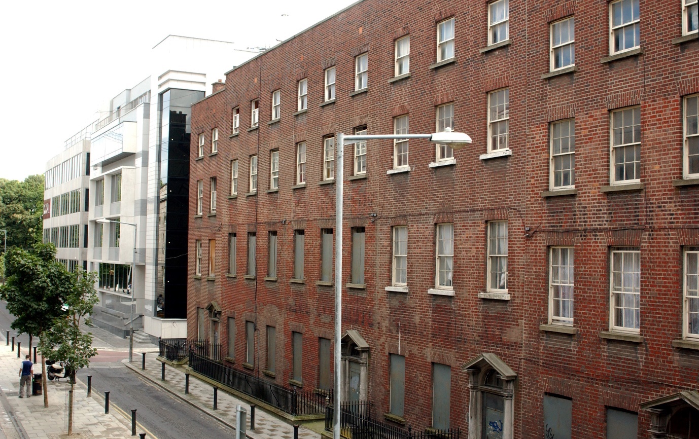
Figure 12 Buildings that were purchased by the Royal College of Surgeons Ireland (McNicholl, 2007)
4.2 Geotechnical Survey and Desktop Survey Undertaken
During the course of the geotechnical investigation and desktop survey it was quickly established that there was once an estuary to the river Liffey. The estuary was formerly known as the “Styne River” and flows directly behind the back of Figure XXX above. It was also discovered that although the river was culverted through local sewer systems it had an adverse effect on the water table, this was due to a suspected leak in the sewage system. This would later play a role in groundwater control, owing to the discovery strategies that were able to be put in place to manage any adverse effect this may have presented.
As par course of the desktop survey it was found that the gas mains and foul water/surface water sewage lines were located in the median of Cuffe Street road. These services required to be connected to as a source of natural gas and, additionally to connect to the sewage for the sanitary disposal of foul and surface water. This information was provided by Board Gais and Dublin City Council’s as built respective surveys. To ensure this information was correct a survey company was employed to undertake an investigation to establish the true location of the above-mentioned services. This survey was executed out of peak traffic flow hours, to assist the survey, an expensive road closure licence from Dublin City Council was granted.
The survey utilised radio-detection equipment, and as a direct resultant, it was established the true location of the gas mains and sewer lines. These services were found to be closer to the footpath, by almost two meters than described as the as built survey. To circumvent any time and expense related project delays it was decided to revise the route and connection point to all services. This was accomplished via a temporary route, which was then made a permanent route. This connection to the surface water would prove pivotal as it was an access point to alleviate the large volume of projected groundwater.
4.3 Water Table and Groundwater Control
On account of the basement being excavated to sixteen metres groundwater was invariably encountered, this fact was due to extremely high hydrostatic pressure from the water table. The groundwater ingress first began when the excavation reached four meters in depth, as the excavation became greater in depth, large volumes of water penetrated cracks in the rock, this phenomenon ceased at twelve meters. However, a suitable method of groundwater control was required, this was achieved by dewatering. The dewatering system was in the form of a wellpoint or commonly referred to as a “vacuum well”, in which water is allowed to enter several bore holes, 150mm in diameter and protected with a casing to prevent collapse. The water was then pumped out utilising a submerged pump and discharged into the localised surface sewer water system. While these was no access available to localised services the water was pumped into a large volume attenuation tank. One advantage of the attenuation tank was that small amounts of sediment would remain in the bottom of the tank and did not make its way into the waste water system. As fines can occur if such events take place.
Another noteworthy method used to control water ingress was the use of secant piled walls this is a “cut off” technique, the secant piles are reinforced with steel rebar or with steel beams and are created by drilling under mud or augering. Primary piles are installed first with secondary piles constructed in between primary piles once the latter gain designed strength. Pile overlap are characteristically in the order of eighty millimetres. This method is referred to as “male and female” secant pile wall. The piles were to a depth of eighteen metres. This method will not ensure 100% water ingress; it requires to be complimented with supplementary waterproofing systems.
4.4 Waterproofing Methods
After numerous design meetings had taken place, it was decided to use two water proofing techniques. The reasoning was that it is impossible to gain access to the secant piled walls after the retaining, reinforced concrete wall is constructed, so there is only a one-time opportunity to address water proofing. The types of water proofing utilised was Type A which is a “barrier protection” method, this is where a waterproof material is put in place and offers as a barrier to the passage of water. This waterproofing technique is dependent on preparation and the application of the structure that will be made waterproof. A high level of attention to detail is required as high hydrostatic pressures will allow water to ingress via the path of least resistance.
The second system to be used was Type B, structurally integral. The water tightness of the Type B construction is dependent upon the design and construction of the basement as an integral shell, using a concrete of low permeability, and appropriate joint detailing. Defects can be minimised by correct specification and design and by careful construction. Type B waterproofing must be installed in accord with the design by properly experienced and trained operatives who are fully conscious of the necessities for placing concrete used in Type B systems.
Both methods being utilised as a composite are, in general, not often heard of. The main reasoning being the end use of the lower half of the basement being a sports hall and gymnasium. It took in excess of eight months to ensure water tightness. This was due to high hydrostatic pressures, which assisted the ingress of water via cracks. Water resistant resins had to be pumped into cracks in the concrete caused by high pressures before the Type A tanking was applied.
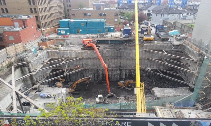
Figure 13 Basement at sixteen metres deep (McNicholl, 2007)
Chapter 5. Findings and Analysis
5. Introduction
This chapter discusses the data analysis and findings from qualitative research methods, it then compares research from the case study and literature review. Findings will be validated via triangulation, triangulation is a method of assuring the validity of research results through the use of a variety of investigation methods and approaches. Triangulation also allowed the researcher to collect qualitative data from both primary and secondary sources.
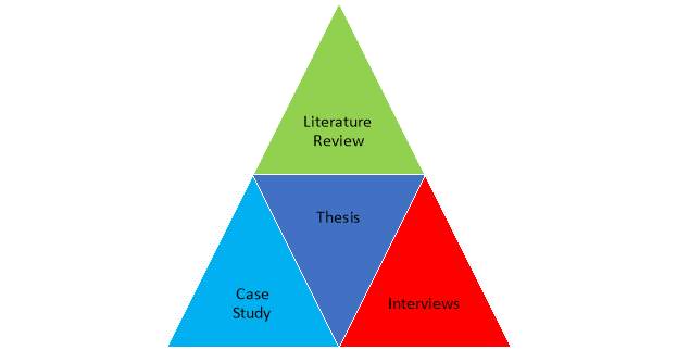
Figure 14 Thesis Findings Triangulation
These interviews took place across February and March of 2017, the study was conducted in the places of work of the interviewees, all located in Dublin City Centre. The persons who took part in the interviews had on average seventeen years’ experience constructing of deep basements in brown field sites, this was either in design process and project management or being a project manager for the main contractor.
The author conducted the study using the qualitative method of data gathering, this was carried out by asking eight questions in total. The questions were in the form structured and recall process. Every phenomenon mentioned had two questions associated, the first being structured, this allowed for the person being interviewed to understand what was being asked and relevance to the interview, the second question was recall/process, this allowed the interviewee to recall how they had dealt with previously encountered issues, or indeed avoided them in the first instance.
The ultimate aim of the questionnaire was to increase a further understanding on how seasoned construction project managers can identify issues before they arise, and how through a combination of composite, innovative techniques can lead to a watertight basement construction. This method would also incorporate the literature review, and case study to affirm findings and enable the author to publish his findings and subsequent analysis.
5.1 Findings Desktop Survey
Geocon states (insert ref) “The desktop survey assists to identify any possible significant features that may necessitate further investigation such as potential contamination sources for the purpose of ground conditions below a proposed structure. This survey also assists in identifying underground services such as: foul/surface water drainage systems, gas pipes, telecommunication cables and electrical cables. These services may very well be still live or inactive. A practical method of identifying the aforementioned services is to simply contact the service provider and requesting an underground network map”,
during the course of interview no.3 Ruairi Hayden concurs by stating “An example is a project in Tallaght where we had an old surface water drain but it was coming from an old site that was now derelict, it never became an issue as it was identified beforehand and diverted with permission”,
the finding was also solidified as Hayden also stated “Another example was an NTL project, again, we knew it (the services) was there but weren’t sure exactly where it was on site, this meant constructing a number of slit trenches to work out exactly where it was.”
It was also noted during the case study, after a through site reconnaissance which was complimented with a desktop survey of former uses of the site, it was established that an estuary to the river Liffey historically referred to as the river Styne leads was culverted into localised surface water sewage system. Great care was given to avoid damaging this sewage pipe during the excavation, as it would have allowed water to ingress causing waterproofing problems.
5.2 Findings Groundwater Control
Byrne states “Each time an excavation is completed underneath the natural water table, there is a danger that it may become unstable or overflow, except if measures are taken to govern the groundwater in the adjacent soil. Groundwater may be controlled by creating a physical barrier to reject groundwater from the excavation, or alternatively by pumping groundwater from specifically installed wells”,
during the course of interview no.1 McCarthy determined “Groundwater control really is pumping, this was the way, however, on one occasion we used sheet piling which would keep some water out but we would still have to use it in conjunction with pumping. This was during the excavation stage, we would let the water come in and then pump it out”.
While Lyons affirms, as per interview no. 3 “Mainly I’ve used well points this is a method of allowing water to egress into the site and remove via a sump pump”.
Research carried out by the author during the case study found that groundwater was first encountered at four metres in depth, this was controlled via using a well point system, well points were strategically placed around the excavation and pumped out mechanically and discharged into the surface water sewage system.
5.3 Findings Retaining Wall System
Byrne States “Secant piling includes the installation of concrete piles which intertwine and consequently provide a continuing concrete wall. The piles are installed in a soft-hard (more commonly) or hard-hard arrangement. The soft piles are installed primarily utilising a soft concrete mix, and these piles are generally not reinforced. When the hard piles are installed they secant into the soft piles on each side. The hard piles are created using structural concrete, and are reinforced. The hard piles consequently provide all the structural durability and rigour”,
Lyons asserted during interview no. 3 “The retaining wall system serves two purposes, firstly it acts as a cut-off point to prevent water gaining access to the basement. The second is to add support for the reinforced concrete wall that is constructed. The main considerations are forces applied, with the example of the New Advanced Education Building there was a Dublin City Council large multi-occupancy building right beside the excavation. With that in mind the decision was made to use male and female secant piled walls, for added support ground anchors were also used”. Hayden confirms by stating “In most situations I have been in we have use secant pile and contiguous pile walls”.
5.4 Findings Waterproofing
The British Cement Association advise “Control or comprehensive barring of moisture is one of the primary considerations when constructing a deep basement. On occasion, for example where the basement is not heated, the control of water vapour will be essential. Roughly all dampness occurs from the ingress of water. Water will be under substantial pressure when the water table is high. In principle, tankingof a basement necessitates that the walls and floor (and importantly the junction of the wall and floor) will be resist the ingress of water. However, on a comparatively dry site, drained cavity construction will be utilised as an alternate to tanking provided steps are taken to eliminate any water from a drainage channel”,
Lyons affirmed this by saying “The retaining wall system serves two purposes, firstly it acts as a cut-off point to prevent water gaining access to the basement. The second is to add support for the reinforced concrete wall that is constructed. The main considerations are forces applied, with the example of the New Advanced Education Building there was a Dublin City Council large multi-occupancy building right beside the excavation. With that in mind the decision was made to use male and female secant piled walls, for added support ground anchors were also used.”
To posit the literature review finding as well as Lyons postulation Hayden stated “In most situations I have been in we have use secant pile and contiguous pile walls. On a couple of occasions, we have used steel sheet piles on the construction of the tanks but only locally for one length of wall. In the basement in Tallaght we used king post walls and secant pile walls and soil nailing, there was a combination of different types dependant on space, cost and speed. We didn’t want to have stuff we’d need to go back on so pulling out steel sheet piles wasn’t really an option. We had the space to do it also, and this then allowed us to build one sided walls once we had our piles constructed.”
As further affirmation to the previous discoveries it was found during the research of the case study that secant piled walls were used, this is a “cut off” technique, and the secant piles are reinforced with steel rebar or with steel beams and are created by drilling under mud or augering. Primary piles are installed first with secondary piles constructed in between primary piles once the latter gain designed strength. Pile overlap are characteristically in the order of eighty millimetres.
5.5 Analysis
The method of evaluating data using is the analytical and logical reasoning to examine each constituent of the given data. This variety of analysis is just one of the many steps that is to be completed when conducting qualitative research. Data from varying sources is gathered, studied, and then analysed to form some variety of result or conclusion. There are a variety of specific data analysis methods, some of which include data mining, text analytics, business intelligence, and data visualizations. (Glynn, 2017)
5.6 Desktop Survey Analysis
For the question: After a thorough desktop survey has been undertaken trying to establish the existence or location of underground services, have any other unidentified services been discovered after the excavation of the basement has begun? All respondents had carried out a desktop survey on various projects – this helped to establish underground services. With the case study the desktop survey assisted to establish the existence on an underground estuary. The general attitude towards the desktop survey was a positive one as it can ultimately save time on the planning element of the project – though McCarthy stated, “What I found especially in inner city locations that there is any number of services that aren’t documented and you discover them along the way”
5.7 Groundwater Control Analysis
From the question: Have you ever encountered ground water, if so what method(s) did you employ to prevent water egression into the basement excavation? All interviewees responded yes, the method of control was to always utilise a pumping method, however McCarthy and Lyons both stated that they had used an alternative approach of groundwater control, this method was to freeze the ground and ground water, whilst Hayden had only ever used the well point pumping method.
5.8 Retaining Wall System Analysis
From the question: What is the main consideration when deciding on what retaining wall system is employed? All respondents had a very positive attitude towards the secant piled wall system, this was due to the fact is acted as a cut off point for water ingress and also acted as a structural aid to the reinforced concrete wall system that would be installed after waterproofing occurred. As per the case study it was also found that ground anchors were also utilised to aid with soil retention.
5.9 Waterproofing Analysis
From the question: Have you ever used a combination of types A, B, C to ensure water tightness has been achieved, if so what combination and why were these selected? Respondents attitude towards the subject was one of positivity as they had all utilised all types, type a being the most popular as this is mainly utilised for underground carparks. However, Lyons stated to ensure the complete weather tightness of the NAEB at the design stage, due to a very high water table and large hydrostatic pressures it was decided to use a combination of type A tanked protection and type B structural integral protection this “above and beyond the norms of ensuring water tightness”
Overall the general attitudes of the participants were varying, all interviewees had differing experiences of different projects. Most notably the end use of the basements that were to be constructed and then made watertight. Common themes that kept on merging have been highlighted and addressed from 5.6 to 5.9
References
Boodhoo, R., 2009. http://www.nyu.edu/classes/keefer/waoe/deeprosh2.pdf. [Online] Available at: http://www.nyu.edu/classes/keefer/waoe/deeprosh2.pdf [Accessed 20 Febuary 2017].
British Cement Association, 1994. Basement Waterproofing. Gesign Guide For Basement Waterproofing, 1(1), p. 19.
British Standards, 2013. http://0-www.ihsti.com.ditlib.dit.ie/tempimg/154539E-CIS888614800305063.pdf. [Online] Available at: http://0-www.ihsti.com.ditlib.dit.ie/tempimg/154539E-CIS888614800305063.pdf
[Accessed 05 March 2017].
Buildcost, 2012. https://app.mediahq.com/files/pr/smr39088_%5B1%5D_Buildcost%20Construction%20Cost%20Guide%20-%20Second%20Half%202012.pdf. [Online] Available at: https://app.mediahq.com/files/pr/smr39088_%5B1%5D_Buildcost%20Construction%20Cost%20Guide%20-%20Second%20Half%202012.pdf [Accessed 20th Febuary 2017].
Buildcost, 2016. www.buildcost.ie. [Online] Available at: http://buildcost.ie/wp-content/uploads/2016/02/Buildcost-Construction-Cost-Guide-First-Half-2016-1.pdf [Accessed 20 Febuary 2017].
Byrne, J., 2007. Geotechnical Design Aspects of Basement Retaining Walls. Geotechnical Design Aspects of Basement Retaining Walls, 1(1), p. 23.
Clayton, J., 1995. The Standard Penetration test. The Standard Penetration test, 1(1), p. 143.
Dando, 2016. http://www.dando.co.uk/geotechnical/dando-2500. [Online] Available at: http://www.dando.co.uk/geotechnical/dando-2500 [Accessed 8 March 2017].
Geocon, 2017. http://www.geoconsiteinvestigations.com/environmental-consultant/phase-i-site-investigation. [Online] Available at: http://www.geoconsiteinvestigations.com/environmental-consultant/phase-i-site-investigation [Accessed 6 March 2017].
Geotechdata, 2017. http://www.geotechdata.info/geotest/standard-penetration-test.html. [Online] Available at: http://www.geotechdata.info/geotest/standard-penetration-test.html [Accessed 8 March 2017].
Glynn, J., 2017. http://www.businessdictionary.com/definition/data-analysis.html. [Online] Available at: http://www.businessdictionary.com/definition/data-analysis.html [Accessed 11 April 2017].
Government TGD, 2004. http://www.housing.gov.ie. [Online] Available at: http://www.housing.gov.ie [Accessed 23 Febuary 2017].
HJL Architects, 2012. NAEB , Dublin: HJL.
Kowalczyk, D., 2015. Defining Primary and Secondary Research. Defining Primary and Secondary Research, 1(1), p. 3.
M. Easwaramoorthy, F. Z., 2006. INTERVIEWING FOR RESEARCH. INTERVIEWING FOR RESEARCH, 1(1), p. 6.
McNicholl, 2007. York Street , Dublin : Royal College of Surgeons Ireland .
Ogi, 2015. http://www.ogi.co.uk. [Online] Available at: http://www.ogi.co.uk [Accessed 10 March 2017].
Oxford English Dictionary, 2017. www.oxfordlearnersdictionaries.com. [Online] Available at: http://www.oxfordlearnersdictionaries.com/us/definition/english/basement?q=basement [Accessed 19 April 2017].
Spillane, C., 2016. PECIFICATION AND RELATED DOCUMENTS FOR GROUND INVESTIGATION IN IRELAND. PECIFICATION AND RELATED DOCUMENTS FOR GROUND INVESTIGATION IN IRELAND, 1(1), p. 174.
trotman, P., 2007. Site Investigation and preperation. Site Investigation and preperation , 1(1), p. 8.
W Preene, T. R. W. P., 2016. Ground Water Control Design. Ground Water Control Design Second Edition, 1(1), p. 185.
Cite This Work
To export a reference to this article please select a referencing stye below:
Related Services
View all


Related Content
All TagsContent relating to: "Technology"
Technology can be described as the use of scientific and advanced knowledge to meet the requirements of humans. Technology is continuously developing, and is used in almost all aspects of life.
Related Articles

DMCA / Removal Request
If you are the original writer of this dissertation and no longer wish to have your work published on the UKDiss.com website then please: