Design of a Compressed Air Supply System for a Factory
Info: 8792 words (35 pages) Dissertation
Published: 15th Dec 2021
Tagged: Engineering
Contents
Click to expand Contents
Introduction
Task division
Question 1
Load Definition
Table 1
Forge dimensions
Table 2
Total load on and off peak
Figure 1
Question 2
Figure 2
Compressor Selection
Table 3
Volumetric Efficiency for Air Compressor
Question 3
The Volume Receiver
Receiver Pressure Versus Time Graph
Question 4
After Cooler
Table 4
Question 5
Pressure Relief Devices
Figure 4
Figure 5
Mild Fire Situation
Figure 6
Figure 7
Figure 6
Figure 8
Figure 9
Severe Fire Circumstance
Figure 10
Figure 11
References:
Appendices
Appendix A:
Appendix A.1. (Lecture week 2)
Appendix A.2. (Lecture week 3)
Appendix B
Appendix C
Appendix D
Appendix E
Appendix F
Appendix G
Appendix H
Introduction
This project focuses on the designing of a compressed air supply system for a factory. Designing this proper compressed air in a factory to recourse its utilization is the main objective for this project. Additionally, this project gives a brief introduction to factory’s requirements in terms of air compressor design such as this air compressor is to run in many kinds of tools like a pneumatic riveter, spray painters, hoists performance, etc. Mostly tools that have a property of air motor driver and somehow these applications are not quite efficient regarding their performance in the factory.
The purposes for this project as it’s recalled earlier from the previous paragraph will be elaborated further in details, as the student will work in pair because they need to work with their student numbers consecutively, to provide a supply air compressor design, also this project is parted in two sections of part A and part B. This paper will individually discuss the questions from part A only. For part A, this project is to answers 5 questions in total; therefore, the first thing to do is to define the load profile from different kinds of area of operation. Areas of operation indicate the forge that comprises an operated hammer 1 double acting cylinder, one end only piston rod, bore, piston rod, and stroke. All comes with dimensions that will be mentioned later in the next few paragraphs. Others operation tools are the fettling shop, machine shop, assembly shop, paint spray shop, electroplating shop and packaging department. The consumption rate of airflow is given independently for each tool, thus associated with the last digits of the student number to be used. Right after finishing all the 5 questions in this part A, students are be able to go on to start part B that includes the piping design and the pressure vessel. These are where the power output acquired from air distribution to each tool to operate properly.
Question 1
Load Definition
In this part, the project partners number are in variables of X and Y, therefore as the discussion is made by each partner with Y as his/her family name’s first letter that is close to the end of alphabet and X as the family name’s first letter that close to the beginning of alphabet. These are the requirements to start the load definition for each tool at each shop.
Partner 1: Michael Lim – s3543066 = Y
Partner 2: Timothy Daren – s3498359 = X
Sample calculations below are derived to answer each of every tool. For example, the fettling shop that has:
Grinders
One grinder operates and uses 25.0 + (Y/0.7) liters/sec of air. Y is the student number of Michael Lim of 6. Therefore, by knowing the quantity of grinders with the load factor, the total air consumption can be obtained:
N (number of grinders) = 14 units
L (Load factor in %) = 50%
Y = 6
[25.0+(Y/0.7)] x N x L = [25.0+(6/0.7)] x 14 x 50% = 235 l/s
Chippers
A chipper here uses 18.0 – (Y/0.6) at full running load. However, by using the same exact formulae to get the air consumption (liters/sec), it can be formulated as:
N (number of chippers) = 12 units
L (Load factor in %) = 50%
Y = 6
[18.0 – (6/0.6)] x 12 x 50% = 48 l/s
Hoists
The hoists here use 20 liters/sec at full load, therefore the total air consumption of hoists can be calculated as:
N (Number of hoists) = 3
L (Load factor in %) = 10%
20 x 3 x 10% = 6 l/s
Furthermore, next step will be the forge analysis to get the amount of volume rate. Things that will be considered to obtain the total of the forge demand for volume rate is to get the volume of the cylinder up stroke and down stroke. Both of up and down strokes are 8 times. The forge details for its dimensions are:
| Forge | |||
| Category | Dimensions | Units | |
| Bore diameter (Db) | 450 | mm | |
| Piston diameter (DP) | 110 | mm | |
| Stroke length | 855 | mm | |
| Cycle | |||
| Up strokes | 8 | ||
| Down strokes | 8 | ||
Table 1
Forge dimensions
Thus, the calculations will be as:
Volume of cylinder upstroke will be given as follow:
V̇T = volume of the compressed air
101.3 kPa x V̇
a =
590 kPa+101.3 kPa x [8 x 0.13598 m3] +
(8 x 0.12785 m3)
V̇
a = 14.4036 m3/time (seconds)
The peak time is happening at 1.5 minutes, therefore by knowing the volume of 14.4036 m3 above, the volume rate can be obtained as follow:
V̇
a = 14.4036 m3/90 seconds = 0.16004 m3/sec or 160.04 liters/second
In finding the required amount of the identical volume rate for the atmospheric pressure of Pa it uses the perfect gas law equation. With the units used here usually in liters/sec, m3/min and cubic feet per minute. It does show the connected relationships mathematically in a way on how this result is obtained.
The entire above sample calculations for the fettling shop that contains grinders, chippers, and hoists are to be followed by other tools at different shops will be tabulated below:
| Tool | Quantity [no] | Air consumption [L/s] | Load factor [%] | Total usage [L/s] |
| Fettling shop | ||||
| Grinder | 14 | 33.57142857 | 0.5 | 235 |
| Chipper | 12 | 8 | 0.5 | 48 |
| Hoist | 3 | 20 | 0.1 | 6 |
| Machine shop | ||||
| Blowguns, air chucks, air vices | 1 | 48 | 0.5 | 24 |
| Assembly shop | ||||
| Small screwdriver | 50 | 6 | 0.2 | 60 |
| Nut setters | 6 | 20 | 0.25 | 30 |
| Steel drills | 8 | 7.5 | 0.25 | 15 |
| Paint shop | ||||
| Polisher | 20 | 8.8 | 0.25 | 44 |
| Spray paint guns | 15 | 3 | 0.4 | 18 |
| Spray painting mask | 15 | 3 | 0.4 | 18 |
| Packaging department | ||||
| Wood borer | 5 | 16 | 0.3 | 24 |
| Large screw drivers | 5 | 14 | 0.2 | 14 |
| Hoist | 2 | 20 | 0.1 | 4 |
| Extra leakage | ||||
| 1 | 50 | 1 | 50 | |
| Off peak total | 590 | |||
| Forge volume flow rate obtained | 160.0045 | |||
| On peak total | 750.0045 | |||
Table 2
Total load on and off peak
In total of the on peak volume rate, it is the total off peak plus the forge volume flow rate as in the table discussed. With the total air consumption flow rate in liters/second, respectively of 590 L/s off peak and 750.0045 L/s on peak it can be determined to get the load profile graph whether it is on and off peak for the duration of 1.5 minutes on peak then 4.5 minutes off peak, repeatedly for 30 minutes duration. However, in order to maintain the on peak, and also the off peak, it is very important to get the minimum value of the compressor to distribute air to each tool. To get the minimum compressor requirement that is the horizontal line in the graph below, it is necessarily demonstrated in mathematical equations shown as:
Details known:
On peak = 750.0045 L/s at 1.5 minutes
Off peak = 590 L/s at 4.5 minutes
Minimum air compressor requirement =
750.0045Ls x 1.5 minutes x 60 sec+ 590Ls x 4.5 minutes x 60 sec=226800.405 litres
The cycle happens in every 6 minutes of the total time on and off peak, thus it is divided with the 6 minutes duration of time, which is:
226800.405 litres6 minutes*60 seconds
= 630.001125 liters/second
After found out the minimum requirement of air compressor of 630.001125 L/s above, it can be added to the graph as the new red trend to indicate that this minimum requirement is between the on peak and off peak, it is because that the amount of the air compressor supply cannot provide amount of 750.0045 L/s and also whenever there is off peak at 590 L/s of the demand. To come up with this, the minimum requirement of 630.001125 L/s is the ideal volume rate to supply the demand, which is the on peak occurrence of 750.0045 L/s and taking the storage that technically oversupply at off peak 590 L/s. The graph is shown as follow.
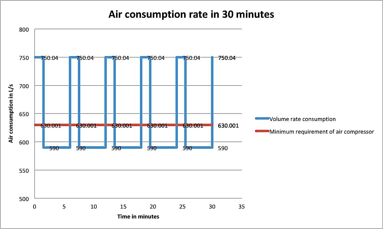
Figure 1: Air consumption rate over 30 minutes
Moreover, the following question is to commonly discuss the compressor selection, as the compressor should fit the peak flow requirements. Technically it is should be able to operate for short time even. In terms of cost, the compressor will need a quite amount of capital expenditure. Selecting the compressor for this factory needs to be carefully taken; it is risky and lead to unwanted outcome such as the voltage drops, overcharging current and high sound annoyance. It is essential to conduct a design that minimum electrical demand, with a combination of a receiver design to accomplish this.
Question 2
To select a compressor that will compatible to the peak flow necessity based on the graph figure 1, also it is applicable to the receiver that will be chosen later on in the next few paragraphs. By referencing to the free air delivery (FAD) that is to be calculated in this part, then the compressor selection from chapter 2 appendix 2A will be satisfied. Calculating the FAD from the minimum air compressor supply from the graph in figure 1 is recalled as 630.001125 L/s as the delivery capability. However, there is this condition that assuming 5% of decay in the future chance. Converting 630.001125 L/s to m3/min because of the units that is available in the appendix 2A as follow
630.001125 L1000 m^3 x 60 minutes x 0.95=35.910064 m3/min
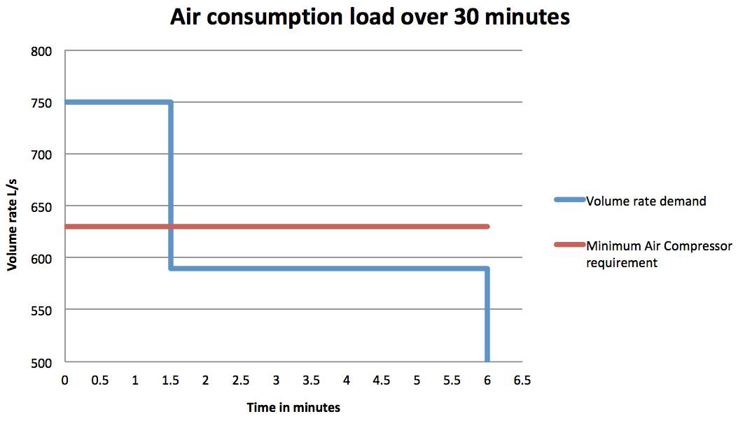
Figure 2: Load profile graph for volume rate demand and minimum air compressor requirements
Compressor Selection
After having the results of the minimum air compressor free air delivery needs, the compressor is selected as:
ER - Two Stages – Compressor (E7 and E8)
From those two compressors of E7 and E8, it is chosen to be E7 two stage compressor due to some reasons in technical that indicates the amount of FAD (Free Air Delivery). The FAD in E7 is shown in the table 2 below, it is 40.5 m3/min, where E8 has 63.0 m3/min. E8 compressor here has more of room to run the FAD, nonetheless the requirement of the minimum of air compressed supply is 35.910064 m3/min, which is enough to get E7. Additionally, it is good enough to supply 35.910064 m3/min, rather than E8 that is too excessively oversupply. In terms of the energy conservative, the smaller size of the compressor E7 is more conservative in energy for instance the water consumption for cooling is lesser than E8; also its efficiency is pretty well, considering also the running section of the load flow in the factory based on the graph that will analyze the costing, it is hypothetically to assume that the E7 will cost less than E8 compressor. Besides, there will be no tool that is extra to be added in the factory, getting a compressor that comes up a large volume of air delivery is such a waste as well. Have a look at the differences of E7 and E8 compressor’s properties below:
ER Type CompressorTwo Stage, Double Acting two cylinder |
|
| ER7 | ER8 |
|
|
Table 3: Mechanical properties of ER7 and ER8 compressors comparisons
The reason of choosing the ER type compressor is because of the two-stage cylinder double acting. This type of compressor also has more than 20 m3/min in its performance to deliver free air. Others type of compressors are not compatible regarding to what this project part A type’s selection. For example, like BE/IE type of compressor is one stage with low pressure, and DR two stage compressor maximally only reaches up to 21.9 m3/min. To what the requirement for the FAD according to the peak flow is at least more than 37.8 m3/min. Therefore, after comparing ER7 and ER8 in general; the appropriate selection for this project’s compressor would be ER7 compressor in terms of its overall capacity for FAD mainly. For more information for both specifications, see Appendix A.
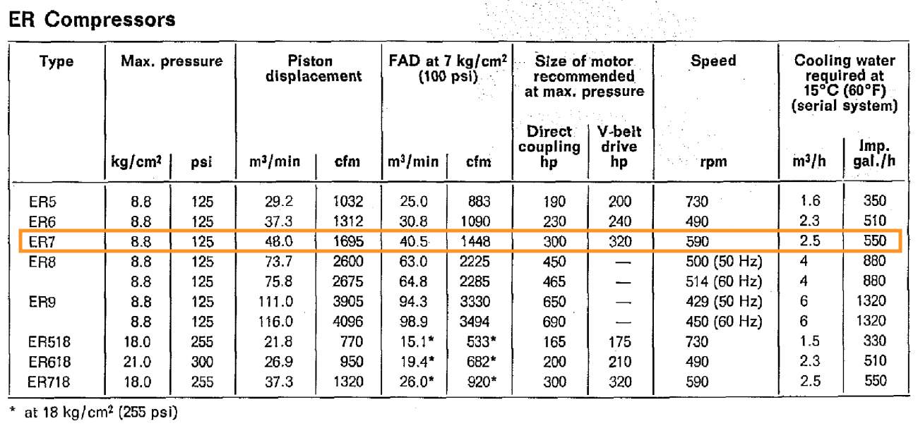
Volumetric Efficiency for Air Compressor
Moving on to the efficiency of the volumetric for the air compressor that is chosen (E7 Two stage compressor). By using the formula of the volumetric efficiency below (See Appendix A.1, based on Mechanical Design 2 Lecture week 2):
ηV= Vinduced m3/minutes/V̇sweptm3/minutes
Based on the information from table 3 for ER compressor comparison in mechanical properties, it will calculate for the volumetric efficiency for ER7 compressor by knowing the Vinduced and Vswept.
Vinduced = 40.5 m3/min
Vswept = 48.0 m3/min
V =
40.548.0 x 100%=84.375%
The volumetric efficiency for each of ER compressor is relatively similar; to compare with ER7 let’s take an example for ER8,
Vinduced = 63.0 m3/min
Vswept = 73.7 m3/min
V =
6373.7 x 100%=85.841%
It is quite similar for the efficiencies in both compressors, although the ER8’s volumetric efficiency is slightly higher than ER7, but it is not necessarily required to satisfy the requirement for this project and it will not affect much, for what the amount of FAD in this project is 35.910064 m3/min. It would be overabundant in fact that ER8 has 63 m3/min, that’s why using ER7 with 40.5 m3/min is very close enough to what we have for the required FAD.
Question 3
The Volume Receiver
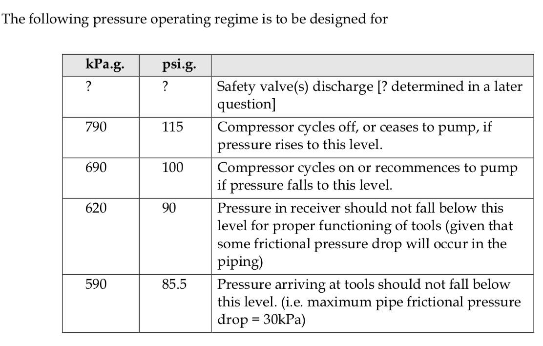
Now in question 3 it is very important to get the correct capacity of volume receiver, for the compressor that has been selected previously on question 2. Basically, a receiver is a system installed in air compressor to reduce amount of pressure palpitation and separate oil with water in air mist form. Especially it is also to supply a storage capacity as a reservoir during a peak load times. In a specific condition the pressure in the receiver should not fall below 620 kPa and it is also to subsist the peak occurrence by the forge. To get the volume of receiver or in symbolic form of VRR, it is obliged to equate by using the formulae of (See Appendix A.2, from Mech Design 2 lecture week 3):
Patmosphere(V̇inlet-V̇outlet)∆time=Pinlet-PoutletVRR
To indicate further in details for each symbol, hence:
- Patmosphere is the Pressure of the atmosphere that is 101.3 kPa
- V̇inlet is the volume that enters the receiver in L/s
- V̇outlet is the volume that exits the receiver in L/s
- Then delta time is the difference or the time intervals when the peak happens in seconds
- Pinlet is the pressure that comes to the receiver initially in kPa
- Poutlet is the pressure that exits the receiver or the final pressure in kPa
- VRR is the volume of the receiver in Litres
Firstly, the volume of receiver is to be equated in the formulae above as follow when the compressor is new particularly which states that the compressor is fully operative at 100% circumstance. The volume flow rate inlet above is the ER7 compressor of FAD 40.5 m3/min and the volume flow rate outlet is the on-peak air consumption flow of 750.0045 L/s. At the time difference of 1.5 minutes which will in 90 seconds.
Converting the flow volume rate inlet of 40.5 m3/min to L/s = 675 L/s
101.3 kPa(675Ls-750.0045Ls)90 sec=620 kPa-690 kPaVRR
VRR = 9768.800379 Litres
Secondly, the volume of receiver at decay condition 5% of capacity delivery. It shows that only 95% of the volume flow rate inlet is able to deliver optimally. With all the same parameters and also the same formulae, thus the amount VRR becomes:
101.3 kPa[(0.95 x 675Ls-750.0045Ls]90 sec=620 kPa-690 kPaVRR
VRR = 14164.496807 Litres
As we can see the amount of volume here of the receiver on the right-hand side of the calculation should be the same with the left-hand side of the difference in the total results. With lower kPa (pressure), it generates more volume, means the difference of inlet and outlet volume rate at 101.3 kPa in 90 seconds time. Inversely proportional to the right-hand side that the total of VRR is much lower because the pressure (kPa) is 6 times higher than the left-hand side at atmospheric state. Thus, they both share the same amount of volume rate (L/sec) at certain time (seconds) and compatibly equal to the total volume (in Litres).
Receiver Pressure Versus Time Graph
Considering the capability of the receiver to avoid the compressor’s stop and start. Here is to assume the main objective in this part is to control the start and stop and monitor the possible compressor for holding the valve so that the compressor will stop to compress air and to pump it through the receiver. After obtaining the volume of receiver above, it is now to calculate the on and off time span, and now is to calculate the mean of air demand during the forge peak soothes and also the current forge peak conduct. Finally, the graph showing the receiver pressure versus time can be drawn.
In 30 minutes, the amount of pressure and time will be elaborated below as using the formula in the question 3a when finding the volume receiver. Each of calculation will be performed as follow since the beginning of the cycle and so on. Also it is to compute the compressor’s span for on and off time.
Firstly, the compressor starts at the new state of 690 kPa.g (where the compressor restarts again, and the forge initialize). These calculations are pertinent similarly just like in the previous section where to find the VRR, but here we will have to find the pressure for each of time running. Restriction of the operating regime seen from Appendix C.
The below calculations for the first 6 minutes of the 30-minute cycle:
The rest of the calculations for the 30-minute cycle will be found at appendices H.
Moving on to the calculations for each step to get the pressure in receiver as follow:
Starting at 690 kPa as the initial state of the receiver
This calculation is of the first 90 seconds when the compressor is on at peak time.
101.3 kPa (675L/s – 750.0045L/s) (90 seconds) = (P2 – 690 kPa) (14164.496807 m3)
P2 = 641.723239 kPa
Due to the receiver exceeding 790 kPa as specific maximum pressure within the off-peak time, the compressor ceases to pump. Therefore, the time where receiver will reach 790 kPa is required to be calculated.
101.3 kPa (675L/s – 590L/s) (t) = (790 – 641.723239 kPa) (14164.496807 m3)
t = 244.643647 seconds
Moreover, at this stage the compressor resumes to pump the pressure fails at this level of 690 kPa
101.3 kPa (0 – 590L/s) (t) = (690 kPa – 790 kPa) (14164.496807 m3)
t = 23.699528 seconds
Remainder = 1.656 seconds
101.3 kPa (675L/s – 590L/s) (1.656 seconds) = (P2 – 690 kPa) (14164.496807 m3)
P2 = 691.007171 kPa
Below in the following page, depicts the plotted pressure versus time graph of the internal pressure of the receiver during the operational cycle of 30 minutes. From the graph, it can be shown that the total time when the compressor gets turned off is 1.9749961 minutes or 1 minute and 58.5 seconds, during the time periods which the pressure goes from 790 kPa to 690 kPa. Which results in a total run time of 28 minutes and 1.5 seconds. Thus, the overall running optimally running for 93.42% of the time.
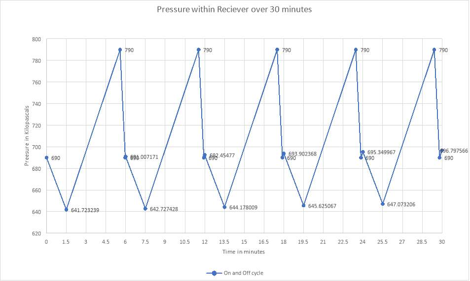
Figure 3: Pressure versus time graph
Question 4
After Cooler
Having done doing question number 3, for this section (Question 4) it is much more focusing on the cooling air apparatus. To reduce the compression’s work, it usually uses an air-based coolant or a water-based coolant. Also, to enhance the efficiency of volumetric is done by several steps. Air coolant acts to minimize the voluntary occurrence of hot air combustion.
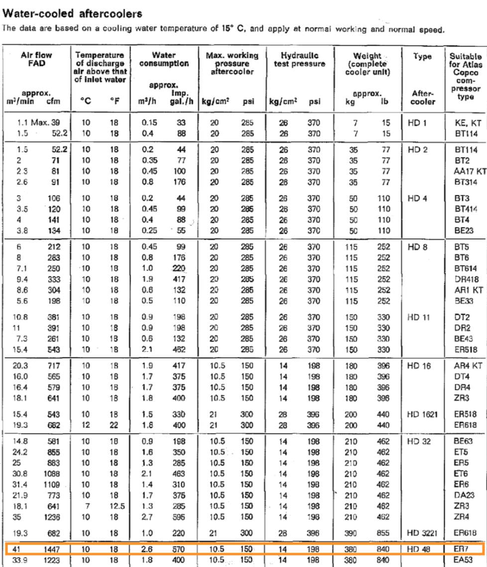
From the compressor that has been selected previously, the air-cooler selection will be chosen as HD48 after cooler and it is water-cooler type. This mainly because that the air cooler is compatible with the chosen compressor in terms of its mechanical properties, the FAD of 41 m3/min, which is suitable for ER7 Compressor that has 40.5 m3/min for its FSD. It is also mentioned that this after-cooler HD48 is suitable for compressor ER7 in the catalogue. These Water-cooler properties are listed in the table. See Appendix B.
| HD48 After Cooler | |
| Air flow FAD | 41.0 m3/min |
| Temperature of discharge air above the inlet | 10 C |
| Water consumption | 2.6 m3/h |
| Max pressure | 150 psi |
| Hydraulic pressure | 198 psi |
Table 4
After-cooler properties
To equate the water temperature at when the air exits it will require using the formulae of:
Tout=Tin+TD
Where,
Tout is the temperature where the water exits
Tin is where the temperature of water comes in
TD is the discharge air above the inlet temperature
Tout=15°C+10°C
Tout = 25 C
The temperature which the air exits the after cooler is 25oC.
Recalling that the factory has an electroplating shop that has volume rate of air 5.5 m3/hour of water at a temperature of 70 Celsius. So by formulating the heat transfer calculation to get the amount of power or
Q̇.
Q̇
=
ṁCp(Temp)
Knowing that the volume rate should be converted into kg/s, so it becomes
ṁ=
5.5 m3/hour = 1.527778 kg/sec as the flow rate of mass
Temp = 70 C – 15 C = 55 C as the temperature differences
Cp = 4.1855 J/(kg.K) as the specific heat
Inserting all the values into the
Q̇ =
1.527778kgsec x 4.1855Jkg.K x 70°-15°equation will result in:
Q̇=351.698264 kW
Looking at the power output from the ER7 to know the electric motor running the compressor. Converting hp to kW. Considering the operating time in percentage with the on-peak and off-peak time.
On peak 28.025039 minutes
Off-peak 1.974961 minutes
28.025039 minutes30 minutes x 100%=93.42%
1 hp = 745.7 Watts
Wout=300 hp x 0.9342 =280.25039 hp
The efficiency for the electric motor is equal to 93% or 0.93. Obtaining the amount of Wout by the efficiency at 100%.
Actual Wout =
280.25039 hp0.93=301.344505 hp
Convert into kW = 224.712597 kW
Considering the Energy Conservation Programs that the actual provided heat energy is identically 80% in equal. However, based on this statement the final output for the power in the Wout is:
WOutActual=0.8 x 224.712597 kW=179.770078 kW
Percentage of heat that is scavenged from the values above would be:
Heat scavenged =
179.770078 kW351.698264 kW x 100%=51.11%
To find the minimum kW rating of any supplementary heater that may be require is difference between the total amount of heat transferred by the actual amount of heat transfer by the shaft which can be scavenged.
Total heat transfer-Actual heat transfer=Minimum supplementary heater
Q̇-WOutActual=Heatersupplementary
351.698264-179.770078=171.927488 kW
Thus, the minimum supplementary heater need is 171.927488 kW.
Question 5
Pressure Relief Devices
Compressible gases can lead to a sudden blow and very dangerous due to overheating. Choosing the proper control systems to evade the source that creates the pressure rise is disabled when the pressure attains the upper limit. A pressure vessel encounters the pressure escalation if uncovered to the heat source like fire. It is importantly to be fit with valve system that can allow enough air out to prevent an unwanted extreme incident.
From looking at Appendix 3A in the lecture notes chapter 3, that discusses everything about the valve, it is crucial to cope a valve which is safe enough to prevent the receiver to receive an excessive amount of pressure delivered by the compressor pressure control in case it fails. It is applicable to read the clauses from AS1210 2010. By using the clauses from Australian Standard, for each requirement to answer the following questions as references.
In this case, the maximum temperature where the pump stops is at 790 kPa based on the pressure operating system (see Appendix C). Besides, that the selected compressor in this project is ER7 that has 125 psi in maximum temperature. Converting 125 psi to kPa units becomes:
1 psi = 6.89476 kPa
Compressor pressure maximum = 125 psi = 861.844662 kPa
For this reason, the maximum capacity of pressure that the compressor can hold up is up to 861.44662 kPa. If in a single event the pressure reaches more than 861.44662 kPa, the compressor will shut down and it is dangerous.
- The design pressure operating is at 790 kPa
- Maximum compressor pressure is 125 psi or 861.44662 kPa
The set pressure for this relief vessel is going to be 861.845 kPa as a maximum pressure similarly taken from the maximum compressor pressure. Furthermore the set pressure from the safety valve is chosen at 861.845 kPa.
The reason to put 861.844662 kPa as the set pressure in this project is because that:
861.845 kPa790 kPa x 100%=9.09421%
9.094% here is the margin between 5%-10% for the safety valve pressure increased. Refer to figure 5 below for the graph in a condition between 5%-10% margin above the operating temperature.
According to clause 8.2.1 that the upper limit pressure is to be necessarily designed 110% based on the set pressure as the protection from rising.
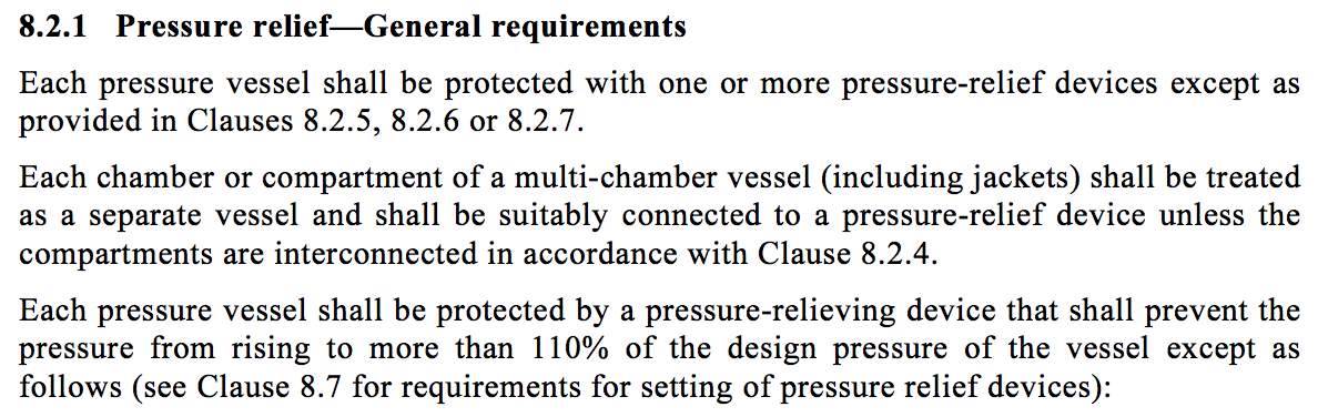
Figure 4
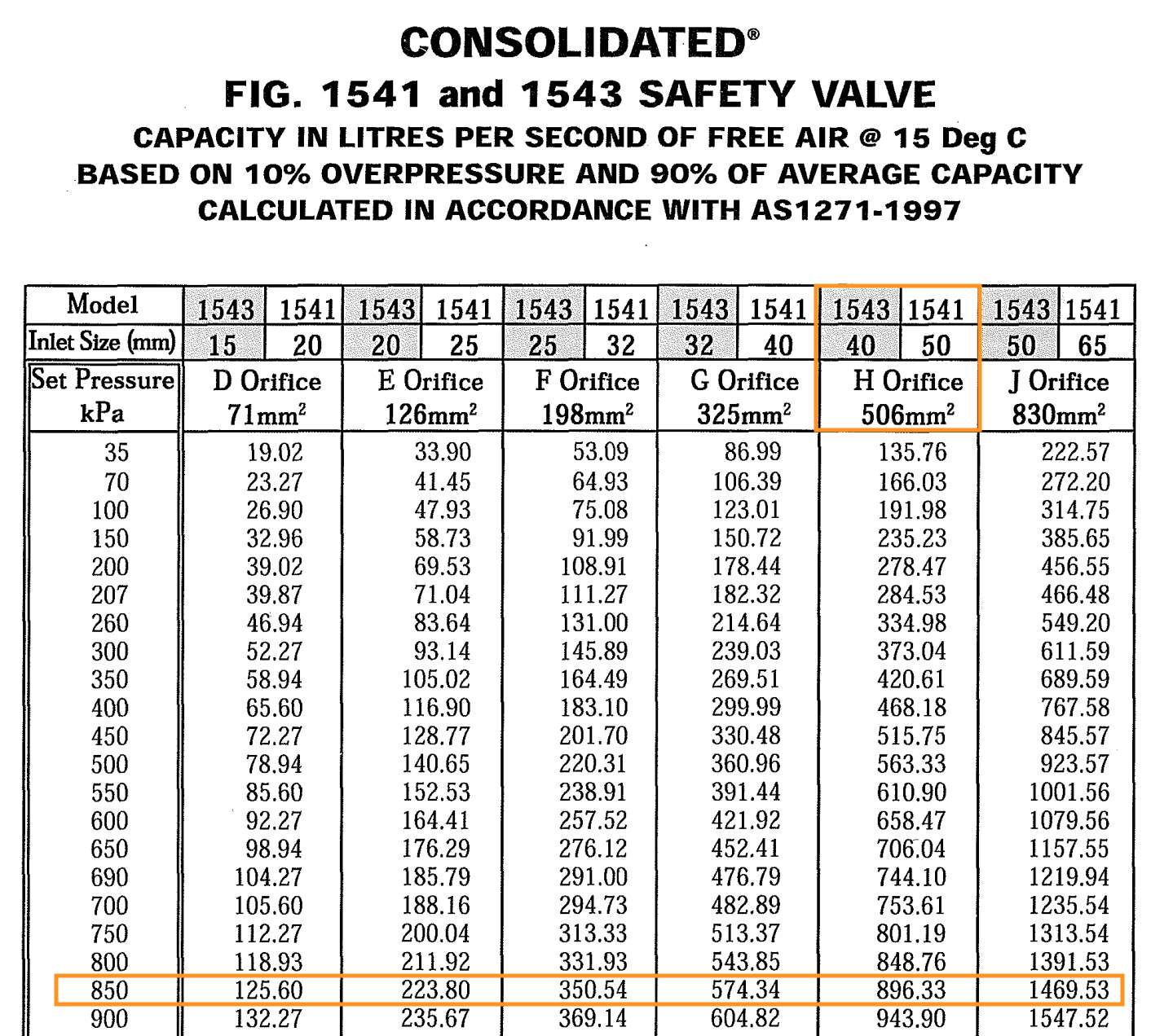
According to the set pressure of 861.844662 kPa, there will be specifically chosen in the safety valve catalogue. The range of set pressure is between 850 kPa and 900 kPa, which is 861.844662 kPa, however they share different amounts of flow rate specifically. By doing the interpolation, it can be accurately obtained for the flow rate of set pressure 861.844662 kPa. The safety valve chosen is the H orifice with 506 mm2 area and 40 mm inlet.
900 kPa-850 kPa943.90Ls-896.33Ls=861.844662-850V̇-896.33Ls
Volume flow rate at 861.844662 kPa is = 907.599011 L/sec
The first reason to choose the H orifice in this first part of question 5 is that it has the volume flow rate interpolation exactly at 861.844662 kPa of 907.599011 L/sec, and thus it accommodates more than enough to the free air delivery of ER7 compressor of 675 L/sec.
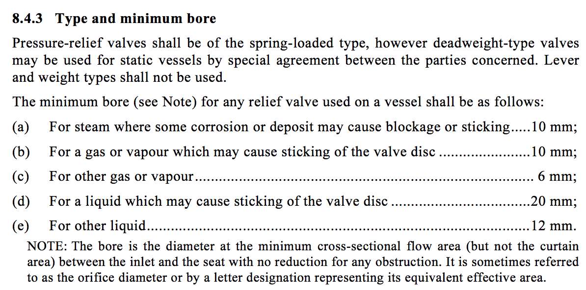
Secondly, H orifice has a discharge area of 506 mm2 that is also the reason to have it because, according to clause 8.4.3(a) from the standard that for the gas may result in blocking or sticking, and it should be bigger than 10 mm.
To calculate the diameter from the discharge area of 506 mm2 is:
Area=506 mm2=π.D24
∴D=25.38226 mm>10mm
The diameter of the discharge is much bigger than 10 mm that is also reasonably acceptable. (See appendix for valve specification).

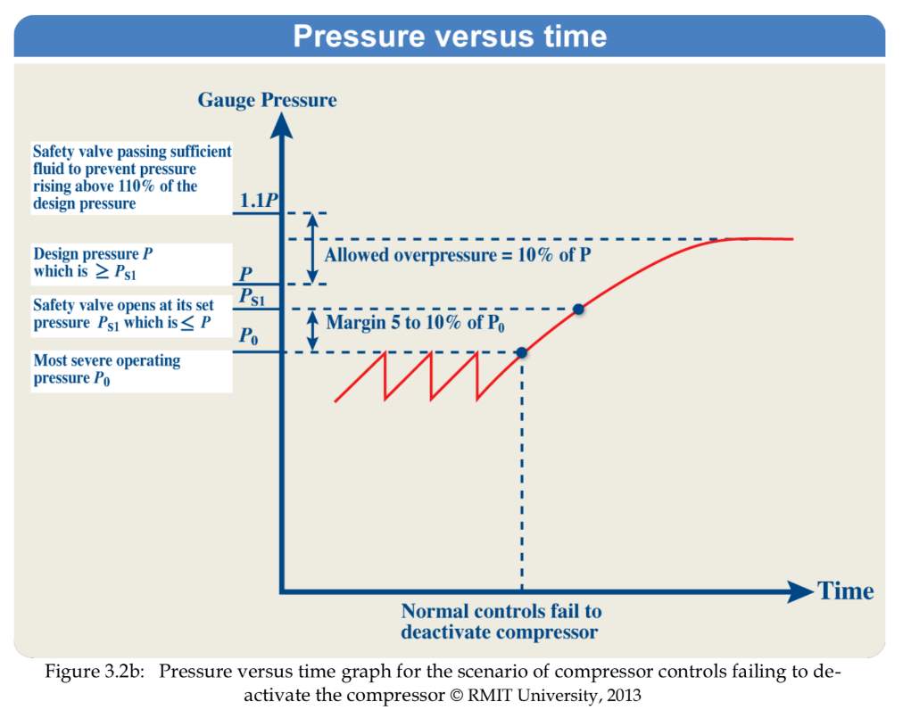
Figure 5
On the other hand, to conclude that at 790 kPa is where the valve starts to open, then going up to 861.844662 kPa where the valve is fully open. Also, the volume rate of 907.559 L/sec is big enough to accommodate free air delivery from air compressor ER7 of 675 L/sec. With more acceptable reason to choose H orifice is that, the bore diameter is well enough bigger than 10 mm.
Mild Fire Situation
It is assumed that this 2nd safety valve will only operate in the situation of a mild fire. The mild fire situation is that of which the pressure vessel goes beyond its design original design pressure due to the heat of the mild fire. The 2nd safety valve is to assist the first safety valve in releasing the pressure at the same time as the first safety valve. It is set at a higher design pressure, in the situation that the safety valve one is unable to cope with the heightened pressure.
This situation of mild fire is to get the discharge rate in kg/sec of the pressure relief device valve. By using the formula from the clauses 8.6.2.4(2) to get the mass flow rate of
ṁ=mYṗ+ṁp
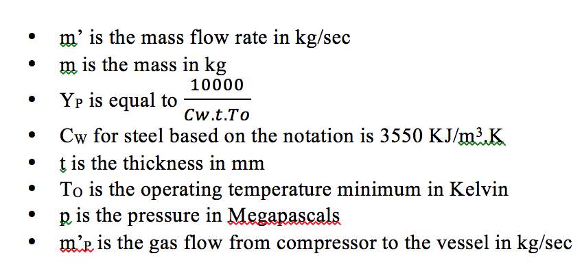
Figure 6
Simplified notation 8.6.2.4(b)
Calculating each of the element:
YP =
100003550KJm3K x 11mm x 285 K =8.985331 x 10⁻⁴ seconds-1
Yp is the relieving constant of the 2nd pressure vessel.
The groups choice is 11mm for the pressure relief device.
The choice of thickness of the pressure relief device is between 8 to 14mm is done, from an engineering viewpoint to minimize the cost of the project. Whilst, also understanding the importance of the support it gives the safety valve. The chosen thickness of 11 mm is the midway point of both these values. It will reduce the cost of the safety valve, whilst also maintaining a decent amount of thickness to prevent its rupture.
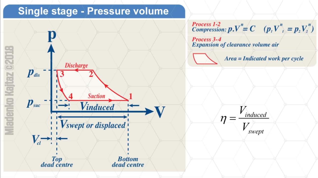
Overpressure during mild fire is 1.21 times the pressure design of 861.845 kPa which results in = 1.21 x 861.845 kPa = 1042.83245 kPa. This is based on the clauses of 8.2.2 that the pressure relief device can hold up the avoiding pressure more than 121% from the set vessel pressure design and the image from the lecture notes as follow. Finally, the amount of m’ can be calculated for YP
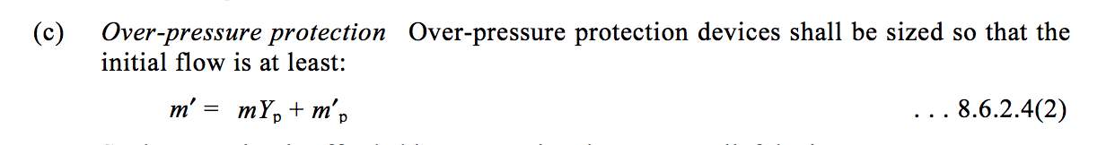
Figure 7
Clause 8.6.2.4(2)

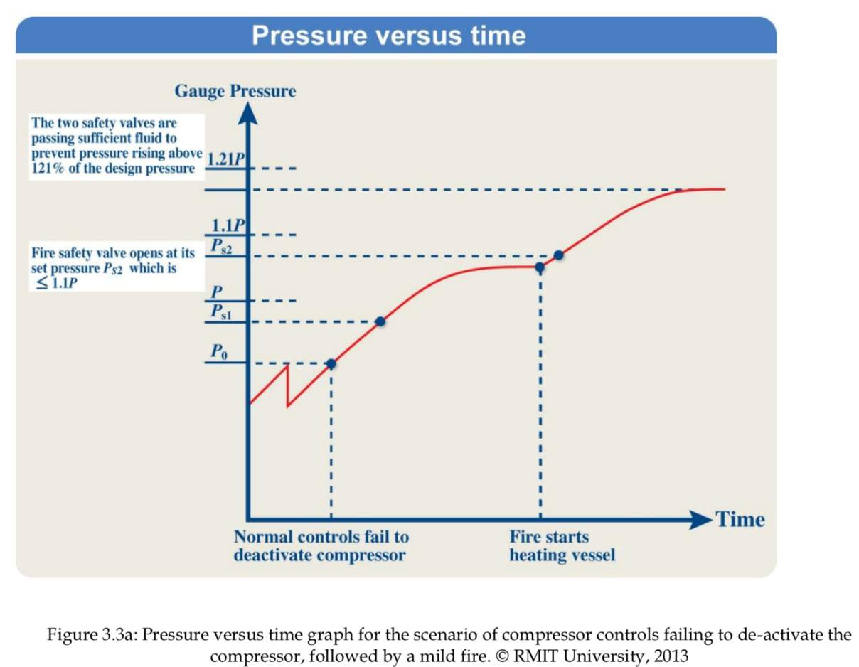
Figure 6
The condition here is that the volume stays constant; therefore Charles & Boyle’s law is applied as the ideal gas law.
m=P x VRRRT
m=948.0290875+101.3 x 14.164968 m3287 x 285=181.719089 kg
Due to that it is assumed that safety valve 1 is still operational and is accommodating for the free air delivery of the compressor. The calculations of mp the gas flow rate of the compressoris done with a volume flowrate of 0 L/s.
mP= Patmx V̇RṪ
mṖ= 101.3 kPa x 0L/s287 Jkg.K x 285 K̇
mṖ=0L/sec
Plug into the formula of
ṁ=mYṗ+ṁpbecomes
m’= 181.719089 kg x 8.95331 x 10-4 sec-1+0=0.162699kgsec
Also, in this part of b(i) it requires to calculate the minimum discharge capacity for the relief device in total:
By using the formula from clause 8.6.2.3(2)
Qa=41.44* mc*Tr*ZṀ12
Where,
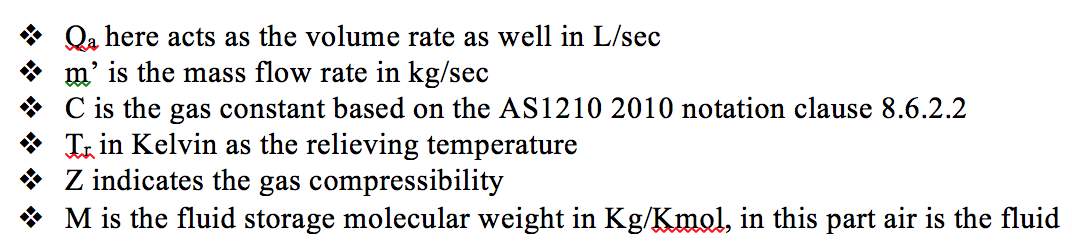
Figure 8
Simplified notation 8.6.2.2
By having all the values above, it can be inserted into the formula from clause 8.6.2.3(2) above.
Firstly, calculating C (Gas constant), where k is 1.4 for air constant
C=3.948k2k+1k+1/k-112
C=3.9481.421.4+11.4+1/1.4-112
C = 2.70332
Recollecting that this is a condition of constant volume therefore, Charles’ law for ideal gas law is applied, then obtain Tr is:
PsTO
=
P121%Tr
Ps as the set pressure chosen for the valve
P121% is the overpressure
948.0290875 kPa+101.3 kPa285 K
=
(1042.83245 + 101.3) kPa Tr
Tr = 310.748794 K
For the molecular weight for air M is 28.97 g/mol or 28.97 Kg/Kmol
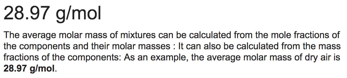
Figure 9
Molar mass of dry air
https://en.wikipedia.org/wiki/Molar_mass
Gas compressibility at this relieving condition or Z is 1
Qa=
41.44
m’C[
TrZM] ½
Qa=41.44*0.1626992.70332*310.748794*128.97(1/2)
Qa = 8.168399 m3/min
Qa = 136.139983 L/sec
For mild fire situation, another new second valve will be chosen is the E orifice. It is different compare to the first valve, because the Qa here is smaller as well. Also, to give a proof is to conduct another interpolation:
950 kPa-900 kPa247.55Ls-235.67Ls=948.0290875-900V̇-235.67Ls
V̇=247.081711 L/s
The volume rate, which has the design set pressure of 948.0290875 kPa in the second valve is = 247.081711 L/sec main reason that it is more than enough to fit the Qa in this mild fire situation.
Also, the diameter of the discharge area is:
Area=126 mm2=π.D24
∴D=12.66602 mm>10mm
Thus, the diameter even bigger than 10 mm according to clause 8.4.3(a), therefore it is acceptable. However, if to choose orifice D, it fits still the volume flow rate, but the diameter of the discharge will not reach 10 mm, it is lower than 10 mm. Therefore, E orifice is for the mild fire situation with 126 mm2 area and 20 mm inlet size still bigger than 10 mm.
Severe Fire Circumstance
It is assumed that this 3rd safety valve will only operate in the situation of a wild fire. This temperature relief valve will operate, if the heat of the flames in a wild fire situation reach the specific design temperature of 100 oC or 373 K. That is due to the heat of the flames in a wild fire, the first and second safety valves do not function properly and doesn’t open at their set design pressures.
After doing the mild fire situation, now moving on to even worse scenario of severe fire condition. Thus, the strength of the vessel is decreasing due to excessive amount of heat produced by the fire. To come up with this situation, using clause 8.6.2.4(b) to take action such an emergency situation.
Referring to clause 8.6.2.4(b) to formulate the mass rate (kg/sec)
ṁ=mYṫ+ṁp
This equation is slightly identical to 8.6.2.4(2) clause equation. To begin with, Yt here needs to be enumerated as:
Yt =
110000Cw.t.Tr
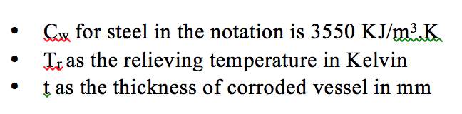
Figure 10
Notation from 8.6.2.2
Unlike, in the 2nd scenario, due to that it is assumed that safety valve 1 and 2 are not operational and cannot accommodate for the free air delivery of the compressor. The calculations of mp the gas flow rate of the compressoris done with a volume flowrate of 675 L/s.
Calculating
mP= Patmx V̇RTends up as:
In this worst fire situation, the
ṁp is regarded
mP= Patmx V̇RṪ
mṖ= 101.3 kPa x 675 L/s287 Jkg.K x 285 K̇
mṖ=0.835962 kg/sec
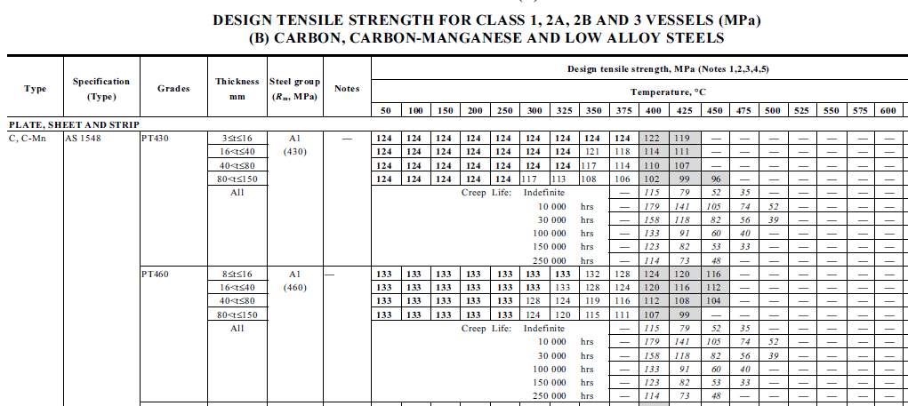
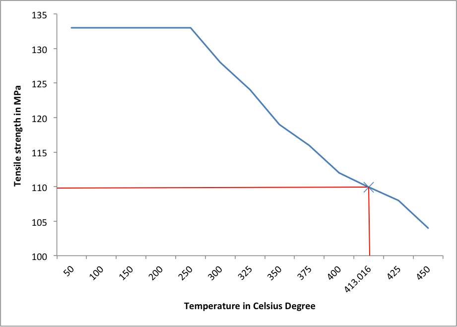
Next is to calculate the Tr as the relieving temperature in Kelvin. To guide this, it is to point out table B1(B) in Australian Standard to look at the specification of AS1548 PT 460 NR (L0) grade of low carbon manganese material with flanges range of thickness between 35 mm to 45 mm. This also indicates to assess the tensile strength by using formulae with all of the information completely from the notation in AS1210.
Tensile strength of Tr=Z1.21 x f
For the tensile strength in material C-Mn, therefore the value of TS at Tr with temperature of 100 C is 133 MPa, which is the value of f. By inserting 133 Mpa to the formula above will derive a result of (See Appendix E for the tensile strength):
- Value of Z is 1, as the gas compressibility
- TS is the tensile strength in MPa
Tensile strength of Tr=Z1.21 x 133 MPa=109.91375 MPa
Based on table B1(B) in AS1210 PT460, the flange thickness chosen between 35 mm to 45 mm is 40 mm as it is a middle number between the range. Therefore, by interpolating the values from the table will become:
425-400108-112
=
425-Tr108-109.91375
Tr = 413.01653 C = 686.01653 Kelvin
Hence, by having done calculating Tr in Kelvin, Yt can be computed just like the formula below:
Yt=1100003550KJK. m3 x 11 mm x 686.01653 K
= 4.106171 x 10⁻³ second-1
The mass flow rate as follow based on clause 8.6.2.4(1)
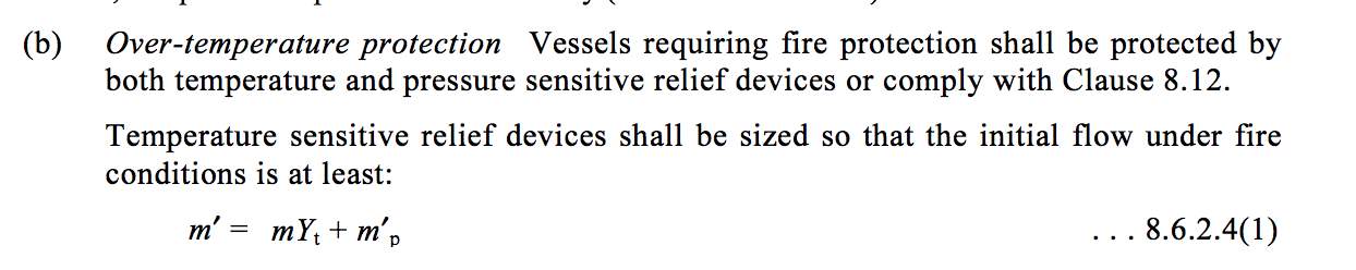
Figure 11
m’= mY
t + m’P
m’=181.719089 x 4.106171 x 10-3+0.835962=1.582132 kg/sec
The Qa for this severe fire situation would be:
Qa=41.441.5821322.70332686.01653 x 128.9712=118.021m3min or 1967.777318Lsec
With the reference temperature of 686.01653 Kelvin the volume flowrate results in being
1967.777318 L/s.
Wild fire condition shows that the Qa is pretty big, in fact that the relief device may not adequate to protect the receiver tank. However, to overcome this dire situation, it is preferably recommended to the workshop or company owner to alternate this issue by installing a fusible plug to cope against the wild fire situation. Fusible plug is able to shut automatically off in case there is worst flame condition and high heat occurs. According to clause 8.11 from AS1210, it is said as below. Therefore, it is best to implement a fusible plug.
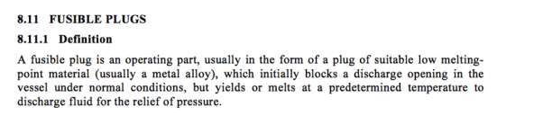
Figure 12
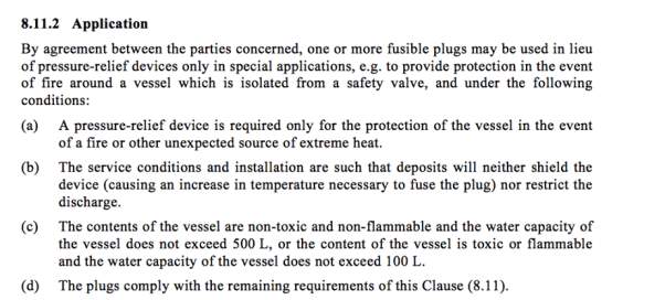
Figure 13
References
Kajtaz, M 2018, Lecture week 2: Considerations of Load Profile Storage and Load Factor (Revision) Receiver + Compressor, lecture notes, MIET1068 Mechanical Design 2, RMIT University
Y.C.V, Rao 2004, An Introduction to Thermodynamics, University Press, India
Standards Australian 1210 (2018), Pressure Vessel, AS1210-2010, Retrieved from Australian Standards Online
Hellemans, M 2009, The Safety Relieve Valve Handbook: Design and Use of Process Safety Valves to ASME and International Codes and Standards, Elsevier, USA
Appendices
Appendix A

Appendix A.1. (Lecture week 2)
Appendix A.2. (Lecture week 3)

Appendix B
Appendix C
Appendix D
Appendix E
Appendix F
Appendix G
Appendix H
- Starting at 690 kPa as the initial state of the receiver
- This calculation is of the first 90 seconds when the compressor is on at peak time.
101.3 kPa (675L/s – 750.0045L/s)(90 seconds) = (P2 – 690 kPa)(14164.496807)
P2 = 641.723239 kPa
- Due to the receiver exceeding 790 kPa as specific maximum pressure within the off peak time, the compressor cease to pump. Therefore, the time where receiver will reach 790 kPa is required to be calculated.
101.3 kPa (675L/s – 590L/s)(t) = (790 – 641.723239 kPa)(14164.496807)
t = 244.643647 seconds
- Moreover, at this stage the compressor resumes to pump the pressure fails at this level of 690 kPa
101.3 kPa (0 – 590L/s)(t) = (690 kPa – 790 kPa)(14164.496807)
t = 23.699528 seconds
Remainder = 1.656 seconds
- 101.3 kPa (675L/s – 590L/s)(1.656 seconds) = (P2 – 690 kPa)(14164.496807)
P2 = 691.007171 kPa
- 101.3 kPa (675L/s – 750.0045L/s)(90 seconds) = (P2 – 691.007171 kPa)(14164.496807)
P2 = 642.727428 kPa
- 101.3 kPa (675L/s – 590L/s)(t) = (790 – 642.727428 kPa)(14164.496807)
t =242.267217 seconds
- 101.3 kPa (0 – 590L/s)(t) = (690 kPa – 790 kPa)(14164.496807)
t =23.699528 seconds
Remainder = 4.03816 seconds
- 101.3 kPa (675L/s – 590L/s)(4.03816) = (P2 – 690 kPa)(14164.496807)
P2 = 692.454770 kPa
- 101.3 kPa (675L/s – 750.0045 L/s)(90 seconds) = (P2 – 692.454770 kPa)(14164.496807)
P2 = 644.178009 kPa
- 101.3 kPa (675L/s – 590L/s)(t) = (790 – 644.178009 kPa)(14164.496807)
t = 239.880974 seconds
- 101.3 kPa (0 – 590L/s)(t) = (690 kPa – 790 kPa)(14164.496807)
t =23.699528 seconds
Remainder = 6.419498 seconds
- 101.3 kPa (675L/s – 590L/s)(6.419498 seconds) = (P2 – 690 kPa)(14164.496807)
P2 = 693.902368 kPa
- 101.3 kPa (675L/s – 750.0045 L/s)(90 seconds) = (P2 – 693.902368 kPa)(14164.496807)
P2 = 645.625067 kPa
- 101.3 kPa (675L/s – 590L/s)(t) = (790 – 645.625067 kPa)(14164.496807)
t = 237.499637 seconds
- 101.3 kPa (0 – 590L/s)(t) = (690 kPa – 790 kPa)(14164.496807)
t = 23.699528 seconds
Remainder = 8.800834 seconds
- 101.3 kPa (675L/s – 590L/s)(8.800834 seconds) = (P2 – 690 kPa)(14164.496807)
P2 = 695.349967 kPa
- 101.3 kPa (675L/s – 750.0045 L/s)(90 seconds) = (P2 – 695.349967 kPa)(14164.496807)
P2 = 647.073206 kPa
- 101.3 kPa (675L/s – 590L/s)(t) = (790 – 647.073206 kPa)(14164.496807)
t = 235.118299 seconds
- 101.3 kPa (0 – 590L/s)(t) = (690 kPa – 790 kPa)(14164.496807)
t = 23.699528 seconds
Remainder = 11.182173 seconds
- 101.3 kPa (675L/s – 590L/s)(11.182173 seconds) = (P2 – 690 kPa)(14164.496807)
P2 = 696.797566 kPa
Cite This Work
To export a reference to this article please select a referencing stye below:
Related Services
View all


Related Content
All TagsContent relating to: "Engineering"
Engineering is the application of scientific principles and mathematics to designing and building of structures, such as bridges or buildings, roads, machines etc. and includes a range of specialised fields.
Related Articles

DMCA / Removal Request
If you are the original writer of this dissertation and no longer wish to have your work published on the UKDiss.com website then please: