Building Information Modelling for the Make Liverpool Project
Info: 15369 words (61 pages) Dissertation
Published: 11th Dec 2019
The use of BIM could significantly improve the successful commercial delivery of the Make Liverpool project.
CONTENTS
2.2.1 Plain Language Questions (PLQ)
2.1.2 Employers information Requirements (EIR)
2.1.2 Master Information Delivery Plan (MIDP) & Task Information Delivery Plan (TIDP)
2.2.1 Organisational Information Requirements (OIR)
2.6 Government Soft Landings (GSL)
2.7 Digital Plan of Work (DPOW)
GLOSSARY OF TERMS
| BEP | BIM Execution Plan |
| BIM | Building Information Modelling |
| CAD | Computer-Aided Design |
| CAPEX | Capital Expenditure |
| CIC | Construction industry Council |
| COBie | Construction Operations Building information exchange |
| DPOW | Digital Plan of Work |
| EIR | Employers Information Requirements |
| FM | Facilitates Management |
| GSL | Government Soft Landings |
| IFC | Industry Foundation Classes |
| ISO | International Organisation for Standardisation |
| LJMU | Liverpool John Moores University |
| MIDP | Master Information Delivery Plan |
| NBS | National Building Specification |
| NEC3 | New Engineering Contract 3 |
| NRM1 | New Rules of Measurement 1 |
| OPEX | Operational Expenditure |
| PAS | Publicly Available Specification |
| PIP | Project Implementation Plan |
| PLQ | Plain Language Question |
| RICS | Royal Institute of Chartered Surveyors |
| ROI | Return on Investment |
| TIDP | Task Information Delivery Plan |
1.0 WHAT IS BIM?
The use of BIM in the construction industry has transformed the way projects are designed, built and maintained across their life cycle. BIM utilises advanced digital software and tools in order to create 3D models of building infrastructure, this system allows large quantities of information concerning the design, operation and maintenance to be stored and shared across a number of professions.
This collaboration allows designers, clients and users to contribute to the design ensuring the best possible outcome is achieved and each respective individual is satisfied before the construction stage commences. Simulation enables the identification of any flaws within the design in the early stages, and is essential to the certainty of any specified time, cost and quality parameters.
The BIM Mandate of April 2016 requires that all centrally procured UK Government projects are to be at BIM Level 2, coinciding with the aims of the construction 2025 strategy; which seek to lowers costs, faster delivery, lower emissions and improve exports (NBS, 2016).
According to UK government BIM has significantly contributed to the savings of £2.2billion in construction costs between the years 2013 and 2015. BIM is a continuously developing programme as shown in Figure 1, each stage seeks to improve upon the last in terms of its holistic approach to the industry and seeks to implement:
- more technological innovations
- greater efficiency
- lower costs
- increase in end value
- increasing sustainability
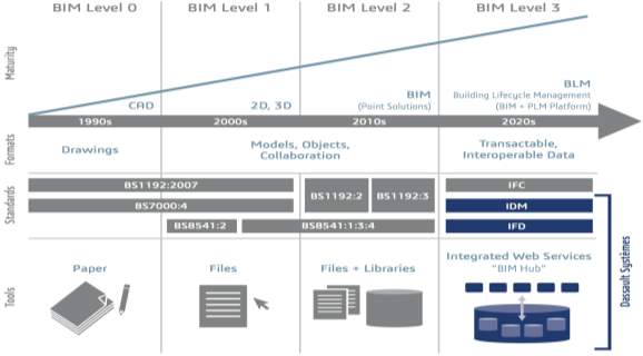
Figure 1: Building Information Modelling (BIM) Maturity Model.
A clearly defined strategy is key to the successful implementation of BIM (NBS, 2016), where people and information can work together effectively and efficiently through defined processes and technology (RICS, 2014).
A BIM Strategy is underpinned by a comprehensive understanding of BIM maturity levels (Figure 2). It is for Make Liverpool as the Client to consider if project delivery could be improved through the adoption of a BIM approach (NBS, 2016). For example, BIM could be utilised at the feasibility stage by modelling a number of scenarios in relation to construction methods, and could simulate the effect of these different methods in terms of time, cost and quality throughout the life cycle of the building. Once the maintenance and operational phase of the building has commenced, BIM would also support the alignment of end user requirements and efficient facilities management of the building at concept stage.
| BIM Maturity Levels | Description |
| Level 0 | 2D CAD drafting with paper the most likely data exchange method. |
| Level 1 | Managed 2D or 3D CAD drafting with a collaboration tool to provide a common data environment. |
| Level 2 | A managed 3D environment includes data produced independently by all members of the design team. |
| Level 3 | A fully integrated and collaborative process using web services, where all discipline feed into one single model. |
Figure 2. BIM Maturity Levels (Herbert Smith Freehills LLP, 2016)
There is potential for the Make Liverpool project to utilise Level 2 BIM. This rationale is underpinned by the potential efficiency gains, which can be achieved during both the CAPEX and OPEX stages of the building life cycle, combined with the achievement of maximum user satisfaction. The process utilises 3D modelling, increased collaborative working and rapid decision-making.
There are many potential benefits of implementing BIM Level 2. The decision by the Client to implement BIM Level 2 should directly relate to the expected benefits in regards to CAPEX vs OPEX costs and ROI (NBS, 2016)
1.1 THE BIM PROCESS
The Government 2011 Construction Strategy (GCS) required that all centrally procured Government projects must be utilising BIM Level 2 by 2016 (NBS, 2017).
In conjunction with the UK Government, the BIM Task Group have developed eight pillars of BIM which should be incorporated into any construction project aiming to achieve BIM Level 2 (Herbert Smith Freehills LLP, 2016):
- Employers Information Requirements
- BIM Execution Plan
- RIBA Digital Plan of Works
- Collaborative Production of Information
- CIC BIM Protocol
- Government Soft Landings
- Classifications
- Security
2.0 BIM LEVEL 2
2.1 PAS 1192-2:2013
PAS 1192-2 underpins the information management for the both the capital and delivery phases of a project. This specification provides a framework for a BIM project including the requirements for EIR and the BEP (ibid). The EIR and BEP fundamental principles for BIM Level 2 information management include; plain language question (PLQ), a Project Implementation Plan (PIP), Master and Task Information Delivery Plan (M&TIDP), Task Information Delivery Plan (TIDP), project delivery team roles, responsibilities and authority (BSI, 2013).
PAS 1192-2 focuses specifically on project delivery, where the majority of graphical data, non-graphical data and documents, known collectively as the project information model (PIM), are accumulated from design and construction activities.
As part of the execution of the Design BIM Management Plan and in order for the project to be completed successfully, the Design Team will assign an individual to the role of Design Team BIM Manager. The individual must have sufficient BIM experience for the size and complexity of the project and have relevant proficiency in the proposed BIM authoring and coordination software. The individual shall also serve as the main point of contact with the Design Team for BIM related issues.
PAS1192-2 is fundamental to successful BIM implementation, and consequently changes to this element of BIM must be made if the construction industry is to progress to Level 3 BIM adoption in the future. Pas1192-2 was introduced in February 2013 with the intention to facilitate the adoption of BIM level 2 in construction projects. Pas1192-2 builds on BS1992 which covers the collaboration of architectural engineering and construction information. With the terms and definitions section pas1192-2 brings to life the information management and giving light to the information management process. There is also the intention to bring in another document which couples with pas1192-2, aiding its functionality and helping BIM move from level 2 to level 3. Pas1192-3 will offer guidance on the use of asset information model. And provide assistance on best practices within portfolio management. Pas in itself is not an actual contract but does provide standards which can be incorporated into all other projects.
2.2.1 Plain Language Questions (PLQ)
The British Standards Institute defines Plain Language Questions (PLQs) as:
“Questions asked of the supply chain by the employer to inform decision-making at key stages of an asset life cycle or project from PAS 1992-3.” (BSI, )
It is crucial that Clients receive information on a transparent basis so that it can inform the decision making process at every stage of the building lifecycle. PLQs represent a minimum requirement for the exchange of information throughout a construction project.
The development of a Project Information Model is fundamental to BIM and includes every piece of information required to design and construct a built asset. PAS 1192-2 provides a structured method for the capture of project information through the information delivery cycle (IDC). The IDC contains Employer’s Decision Points – key points at each project stage where the employer requires specific information to inform their decision making.
PLQs are formulated by the Client/Employer and should be kept simple to ensure that the delivery team provides the right information in the right format to support the Decision Points.
Typical PLQs include:
- How will the facility be run?
- Can the project be delivered on time?
- Is the Cost Plan robust?
The answers to PLQs should always be supported by sufficiently detailed information to validate the responses (Gleeds, 2014).
2.1.2 Employers information Requirements (EIR)
PAS 1192-2 provides guidance for the use of Employers Information Requirements (EIR). The EIR is one of the most important BIM documents, and is created at the start of the project by the client to set out their strategic objectives for the use of BIM. It helps the suppliers and the client understand ‘why’ they want to use BIM on a given project and ‘what’ they want BIM to deliver (The B1M, 2015) as well as ‘how’ the information should be delivered.
It is defined as a “pre-tender document setting out the information to be delivered, and the standards and processes to be adopted by the supplier” (BSI, 2013) and forms part of the appointment and tender documents used to appoint a contractor and design team.
At BIM Level 2, the use of the EIR is outlined by PAS1192-2:2013 as illustrated by the Information Delivery Cycle contained within that standard:
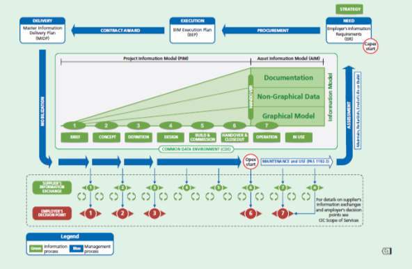
Figure 3 – The Information Delivery Cycle (BSI, 2013)
The EIR defines the models which are required at each stage of the project including their level of detail or definition (LoD). As shown in the Information Delivery Cycle in Figure 3 the “model” (Project Information Model or PIM) consists of a graphical model, non-graphical data and documentation. As the project progresses through its life cycle, the volume and detail of information in the model increases as the building progresses to completion and the parties to the project build up more information.
The information required throughout the project lifecycle through initiation, design, construction, operation and demolition and contained within the model is defined by the EIR and is split into three sections (BIM taskgroup, 2013):
TECHNICAL
|
MANAGEMENT
|
COMMERCIAL
|
Once the asset has been completed, the PIM is converted into an Asset Information Model (AIM) and although Figure 3 depicts the information in the model remaining the same, in practice, as changes are made to the building or as Facilities Managers accumulate more data, the size or make-up of the AIM may change throughout the operational life of the asset.
As outlined in PAS1192-3:2014 and as described by Ashworth, Druhman and Tucker (2016), the EIR is developed from the following key documents as show in Figure 4:
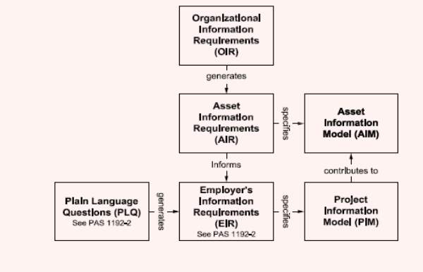 Figure 4 – Content inputs and outputs of the EIR
The Organisational Information Requirements (OIR) underpin the creation of the Asset Information Requirements (AIR) which are defined as “the data and information requirements of the organisation in relation to their assets” (BSI, 2014). The AIR, together with the relevant questions from the Plain Language Questions (PLQ) help the Client to interpret what information is required for the EIR. The EIR is then used as a tender document which suppliers respond to with the BIM Execution Plan (BEP) which explains “how the information modelling aspects of a project will be carried out” (BSI, 2013, p.3) or how they will satisfy the client requirements as set out in the EIR.
A further benefit derived from the EIR is that it allows a clear understanding of the design, specification and construction programme allowing clients to better assess construction effort and associated costs. It achieves this by ensuring that not only is the information available, but that it is structured appropriately such that it can be retrieved; an accurate and timely cost plan needs all the objects in the model together with costs attached as they are being added to the model, for example (BIFM, 2017).
A further significant benefit relates to the operational phase of the project through the early involvement of key suppliers. Research suggests that the operational phase equates to 60% of the entire costs of a project (Akcamete et al cited by Ashworth et al, 2016a) and of the operational costs, 80% “can be influenced in the first 20% of the design process” (ISO, cited by Ashworth et al. 2016a). Moreover the MacLeamy curve (Figure 6) confirms that the more effort put in at the early stages of a project the lower the costs in making design changes and that doing so has a direct correlation with delays, wastage and delivery costs.
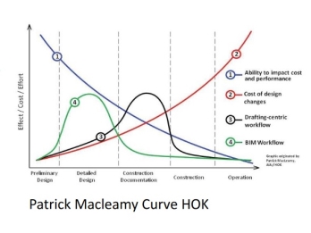
Figure 5 – The MacLeamy Curve (adapted from NBS, 2011)
The EIR produced pre-tender stage helps project stakeholders to understand what the objectives for the use of BIM are. Consequently, a well written EIR can facilitate the early involvement of Facilities Managers so that operational requirements can be incorporated into the design. This could therefore have significant impact upon the potential for cost savings throughout the design and operational phase.
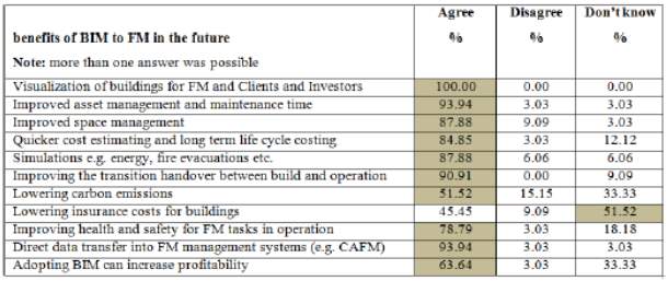 Some additional benefits, in the context of BIM adoption from a Facilities Manager’s perspective are summarised in Figure 6 (Ashworth, Druhman and Tucker, 2016):
Figure 6 – Perceived benefits of BIM to Facilities Managers in the UK
EIRs provide suppliers with a clear picture of the scope of works so a well written EIR prevents wasted effort (and associated costs) in suppliers generating data that is of no value or is not required by the client. Conversely, if the client receives the information that they expect then there will be fewer requests for information (RFIs) and change orders. This is a benefit for both suppliers and clients and is listed alongside other recognised benefits of BIM Level 2 below (Barlish and Sullivan, cited by Dowsett and Harty, 2015):
- Improved quality control;
- On-time completion;
- Reduced waste through reduction in re-work from early coordination;
- Improved scheduling;
- Early clash detection;
- Productivity improvements;
- Increased opportunities for pre-fabrication;
- Fewer requests for information (RFI);
- Fewer change order;
- Early design error detection;
- Less skilled workforce required reducing costs;
- Improved safety performance through construction simulation;
- Interoperability – technically, culturally and organisationally
That being said, there are a number of important ways in which the benefits of BIM Level 2 are not fully realised, some of which, it could be argued, have their roots in the production of the EIR.
A report by McGraw Hill Construction, cited by Ashworth et al (2016a, p. 2) identifies that “three quarters of all contractors surveyed report a positive ROI on their investment in BIM” but that the ultimate beneficiaries are clients because benefits accrue throughout the lifecycle. However, it is suggested, templates such as the EIR are not focussed on clients’ needs; a problem which is compounded by insufficient client knowledge and experience. Rodriguez-Trejo et al (2017) find that the EIR template defines categories but lacks an analytical approach to justifying decisions which may have a large impact on costs later in the life cycle.
These findings are reinforced in Construction Manager Magazine (2017) which identifies a lack of client knowledge in terms of what they are asking for from BIM and the perception that BIM is a cost that delivers uncertain return on investment. It is further suggested that a large part of the problem of unclear benefits is the one-off nature of projects or the life-cycle phase of the project in which the benefits were measured, reducing the generalisability of the data. This is due to the relatively early stage of industry adoption of BIM and a current lack of comparable projects in which BIM was used consistently and by all suppliers throughout the lifecycle (Ibid.). Clearly, the issue of client knowledge can again be linked to the production of an EIR which is not fit for purpose.
Reasons for difficulties in production of the EIR are varied and are dependent on a number of factors. Al Ahbabi and Alshawi (2015) identify that a successful EIR relies upon the Client’s capability and maturity; the maturity of supply chain; available technology platforms; and the type and complexity of the project. The more complex the EIR, the higher the risk of it not meeting its requirements in terms of time, quality and cost. This may be attributed to the lack of necessary experience of some Clients in the creation of an effective EIR (The B1M, 2015b). Furthermore the client organisation may not have a clear asset management strategy which in turn makes the OIR and IAR difficult to define and result in a poor quality EIR (Ashworth, Druhmann and Tucker, 2016).
2.1.2 Master Information Delivery Plan (MIDP) & Task Information Delivery Plan (TIDP)
The MIDP is the project’s primary plan for how information is to be prepared, by who and which protocols and procedures should be used, incorporating all of the relevant task information delivery plans. (PAS 1192-2013)
The MIDP is compiled after the contract has been awarded. The contractor or supplier should submit a post contract BIM execution plan confirming and developing the Project Information Plan (PIP) in order to create the Master Information Delivery Plan (MIDP). (Designing Buildings, 2017)
After the contract has been awarded the project delivery manager (PDM) initiates confirmation of the resource availability and the capability, identifies training and education needs and develops the MIDP. The PDM then uses the completed MIDP to manage information delivery onsite and the information deliverables.
The information required by PAS 1192:2013 includes;
- Models
- Drawings
- Specifications
- Equipment
- Schedules
- Equipment
- Room data sheets
- Change control
The MDIP is developed by the completion of a series of Task Information Delivery Plans (TIDP) that are developed by individual task team managers and sets out the responsibility for each specific information requirement. The MDIP then collates this information and aligns them with the design and construction programmes.
The TIDP is a list of deliverables separated into individual tasks and includes details such as format, date and responsibility. Milestones must be aligned along with the design and construction programme.
The TIDP must also show how responsibility for the prepared documents transfers between team members and must also take account of the required sequence of model preparation for any work packages used within the project. (PAS 1192:2013)
As well as the TIDP, a Responsibility Matrix is used to create the working MIDP document. The matrix sets out the relationship between each of the disciplines and the production of information or models. After the MIDP is completed this feeds into the BIM Execution Plan (BEP) document and thereby concludes the data for information management of the project. (Kumar, 2015).
In order for BIM Level 2 to realise its full potential the information flows between project team members must be increased that that of a traditional 2D environment. The roles and responsibilities of stakeholders differ from non BIM projects and therefore issues relating to model development, progression and quality must be managed in a different way throughout the entire project lifecycle.
While RICS state that the structured solution that the MIDP offers lays the foundations for successfully implementing BIM across the project lifecycle (RICS, 2015), Eastman et al (2008) conclude that as BIM requires the collection and representation of project information the benefits to product and process can only be achieved if information is shared correctly (Eastman et al, 2008).
By implementing high levels of communication between stakeholders achievements through BIM via a well-managed MIDP the benefits would include, ‘cost and time reduction, communication, coordination and quality improvement, negative risk reduction, scope clarification, organization improvement, fewer software issues, fewer returns for information, and lower design costs and contractor costs’ (Barlish and Sullivan, 2012; Bryde et al., 2013)
Demian and Walters (2013) concluded that “the BIM-based solution helped to foster more accurate, on-time and appropriate exchange of information between project participants.” This exchange of information can be achieved by implementing a successful information management system (MIDP) by the PDM.
Although the use of an MIDP and TIDP in practice seems like a matter of creating and managing a process, many organisations are reluctant to share information with other suppliers, stakeholders or the Client. Papadonikolaki et al. (2015) stated that, ‘the project teams apply BIM partially during design and do not share the information amongst all stakeholders.’
In order for BIM Level 2 to reach its potential the industry must get all parties involved in the project to ‘buy in’ to complying with the MIDP which may be challenging for the PDM to remove traditional views of information sharing.
It has also been found that although there are managerial benefits of BIM’s information flows, integrated operations and works space management, there are gaps at an inter-organisational level that are directly related to operational loss and explicit organisational structure. (Papadonikolaki et al. (2015)
This may create an issue for the PDM to give suppliers the motivation to comply with the MIDP, especially at this stage of BIM application. However, as the use of these BIM level 2 protocols increases, so too will the integration of BIM by suppliers as they transform their processes.
Whilst this transition is still occurring many organisations still have both BIM and non-BIM projects ongoing which can create an additional layer of complexity though the project delivery network. In some cases failed BIM projects have resulted in organisations shifting back to traditional practices due to failed implementations at organisational levels (RICS, 2015).
In order for this not to be the case the PDM must ensure that the MIDP and TIDP’s procedures and protocols are kept to by all suppliers, stakeholders and designers.
2.2 PAS 1192-3:2014
PAS 1192-3 is the specification for information management for the operational phase of the asset using BIM, acting as a partner to PAS 1192-2, PAS 1192-3 develops the process for the operational phase of the asset making it crucial to the operational phase of a building assets lifecycle i.e. asset, facilities and maintenance management, thus supporting the BIM Level 2 objective of PAS 1192-2. (Herbert Smith Freehills LLP, 2016).
PAS 1192-3 addresses the operational phase of a building asset regardless of whether it is a new or existing development. The key concept of PAS 1192-3 is where it was previously considered that the operational phase of an asset would start at the handover stage, it should now be considered much earlier within the design stage. Rather than facilitating project delivery, PAS 1192-3 provides ‘added-value’ to a built asset through the benefit of a better understanding the operational and maintenance needs of the building asset earlier within the design process i.e. plan of work stages 0-3.
As a result of this early engagement and lifecycle cost consideration, further benefits such as reduced running costs and improved energy performance can be achieved through the automated transfer of accurate data at both the handover and operational stage. Additionally, there is an increased awareness of both the operational and maintenance requirements of an asset at the design stage, resulting in improved decision making along with an improved quality of information through the transfer of digital data (AIM) to the FM team which may be used in the day to day running of the building asset (BSI, 2014).
However, a barrier to the success of this protocol is where the concept or even benefits of establishing a digital AIM is not fully understood by the employer and so the AIR and EIR do not specify the data required to produce a relevant and useful AIM (BIM Task Group, 2014).
2.2.1 Organisational Information Requirements (OIR)
The Organisation information requirements (OIR’s) form part of PAS1192-3 of which provides specifications for information management of the operational phase of assets using Building Information Modelling (BIM) PAS1192-3 (2014).
PAS1192-3 works in partnership with PAS1192-2 and cross-references with other standards such as BS ISO 55000 with OIR playing a crucial role in the design construction and operation of an asset, providing key up-to-date information, which can be easily accessed for use in the operational phase of an asset.
Although the requirements (OIR’s) are considered to begin at handover these prove to be extremely valuable in major works PAS1192-3 (2014). Once OIR needs have been identified and verified with the help of ISO 55000. PAS1192-3 is then used to manage the asset information, which gives FM teams an accurate up-to-date Asset Information Model (AIM) Harris (2014).
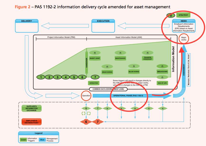
Figure 7 – PAS1192-3 (2014)
Figure 7 above shows that PAS1192-3 feeds directly into the Employers Information Requirements and is integral in the RIBA plan of work 0. PAS1192-3 and PAS1192-3 are cross-referenced and inform one another.
Harris (2014) confirms that by using BIM level 2, important organisational information can be gathered at the design stage and kept up-to-date as construction takes place helping FM’s to have quick and easy access to information. This is a vast improvement as historically FM’s would have to sift through large amounts of paperwork and manuals in order to find warranties etc. on assets, whereas now they can quickly access this information in an Asset information model (AIM) Harris (2014).
OIRs can be gathered at an early stage and included into the Project information model (PIM) and then transferred to AIM on completion, which facilitates a smooth project handover Harty et al (2015).
OIRs play a crucial role within PAS1192-2 and PAS1192-3 in identifying an organisation’s needs. If this information is managed by the organisations FM’s team then accuracy of data can be achieved. However, Harty et al (2015) notes that if a new contractor is brought in, retaining the accuracy of data during the transfer process from out-going contractor to client, then to in-coming contractor carries significant risk.
Harty et al (2015) and Harris (2014) discuss the process of data collection, validation and application that is required in PAS1192-3 as a ‘daunting’ task to smaller organisation and there is a view that companies can find themselves lost in paperwork which is ultimately time consuming and costly.
2.2.2 BIM Execution Plan
Post-contract, the successful contractor submits a further BIM Execution Plan confirming the supply chain’s capabilities and providing a Master Information Delivery Plan (MIDP). The MIDP is the primary plan setting out when project information is to be prepared, by whom, using what protocols and procedures; it is based on a series of individual Task Information Delivery Plans setting out responsibility for specific information tasks.
Within the PAS1192-2:2013 Annex A, a BIM Execution Plan is defined as a “plan prepared by the suppliers to explain how the information modelling aspects of a project will be carried out.”
A BEP is one of the fundamental principles for Level 2 BIM (PAS1192-2:2013 page ix) and comes in two forms: pre- and post-contract award. Pre-contract it intended to be used to help evaluate a company’s proposed approach. Post-contract it becomes a collaborative document explaining who is responsible for what and when.
A BEP should contain the following:
- A list of roles and responsibilities, and capability statements.
- Major BIM milestones or deliveries related to the programme.
- Standards and procedures that will be employed, including .how information will be approved
How collaborative information will be utilised
- how the models will be zoned and broken down for each discipline
- construction / modelling tolerances
- the location and orientation of all models
- file naming conventions
- layer naming conventions
- annotation standards
Case Study: National Graphene Institute (adapted from BIM plus, 2015)

Level 2 BIM was used on the project, employing a fully federated BIM model which was used to coordinate with the large amount of mechanical and electrical services the sub-contractor needed to install into what is a technically complex, highly serviced university research building.
Despite the use of a federated model, not all suppliers used a 3D graphical package; the architect produced 2D drawings which were converted to 3d by the main contractor.
Nevertheless, BIM proved its worth by enabling the complex M&E to be fitted in to a building volume that had BIM not been used, could have required a building double the size of the design produced. Clash detection was used intensively producing estimated cost savings of £100,000 including a single clash that would have cost £30,000 to rectify on site. Finally, the BIM model will continue to drive value for the client in operations and maintenance with a version of the model containing hyperlinks to manuals of some of the plant assets.
One potential shortcoming of PAS1192-2 is the reliance upon the quality of information inputted; incorrect information can have a big impact on the final outcome of a project. Having the correct information within BIM is a key component to a successful delivery. Inaccurate information could result in additional capital costs increasing by up to 25%. BIM also relies on all information being in a standardised form. This issue within BIM level 2 represents a significant barrier to progressing to Level 3 BIM.
In order for pas1192-2 to grow into level 3 it must be able to either convert all information into one single standard in order to be able to filter and use the information. Or set a single standard document which allows all different disciplines to use the one document. Being dependant on different sections converting their information to make it fit for the model should be an issue addressed within the model itself giving different sources the ability to input. This would massively improve any time issues and minimise any disputes.
Case Study: Skanska
An example of the barriers and benefits posed by BIM is identified by Jordan (2013) who offered an insight into issues Skanska’s FM team were facing during projects and how BIM impacted on these.
One key barrier was the lack of inclusion of the FM team in the design process to give an input into the OIR’s allowing for more accurate data as, pre-BIM they felt detached from the design team which could affect Capital Expenditure (CAPEX) and Operational Expenditure (OPEX). The Skanska team felt that this reduced the chances of assets being ‘FM friendly’ with the inability to operate or maintain assets due to design issues. The other issue raised by the Skanska team was that of insufficient information on hand-over i.e. incomplete information, missing information, and information of incorrect format.
Skanska identified 3 requirements that would allow BIM to be used by the business:
- Assemble its O & M contracts more efficiently;
- Improve its asset management; and
- Provide building performance information to help the designers ultimately improving sustainability.
Skanska undertook 2 projects to establish their FM requirements, implementing early involvement of their FM’s in the design process and found that this helped with the previously noted issued, but did say that they still need to refine their framework, as with the implementation of any new models there will be teething problems.
The EIR provides benefits for both clients and their suppliers. The principle benefit for the Client is the that it aids effective decision making at key stages aligned with the specified plan of works (RIBA or APM for example). If a client uses a Gateway Review process, a ‘data drop’ of elements of the PIM at the pre-determined Gateway point can help the client decide whether to proceed through the gate to the next phase of the project.
2.3 PAS 1192-4
BS 1192-4:2014, Collaborative production of information Part 4: Fulfilling employer’s information exchange requirements using COBie – Code of practice was published by the British Standards Institution (BSI) in September 2014. BS 1192-4 summaries the UK practice of COBie, (Construction Operations Building information exchange) a worldwide-agreed information exchange scheme for exchanging facility info among the supply chain and the employer. This particular code of practice outlines opportunities for the exchange of information during the lifecycle of a Facility (Herbert Smith Freehills LLP, 2016).
The COBie delivers a mutual structure for the exchange of information regards to existing and new Facilities, counting both infrastructure and buildings. The use of COBie makes sure that the info can be ready and used deprived of the need for knowledge of receiving and sending databases or applications. It makes sure that the knowledge exchange can be studied and authenticated for compliance, continuity and completeness (JCT 2016).
Design information is shared through a common file arrangement, which allows any organisation to be able to combine the data with their own and create central BIM model. It is therefore essential that the software used by stakeholders involved in BIM must be capable of transferring to one of the common file formats such as COBie (Construction Operations Building Information Exchange.
Advantages of the protocol include:
- Better planning and design: Using BIM level 2, can simulate a completed building and all its components and systems prior to construction. This in turn enables better planning and design that takes best advantage of available space and resources.
- Reduced reworking: BIM Level 2 allows individuals to see potential problem areas and fix them quickly which decreases the need for costly rework and revision.
- Savings on materials: BIM systems monitor and track resources and offer detailed information prior to construction. This prevents over estimating of materials and facilitates Just In Time construction.
However, there are several barriers to PAS 1192-4 including:
- Incompatibility with partners: BIM is not yet universally used among construction professionals.
- Legal issues: The legal ramifications of using BIM software have not yet been extensively tested.
- Cost of software: BIM software requires a substantial investment in new technology. Benefits are only realised in the long-term and require software to be used fully.
- Lack of experts: The comparative innovation of BIM means that there are inadequate numbers of experts working in that field.
BIM software such as Revit, Navisworks, BIMmeasure and Tekla enable the identification of clashes errors early on in the design process, thus avoiding costly errors during the construction phase. The development of such software facilitates full integration which is the key to BIM adoption (ibid). It is crucial that a common language exists between software packages, and in response the Building Smart Organisation has developed a standard language known as IFC (Industry Foundation Classes), which is an evolving international standard (ISO 16739) for interoperability (RICS, 2012).
The RICS standard ISO 29481-1:2016 underpins the production of an information Delivery Manual (RICS, 2012). This guidance covers the production and issuing of construction documents and is intended to facilitate interoperability between software applications applied during all stages of the projects lifecycle (ISO, 2016).
2.4 PAS 1192-5:2015
PAS 1192-5 specifies the processes that will assist organisations in identifying and implementing appropriate and proportionate measures to reduce the risk of loss or disclosure of information which could impact on the safety and security of:
- personnel and other occupants or users of the built asset and its services;
- the built asset itself;
- asset information;
- and the benefits the built asset exists to deliver.
Such processes can also be applied to protect against the loss, theft or disclosure of valuable commercial information and intellectual property. The PAS has been developed to integrate a security-minded approach into the construction lifecycle processes as specified in PAS 1192-2 and the asset management processes described in PAS 1192-3.
PAS 1192-5 provides the security minded framework for all the information past and present which is being used within the BIM project, managing all risk in relation to the built asset. It can accommodate a single built asset, a site campus or even a network of assets. Using a network of different strategies this new addition was brought in to keep all control and information secure and risk free. The protocol adopts a risk management based approach to the identification of security issues, leading to the production of a built asset security strategy and security management plans. It also introduces the need for a suitably qualified and experienced Built Asset Security Manager to take responsibility for the security of the asset and asset information throughout the asset lifecycle.
PAS 1192-5 was specifically designed for the security of BIM level 2 and was brought in after the nuclear case study in which control of a nuclear power was lost through the lack of security within the plant. PAS 1192-5 also offers a foundation for an evolutionary change from level 2 to level 3 BIM. For BIM to evolve into its level 3 form it requires PAS 1192-5 to protect data for example intelligent buildings, infrastructures and smart cities. Another addition is the need for a Security Manager as BIM Level 2 has reduced the need for manual human input.
Case Study: Nuclear Power Plant, Germany
A nuclear power plant in Germany was another victim to cyber terrorism and once they gained control of the plant and its nuclear reactors capable of mass destruction, they overridden the system and sent the whole plant into overdrive. It was only with minutes to go the plant and government regained control and went on to fix the problem.
Pas 1192-5 was brought in as a safety measure to eliminate any possible threats towards the control of information and the archiving of information. However, the concept of risk free secure BIM – 100% secure, 100% of the time – is unrealistic. In practice, data is not and never will be completely secure. Whether malicious or accidental, there will always be opportunity for data loss, and consequently emphasis must be placed on understanding the risks which BIM could introduce to a project, establishing the Client’s level of risk appetite, and managing those risks accordingly.
2.5 CIC BIM Protocol
In 2013 The Construction Industry Council (CIC) produced a standard form BIM Protocol. The objective was to achieve commonality across the design team in regards to the structure, co-ordination and use of project information (Herbert Smith Freehills LLP, 2016). The BIM Protocol clarifies where responsibility lies when implementing BIM Level 2, as when working collaboratively as a design team on one model that has the ability to be modified, the idea of design liability can potentially become a grey area (CIC/BIM Task Group, 2013).
To encourage the adoption of BIM amongst construction firms, the industry body, the Construction Industry Council (CIC) published a best legal Practice Guide for Professional Indemnity Insurance, which is identified as BIM protocol.
The fundamental principles of the application of the CIC BIM Protocol can be summarised as follows:
- The CIC protocol should be incorporated into contract/appointment of all parties that are responsible for the production of BIM.
- The wording of the CIC BIM Protocol should not be amended.
- The Protocol should explain in details all BIM that are going to be produced by all parties contracted to the employer on the project.
- The Appendices must be completed with project specific information for all projects. This should be existing from pre-appointment documentation such as the Employer’s Information Requirements.
- Changes to the Protocol and its Appendices should be treated as variations to the Contract.
2.6 Government Soft Landings (GSL)
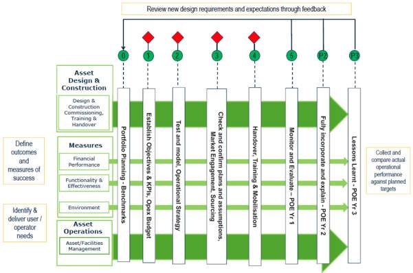
Government soft landings (GSL) were brought in alongside the mandating of BIM on public sector project by 2016 Lane (2013). The purpose of GSL is to acutely define the expectations of public sector projects and ensure that these expectations become reality BIM task group (2013). The aim is to produce a smooth transition from the Design and Construction phase to the operation phase of a built asset, which is combined with post-occupancy evaluations (POE), and looks to give a comparison between required performance requirements/outcomes and actual performance outcomes GSL (2016).
The early engagement of the end users and the inclusion of a GSL champion aids in a key part of the BIM level 2 process. GSL is an improved version of soft landings which is well known within the construction industry. The key difference is the introduction of POE’s to help complete the virtual full circle from design and construction to operation with the end user’s involvement a crucial factor Davidson (2015). Lessons learned are included into a client’s BIM library and can be used in future projects streamlining projects. The diagram below shows gives a visual breakdown of the stages that are covered under the umbrella of GSL.
A major benefit of GSL how it ties into BIM level 2 helping to inform the project team of performance requirements. GSL champions are involved from the very first stage of the project which helps to feed information into asset datasets allowing for more accurate and predictable performance Davidson (2015). BIM level 2 and GSL sit hand in hand with each other and to get the best results from a project the inclusion of GSL is of major benefit Furey (2014).
One of the issues with GSL is its adoption by the construction industry. Davidson (2015) and Gough (2016) both state that the uptake of GSL has been reluctant and slow with contractors not using it because their clients haven’t asked for it. Gough (2016) proposes that although both BIM level 2 and GSL are mandatory as of April 2016, there has been more of a drive for BIM implementation and the construction industry has ‘neglected’ to look at GSL. Ultimately for GSL to work it needs to be applied alongside BIM level 2.
Another challenge to the protocol is raised by Lane (2013) who argues that Clients are under the impression that including GSL in the BIM process will cost them more.
Case Study: Ministry of Justice, Liverpool
An example of the benefits of using government soft landings was that of the kitchen refurbishment at Ministry of Justice (MoJ) – Liverpool local prison. Post Occupancy Evaluations (POE) were carried out following the completion of the new kitchen, using structured questionnaires to question key staff. The POE’s created a starting point for the kitchen design library which when linked with BIM data and lessons learned helped to identify areas for kitchen efficiency. Via the use of BIM and GSL the Ministry of Justice were able to reduce capital costs by £270K (BIM task group, 2017).
2.7 Digital Plan of Work (DPOW)
With the introduction of the BIM Mandate in April 2016, there is an increasing accumulation of digital data within the design and construction process, and therefore a need to create a way of managing and understanding this information in both a constructive and industry standardised manner.
The DPOW is an essential BIM tool in both project delivery (PAS 1192-2) and asset management (PAS 1192-3) as it defines the project work stages, the project deliverables and the level of detail required from each design team member at each of the work stages from inception through to operation. The DPOW also collects structured digital data from a construction project which may then be employed within an asset management system i.e. Asset Information Model (AIM) (NBS, 2016).
Developed by the BIM Task Group and in line with the RIBA POW 2013 work stages (Figure 1), the DPOW provides clarity on how built asset data is defined and successfully used to achieve BIM Level 2 (ibid).

Figure 8 – RIBA Plan of Work 2013 Stages
The NBS BIM Toolkit provides a free to use digital plan of work accessible online to members of the design team, which enables information deliverables and responsibility to be clearly defined, assigned and understood. All deliverables within the Toolkit have been arranged by Uniclass 2015, additionally a classification-mapping strategy has been adopted to create specification reference codes i.e. mapping against RICS NRM1, providing a clear method of specification across multi-disciplinary team members. All members of the project team may access the DPOW as contributors, enabling collaborative working by providing an online platform which allows project information and comments to be shared and viewed in one digital place specifically design for the built environment (NBS, 2017).
BIM Level 2 is distinguished by collaborative working, where all parties within the design and construction process work together sharing information but do not necessarily work within one model. As the project deliverables need to be carried out sequentially to allow collaborative working, the DPOW facilitates this by ensuring that the right information is produced at the right time using a standardised process which all members of the design team understand (NBS, 2017).
The DPOW has been developed to avoid confusion and inconsistencies within design process which may arise from multi-discipline specific ‘plans of work’, overlapping project tasks/deliverables and increased levels of ‘BIM’ data (CIOB, 2015).
The DPOW provides the framework for informed and consistent decision making by all members of the design team at each work stage of the project. It enables collaborative working and effective decision making through the clear definition and clear allocation of responsibility of project deliverables (NBS, 2017).
What clients really think is a key article in understanding the potential barriers of the DPOW. Figure 2 illustrates the results from a survey taken directly from the report regarding the experiences of using the DPOW. Views expressed within the report indicate that the DPOW is viewed as a tool that is untested and therefore there is uncertainty in using it on a live project.
Figure 2: NBS DPOW User Survey (CIOB, 2016)
2.8 Classification
The components within a BIM model must be classified to be identifiable by all stakeholders for the purposes of measurement, specifying, procurement and building maintenance. Uniclass 2015 offers a standardised information classification system. This provides a common language between the project stakeholders via integration with the DPOW (Herbert Smith Freehills LLP, 2016). It is mapped to NRM1, compliant with ISO 12006-2 and supports integration with other classification systems in the future (NBS, 2016)
Classification is essential to realising effective information management. It has been acknowledged as one of the eight pillars required for implementing building information modelling (BIM) level 2. (NBS, 2017)
With BIM producing a vast amount of information or data, it can be a very powerful resource. However, if the model cannot find a particular piece of information or data when it is needed, then that potential may never be realised. (Gelder, 2015)
Classification can be defined as, ‘The act or process of dividing things into groups according to their type.’ Classification has been used for many years in the construction industry, frequently without the users’ knowledge (Gelder, 2015). Uniclass was derived from this classification and gave the prospect to classify information or data in different ways. It was based on a simple structure described in ISO 12006, which relates to the use of classification classes. (Delaney, 2017)
Uniclass 2015 is a unified classification covering all construction sectors across the UK construction industry. It comprises of consistent tables classifying items of all scale from facilities such as a railway to products such as CCTV camera’s in railway stations (Delaney, 2017).
As part of the BIM toolkit project, NBS have worked on the current Uniclass 2015 scheme. Originally released in 1997, the original has been heavily revised to make it more compatible with BIM and more suitable for use with modern construction industry practice (Delaney, 2017).
Uniclass 2015 builds on previous versions but responds to industry feedback and significantly extends the scope. Unicalss 2015 provides:
- A unified classification system for the construction industry. Buildings, infrastructure, and landscape can be classified under one unified scheme.
- A classification system that NBS will maintain and update.
- A flexible numbering system to accommodate future classification requirements.
- A database of synonyms within the BIM toolkit to make it as easy as possible to find the required classification using standards industry terminology.
- A classified suite of tables that support classification from a hospital or road network to a ceiling tile or kerb unit.
- A system that is mapped to NRM1 and supports mapping to other classification systems in the future, that is also compliant with ISO 12006-2. (Delaney, 2017)
The classification system can be used to annotate objects in a graphic model (Uniclass, 2017). Different things and items such as whole complexes, catalogues and individual products can add further classification codes.
Items can be drawn into schedules and drawings through classification codes, as the codes are collected together in order to carry out different types of analysis. For example, different types of conference rooms can be gathered together, which allows the total amount of space allocated to conference rooms to be assessed. (Uniclass, 2017)
Uniclass 2015 is divided into a set of tables in order to categorize information for briefing, costing, CAD layering etc. in addition to preparing production products or specifications. The tables are also appropriate for buildings and other assets in use, and maintaining facilities management and asset management information (Delaney, 2017).

Figure 9 – Uniclass Tables
Figure 9 above demonstrates how the tables are broadly hierarchical, which in turn allows information about a project to be defined from the broadest view to the most detailed (Delaney, 2017). The complexes can be thought of in terms of the provision of an activity as it describes the projects in overall terms. Complexes can be broken down as groupings of activities, spaces, and entities depending on the use. The groupings are further broken down into elements, systems, and products to give the item or product more detail and a code that will be specific to that item (Delaney, 2017).
Gelder, (2015) describes Uniclass 2015 as a classification system like no other in the construction industry. As it serves the entire project timeline, it is discipline neutral and sector neutral, it has a logical physical object hierarchy, it aligns with ISO 12006-2:2015, its objects can be mapped to definitions and synonyms, it is consistent between and within tables, and is relatively simple to use (Gelder, 2015).
Using this classification system within BIM provides a rich information model which aside from graphical data, also includes non-graphical information such as associated documentation, performance requirements, and is presented in a specification or manual format (Mordue, 2015). This combination of graphical and non-graphical information provides an overall picture (Mordue, 2015).
Furthermore, the Government’s Soft Landings guidance endorses that a buildings operation phase should be considered throughout the whole project lifecycle (Mordue, 2015). Actual performance outcomes can be compared through establishing the required operational budget and performance outcomes at an early stage. Using similar products or similar ‘things’ by identifying them through the Uniclass 2015 classification systems, will support at the design stage by identifying the different product lifecycle performances of different products or ‘things’, in order to provide the team with the greatest possible options for the lifecycle of the building (Manning, 2015)
A case study by Oduyemi (Oduyemi, 2017) demonstrated that BIM-compatible tools such as classifications can immensely help designers achieve low running cost, good environmental rating, lower life cycle costs, low carbon house, if various what if scenarios (sensitivity analysis) are properly evaluated at the early stage of the design using different products or things, when the cost of change is at the cheapest (Oduyemi, 2017).
Finally, Manning (2015) states that “for the implementation of Level 2 BIM in the UK, a cross-sector, full lifecycle classification system is essential.”
3.0 BIM Level 3
The majority of the industry has now transcended Level 1 and primary adopts the BIM level 2 approach, this is partly due to the government mandating in 2013 that all government funded projects should employ this method by 2016. Approximately 80% of the cost of an asset occurs in the operational/facility management stage, therefore it is crucial to highlight and implement the need for greater efficiencies in the design and build phase. This is something that BIM level 2 has focused on and as a result it is thought to have reduced construction costs by up to 20%.
Targeting the functional performance of an asset regarding a higher level of efficiency is thought to increase the efficiency in other areas and boost social factors. BIM level 2 highlights the importance in seeking out technologies, materials and construction methods that are beneficial regarding the whole life cycle of the building and as a result projects that utilise this programme continue to run a lot smoother and trouble free for a longer period compared to those that don’t.
As mentioned, BIM level 2 is effective at boosting the overall efficiency and reducing any clashes that may arise during the design stage of a project, however, its applications are limited when regarding problems during the construction process. The handoff phase is where the shortcomings of level 2 are most apparent due to the lack of collaboration and as a consequence can create the following:
- Data silos
- Errors
- Version control problems
- Rework
Essentially the data from the design phase doesn’t integrate into the rest of project stages, this can cause the architect to lose influence over their design and also inhibits the construction teams from being fully collaborated into the design.
The construction industry traditionally consists of four main teams; the design team, construction team, supply team and operations team. All too often they fall under the process of siloed construction (figure 2) in which task management, feedback loops and design coordination’s are usually confined between the professions of each separate team therefore there isn’t any extensive collaboration, which undermines the very thing BIM sets out to achieve. The framework of level 2 unfortunately does nothing to prohibit siloed construction and therefore is prone to suffer from a lack of data integration, disconnected documents and insufficient data for process simulation, all three have been identified as the root cause of project delivery issues. Research by the UK industry council has stated the current vision of reducing costs, increasing value and boosting sustainability cannot be achieve by BIM level 2 alone (2).
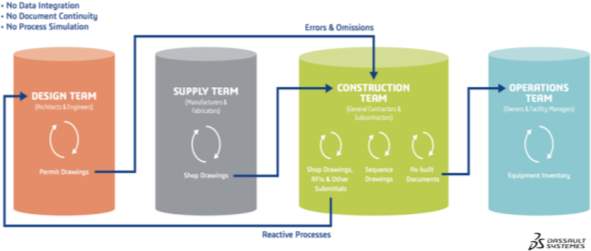
Figure 10 – Data Silos in Construction
BIM Level 3 is the most advanced and up to date stage of BIM that seeks to promote full collaborative working across all disciplines using a single, shared project model held centrally and accessible to all to modify and share data. A project that adopts the methodology of BIM Level 3 will allow all parties to access the same working model, in doing so removing the risk of conflicting information, this process is known as ‘Open BIM’. Ultimately, Open BIM hopes to be responsible for completely removing the risk of clashes throughout all phases and support the development of whole life cycle approaches. Designs created through BIM level 3 are predicted to achieve the following:
- Provide more for less – this highlights the use of utilising more modern and efficient technologies to withdraw and extend the potential of the existing infrastructure. Finding ways to enhance the public services via the economic and social infrastructure with little investment is just one of the challenges BIM level 3 has to deal with.
- Maximise availability – this highlights the need to implement monitoring technologies to perform a continuously assessment on the condition of any assets. Understanding the operational efficiency of any given system is crucial in determining the best course of action regarding how and when to issue maintenance. This is thought to maximise the time that facilities and networks are available to the public domain.
- Reduce carbon and whole life cycle costs – highlights the needs to implement better business models and supply chains that deliver engineering and construction services more efficiently.
- Boosts domestic and international growth – seeks to adopt, support and utilise UK businesses at all levels on the supply chain and hopes to broaden their local and global customer base.
- Ensures the UK remains in the international vanguard – highlights the need for the UK to develop, deploy and capitalise on the digital economy in order to expand the profile and market opportunity, this is especially relevant in the areas of social services and the built environment.
There are four proposed stages for how BIM level 3 will be implemented across the coming years and eventually evolve into BIM level 4:
- Level 3A – enabling improvements in the level 2 model
- Level 3B – enabling new technologies and systems
- Level 3C – enabling the development of new business models
- Level 3D – capitalising on world leadership
A new model has been introduced that will see the continuous collaboration between all teams and effectively eliminate siloed construction from the industry as viewed in figure 3. The continuous workflow model allows every party to input relevant data in the context of their specialised profession into each phase of the project.
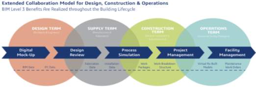
Figure 11 – BIM level 3 extended collaboration model for design, construction, and operations
The extended collaboration model in figure 11 is made up of several distinct processes that are:
Digital mock – up (DMU): involves the modelling of all proposed systems within the building, this sets the stage for a clear manufacturing context of which better design decisions can be made by the team.
Design Review: this takes the different models created in the DMU process and combines them in one single platform model in order to check for any clashes within the design i.e. pipes running into structural members etc.
Process Simulation: this allows the project team to make key decisions based the methods and means of construction. By running these test simulations the team can identify even the most obscure and minor errors, it can also help on deciding what course of action is the most time and cost effective.
Project Management: this synchronizes data from the DMU with enterprise recourse planning (ERP) systems in order to monitor the project by ensuring it keeps in line with the original plan, issues invoices on a milestone basis, tracks labour costs and manages material expenditure.
Facility Management: BIM data is synchronized with facility management systems to create a living data set that can be archived. This helps to guarantee equipment is operated and maintained in the most energy efficient way, and reduces the amount of time spend searching for key facility information.
In order to optimise the full effectiveness of BIM level 3 industry leaders are advocating the use building lifecycle management system (BLM) alongside the extended collaboration processes. It is thought the benefits of which include:
Improved productivity – using a BLM will help protect a project from falling under the risk of version control issues as well as mitigating the risks of human error on the design/operation phases. Having all users gain access to the same live database enables them to apply real time solutions and will significantly reduce the need for reworks and FRIs (Requests for information).
Increase quality and value from suppliers – A BLM will grant the designers with more in depth data context and control leading them to make better design decisions and ultimately improve the overall quality of the finished product. More access to reliable data allows builders and suppliers to improve coordination and execute plans more quickly.
Reduce waste, risks and costs – Traditional construction methods are responsible for cost over-runs in the region of around 15-30% and standard risk margins of around 20% or more, highlighting the need for improvement. A BLM strategy is designed to reduce waste by more accurately predicting outcomes, identifying potential points of conflict, and optimizing processes. It also aims to reduce the financial and health risks associated with project schedule, worker safety, and overall construction budget.
Gain a competitive advantage – there is an opportunity for architecture, engineering and construction firms to gain an advantage amongst their competitors if they embrace BIM level 3 as soon as possible. Understanding and applying a BLM system will allow the team to deliver higher quality works, gain the loyalties of owners and design partners, and retain a healthier profit margin than most of the industries companies that do not use BIM.
Façades are typically a costly component to any project, typically resulting in around 15% of the construction budget. It has been stated that the costs associated with manufacturing façade models can be reduced by 50% is defined in the design stage. BLM allows designers and manufactures to collaborate on such issues and as a result costs are reduced and supply chain efficiency is increased, benefiting the overall project.
A case study in Hong Kong reviewed the construction of the 70-story One Island East Tower that was designed using the BIM level 3 method. The project was completed on time and with zero cost overruns. Prior to its construction the team identified over 2000 issues in the design that where all resolved thanks to the benefits of utilising BIM. Compared to a 2D design process the number of Requests for information (RFIs) showed a reduction of 93%. The project went onto win the 2008 AIA Technology and Practice Award.
Digital Built Britain and BIM Level 3
Digital built Britain is somewhat synonymous to BIM level three and has been described by the government as the next phase to building information modelling. Digital built Britain is the government’s proposed plan to fully integrate BIM level 3 into the industry and by the end it aims to change the traditional way of designing and producing infrastructure projects by implementing the following:
- A platform from which all parties, suppliers and relevant stakeholders can engage in finding the best solutions to whole life cycle problems on an infrastructure project, this platform also puts them in a position to be able to bid to supply projects with the necessary solutions.
- Challenging the existing roles of suppliers, contractors and consultants in order to improve technical issues and reduce costs.
- Create a better business model from using a wider array of service performance data. Doing this will allow for more detailed plans regarding infrastructure and asset design, delivery, operation and adaptation.
- Greater security regarding the protection of data, due to the increase in shared data ensuring proper security measures are in place will make it easier to deter, detect or mitigate any incoming threats.
The proposed business model in figure 4 shows how processes used in level 2 will evolve into BIM level 3, as one can see the model intends to split the data up into three primary datasets that are concerned with the operation, delivery and performance management phases of the programme/project.
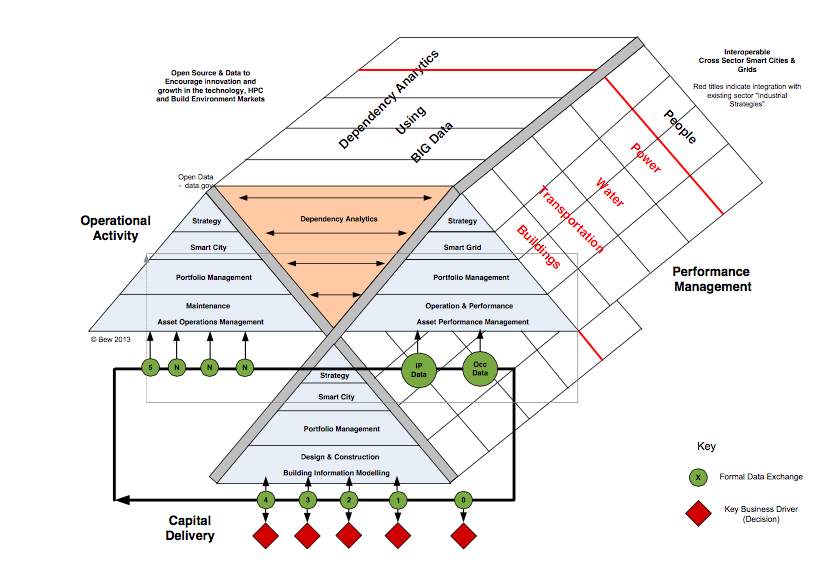
Figure 12 – Digital Built Britain Operational Model
As data transverses further up the pyramids it use will become more strategic and applicable to other projects, it will be stored and published via data.gov and other security approved organizations so that its access can be made available to the market for all to use and ultimately act as the foundation for BIM level 4.
How will the future look under BIM Level 3?
From a client’s standpoint, this will enable them to use technologies and techniques in order to develop a collaborative relationship with their suppliers. All teams can cohesively collaborate in the development of technical solutions problems that will be digitally prototyped ahead of a commitment to significant capital expenditure. The area of digital collaboration is predicted build a basis for the establishment of new businesses that could use the opportunity to develop technologies in order to meet the whole life cycle requirements. Businesses that specialise in these technical solutions could be sought elsewhere around the globe and collaborate with other infrastructure companies, this would in part meet the aforementioned goal of boosting local and global economies. Some solutions that BIM level 3 is advocating are being practiced today such as the following:
- The integration of infrastructure mapping with control units in things like cars or public transport, this can be used in order to maintain positions in lanes and distances between vehicles thus mitigating the risk of collisions and increasing the capacity of networks. Companies like Tesla that produce driverless cars are an example of a technology that utilises this method and is expected to become more widespread in the coming years.
- The use of 3D printing and other fabrication techniques to provide components for infrastructure projects, one example refers to Sellafield nuclear power plant. A new lid was designed to seal a 40 tonne solid waste export flask, under normal circumstances the lid would have cost around £25,000 due to its rarity, however, the lid when produced via 3D printing only cost £3,000, therefore the price of many expensive components could be reduced significantly thanks to this solution.
- Use of embedded sensors and other features of the Internet of Things to monitor the condition of infrastructure and predict the need for maintenance interventions, creating a feedback loop back to the asset brief, enabling the opportunity to invoke performance contracts and reporting
References
BSI. (2014). Specification for information management for the operational phase of assests using building information modelling. London: British Standards Institution.
BSI. (2015). Specification for security-minded building information modelling, digital built environments and smart assest management. London: British Standards Institution.
CIC/BIM Task Group. (2013). Building Information Model (BIM) Protocol. London: Construction Industry Council.
CIOB. (2015). RIBA Plan of Work 2013 versus Digital Plan of Work: What you need to know. Retrieved from Bim Plus: http://www.bimplus.co.uk/management/ribaplan-work-2013-v-d5igital-pla3n-w4ork-what/
CIOB. (2016, August 8). BIM: What clients really think. Retrieved from https://toolkit.thenbs.com: CIOB. (2016). BIM: What clients really think. London: Atwww.nbs.com:/articles/an-introduction-to-the-toolkit
Delaney, S. (2017, January 18). Classification. Retrieved April 14, 2017, from NBS BIM Toolkit: https://toolkit.thenbs.com/articles/classification/
Gelder, J. E. (2015). The Design and Development of a Classification System For BIM. (U. o. L. Mahdjoubi, W. I. C.A. Brebbia, & R. G. R. Laing, Eds.) Building Information Modelling (BIM) in Design, Construction and Operations, 149, pp. 477-491.
Gleeds. (2014). Gleeds: Thinking About BIM Paper 8. Retrieved April 7, 2017, from Gleeds: https://www.gleeds.com/assets/Global/DownloadThinking_about_BIMpaper_8.pdf?1426594564
Herbert Smith Freehills LLP. (2016, 03 04). Construction: The eight pillars of BIM. Retrieved from www.lexology.com: http://www.lexology.com/library/detail.aspx?g=bde9dd73-020d-420d-969e-08ed814828da
Manning, R. 1.-7. (2015). NBS National BIM Report 2015 . Completing BIM Level 2, 4-7.
Mordue, S. (2015). NBS National BIM Report 2015. Levels of BIM Information, 22-25.
NBS. (2016, 03 10). An Introduction to the Toolkit. Retrieved from www.thenbs.com: https://toolkit.thenbs.com/articles/an-introduction-to-the-toolkit
NBS. (2016, 11 02). Classification. Retrieved from www.toolkit.thenbs.com: https://toolkit.thenbs.com/articles/classification
NBS. (2017). Retrieved from https://www.thenbs.com/knowledge/bim-levels-explained
NBS. (2017, March 14). What is the Digital Plan of Work? Retrieved from www.nbs.com: www.thenbs.com: www.thenbs.com/knowledge/what-is-the-digital-plan-of-work
NBS. (2017). What is Uniclass 2015? . Retrieved April 14, 2017, from NBS Online: https://www.thenbs.com/knowledge/what-is-uniclass-2015?utm_medium=email&utm_source=2017-03-30_eweekly&utm_campaign=Construction%20classification%3A%20Uniclass%20decoded
Oduyemi, O. O. (2017). The application and barriers of BIM in sustainable building design. Journal of Facilities Management, 15-34.
RICS. (2014, 11 13). What is BIM? Retrieved from www.rics.org: Building information modelling gets people and information working together effectively and efficiently through defined processes and technology (RICS)
Al Ahbabi, M., and Alshawi, M. (2015). BIM for client organisations: a continuous improvement approach. Construction Innovation [online], v. 15 (4) p. 402-408
Available at: http://www.emeraldinsight.com/doi/abs/10.1108/CI-04-2015-0023
Accessed: 9th April 2017
Ashworth, S., Druhmann, C., and Tucker, M. (2016) The Role of FM in Preparing a BIM Strategy and Employer’s Information Requirements (EIR) to align with Client Asset Management Strategy. [online]. European Facility Management Conference, Milan, June 2016.
Ashworth, S., Druhmann, C., Kassem, M., and Tucker, M. (2016a) Integration of FM expertise and end user needs in the BIM process using the Employer’s Information Requirements (EIR). [Online]. European Facility Management Conference, Milan, June 2016.
BIM plus (2015) Case Study: National Graphene Institute [online],
Available at: http://www.bimplus.co.uk/projects/pushing-bim-boundaries/
Accessed 8th April 2017
BIMtaskgroup (2013) Employer’s Information Requirements – Core Content and Guidance Notes [online].
Available at: http://www.bimtaskgroup.org/wp-content/uploads/2013/04/Employers-Information-Requirements-Core-Content-and-Guidance.pdf
BIFM (2017) Employer’s information requirements (EIR) An overview of facilities management requirements [online].
Available at: http://www.bifm.org.uk/bifm/filegrab/1bifm-eir-overview-v9.pdf?type=documents&ref=6174
British Standards Institution (2013). PAS 1192-2:2013 Specification for information management for the capital/delivery phase of construction projects using building information modelling. [online] London: British Standards Institute
Available at: http://shop.bsigroup.com/Navigate-by/PAS/PAS-1192-22013/
British Standards Institution (2014). PAS 1192-3:2014 Specification for information management for the operational phase of assets using building information modelling. London: British Standards Institute
Available at: http://shop.bsigroup.com/forms/PASs/PAS-1192-3/
Construction Manager Magazine (2017) CM round table: What happened to the BIM bang? [online]
Available at: http://www.constructionmanagermagazine.com/agenda/cm-round-ta7ble-wh8atever-happ9ened-bim-bang/
Accessed 10th April 2017
Dawood, H., Dawood, N., Khalid, N., and Rodriguez-Trejo, S. (2017). Hierarchy based information requirements for sustainable operations of buildings in Qatar. Sustainable Cities and Society [online], Accepted manuscript.
Available at: http://www.sciencedirect.com/science/article/pii/S2210670716307119
Accessed 9th April 2017
NBS (2011) BIM Implementation – HOK buildingSMART [online]
Available at: https://www.thenbs.com/knowledge/bim-implementation-hok-buildingsmart
Accessed: 9th April 2017
The B1M (2015). Pillar 1: PAS 1192-2 | The 8 Pillars of BIM Level 2. [online video]
Available at: https://youtu.be/89ICytBBCos
Accessed: 8th April 2017
The B1M (2015a). The 8 Pillars of BIM Level 2 – An Introduction | The B1M [online video]
Available at: https://youtu.be/8ux4euF4BVs
Accessed: 8th April 2017
The B1M (2015b). What are Employer’s Information Requirements? | The B1M [online video]
Available at: https://youtu.be/VwMe2cM8t_M
Accessed: 8th April 2017
Dassault Systems (n/a) End-to-End Collaboration Enabled by BIM Level 3 [online]
Available at: https://ifwe.3ds.com/sites/ifwe/files/2016-06/asset-aec-pdf-bim-level-3-en_1.pdf
[Accessed: April 2017]
British Standards Institution (n/a) The Birth of BIM [online]
Available at: http://bim-level2.org/globalassets/pdfs/uk-guide-chapter-1-introduction.pdf
[Accessed: April 2017]
HM Government (2015) Design Built Britain: Level 3: Building Information Modelling – Strategic Plan [online]
Available at: http://digital-built-britain.com/DigitalBuiltBritainLevel3BuildingInformationModellingStrategicPlan.pdf
[Accessed: April 2017]
NBS (2014) BIM Levels explained [online]
Available at: https://www.thenbs.com/knowledge/bim-levels-explained
[Accessed: April 2017]
NBS (2017) Four things Mark Bew told us about the future of BIM and digital construction [online]
Available at: https://www.thenbs.com/knowledge/four-things-mark-bew-told-us-about-the-future-of-bim-and-digital-construction
[Accessed: April 2017]
Eastman, C., Teicholz, P., Sacks, R. and Liston, K. (2008), BIM Handbook: A Guide to Building
Information Modeling for Owners, Managers, Designers, Engineers, and Contractors, John
Wiley & Sons Inc., Hoboken, NJ
Barlish, K. and Sullivan, K. (2012), “How to measure the benefits of BIM – a case study approach”,
Automation in Construction, Vol. 24, pp. 149-159.
Bryde, D., Broquetas, M. and Volm, J.M. (2013), “The project benefits of building information
modelling (BIM)”, International Journal of Project Management, Vol. 31 No. 7, pp. 971-980.
Supply chain integration with BIM: a graph-based model
Papadonikolaki, Eleni; Vrijhoef, Ruben; Wamelink, Hans. Structural Survey; Bradford 33.3 (2015): 257-277.
Demian, P. and Walters, D. (2013), “The advantages of information management through
building information modelling”, Construction Management and Economics, Vol. 32 No. 12,
pp. 1153-1165.
BIM Task Group (2017) GSL Case Studies. [online] Available at: http://www.bimtaskgroup.org/gsl-case-studies/. [Accessed 26/07/17.
BIM Task Group (2013) Government Soft Landings. [online] Available at: http://www.bimtaskgroup.org/gsl/. [Accessed 25/04/17].
Davidson, S (2015) Government Soft Landings: Bigger than BIM?[online] Available at: https://www.constructionnews.co.uk/government-soft-landings-bigger-than-bim/8677468.article. [Accessed 26/04/17].
Furey, J (2014) Government Soft Landings: Are we ready to take off? [online] Available at: http://bakerstuart.com/government-soft-landings-ready-take/.
Government Soft Landings (GSL) (2016) Government Soft Landings – BIM Task Group[online] Available at: www.bimtaskgroup.org/wp…/Government-Soft-Landings-Section-1-Introduction.pdf. [Accessed 25/04/17.
Lane, T (2013) Government Soft Landings: Strings attached [online] Available at:http://www.building.co.uk/government-soft-landings-strings-attached/5058049.article. [Accessed 25/04/17].
Willmott Dixon (2015) Soft Landings[online] Available at: www.willmottdixon.co.uk/asset/download/10427. [Accessed 25/04/17].
Arayici, Y. (2012). BUILDING INFORMATION MODELLING (BIM) IMPLEMENTATION AND REMOTE CONSTRUCTION PROJECTS. Charles Egbu, 75-92.
BIFM. (2015, Sept). BIM Academy. Retrieved from BIM Academy : http://www.google.co.uk/url?sa=t&rct=j&q=&esrc=s&source=web&cd=7&ved=0ahUKEwic0rSm7brTAhUJYVAKHRduBHEQFghTMAY&url=http%3A%2F%2Fwww.bifm.org.uk%2Fbifm%2Ffilegrab%2Fbifm-casestudy-bimx3-v11-final-25.9.pdf%3Ftype%3Ddocuments%26ref%3D5709&usg=AFQjCNH9QjzTXukT
ICE. (2016, Oct 27). BS 1192-4:2014. Collaborative production of information Part 4: Fulfilling employer’s information exchange requirements using COBie – Code of practice. Retrieved from ICE: https://www.designingbuildings.co.uk/wiki/BS_1192-4:2014._Collaborative_production_of_information_Part_4:_Fulfilling_employer%E2%80%99s_information_exchange_requirements_using_COBie_%E2%80%93_Code_of_practice
JCT. (2016). Building Information Modelling (BIM), Collaborative and Integrated Team Working. London: Thomson Reuters.
Latiffi, A. A. (2015). Roles and Responsibilities of Construction Players in Projects Using Building Information Modeling (BIM). Mohamad Syazli Fathi, 112-121.
Özdemir, D. E. (2015). Building Information Modeling in Project Management: Necessities, Challenges and Outcomes. Dr. Cemal Zehir, 87-95.
RICHARDS, M. (2010, Mar ). ICE . Retrieved from PAS 1192-2: https://www.designingbuildings.co.uk/wiki/PAS_1192-2
Salman Azhar, M. H. (2014). Building Information Modeling (BIM): Benefits, Risks and Challenges . Blake Sketo , 222-232.
Cite This Work
To export a reference to this article please select a referencing stye below:
Related Services
View all


Related Content
All TagsContent relating to: "Community Development"
Community development is defined by the UN as "a process where community members come together to take collective action and generate solutions to common problems".
Related Articles

DMCA / Removal Request
If you are the original writer of this dissertation and no longer wish to have your work published on the UKDiss.com website then please: