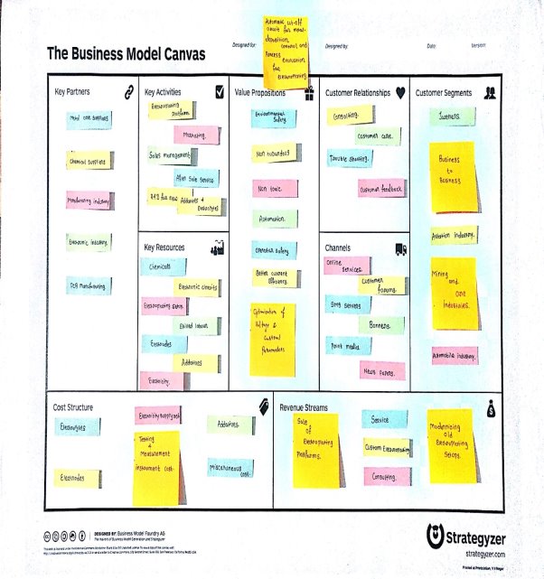
Automatic Cut-off Circuit for Metal Deposition Control and Process Evaluation for Electroplating
Info: 8513 words (34 pages) Dissertation
Published: 16th Dec 2019
Tagged: EngineeringElectronics
ABSTRACT
Electroplating is a generally used as a finishing process, depositing one metal over another. Modern manufacturing processes require better deposition control and surface finish. The project aims to develop an electric circuit that controls the metal deposition on cathode for electroplating. The circuit cuts off the power supply after desired thickness of metal is plated over cathode, thus automating the process of electroplating. The electroplating apparatus would then be used for process evaluation of copper electroplating using non-cyanide electrolytic bath using Monosodium glutamate as complexing agent.
Keywords: Electroplating, Copper Plating, Automatic Cut-Off Circuit, Complexing Agents, Monosodium Glutamate.
TABLE OF CONTENTS
LIST OF SYMBOLS AND NOMENCLATURE
1.2 Terms related to electroplating
1.3 Principle of Electroplating
1.3.1 Process of electroplating
2.1 Non-cyanide copper electroplating bath glutamate as additive
2.2 Electroplating of Copper on Steel in Gluconate bath
2.3 Chemical etching of Copper
2.4 Environment friendly non-cyanide electroplating bath
2.5 Properties of electrodeposited copper, their relation with electrodeposition parameters
2.6 Influence of complexing agents on texture of copper plating
Chapter: 3. Electroplating apparatus
3.1 Existing electroplating setup
3.2 Upgradation with automatic cut-off circuit.
3.2.1 Construction of the cutoff-circuit
3.3.1 Description of the Micro-controller board and Peripheral components.
3.3.2 Simulation of the circuit.
3.4 Final setup with the cut-off circuit
3.4.2 Connections with the apparatus
Chapter: 4. Experimental Analysis
4.1 Evaluation of the MSG bath
4.1.1 Preparation of electrolytes
4.1.2 Preparation of cathode samples
4.2 Repeatability testing of the cut-off circuit
4.2.1 Methodology of the experiment
4.2.2 Theoretical calculation by Faradays law.
LIST OF FIGURES
Figure 1‑1 Deposition of metal ion during electroplating
Figure 2‑1 Effect of etchant on surface roughness
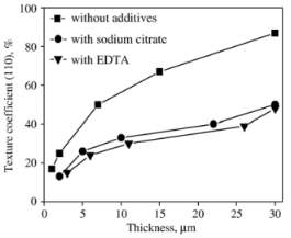
Figure 2‑7 TC110 change by the thickness of copper electrodeposited
Figure 2‑8 TC111 change by the thickness of copper electrodeposited
Figure 3‑1 Existing Electroplating setup
Figure 3‑3 Printed Circuit Board
Figure 4‑1 An electroplating sample
Figure 4‑2 Electroplating samples for repeatability test of the cut-off circuit
LIST OF TABLES
LIST OF SYMBOLS AND NOMENCLATURE
Nomenclature:
I
: Current
V
: Voltage
t
: Time
M
: Molarity
F
: Faraday’s constant
E°
: Standard electrode potential
J
: Current density
m
: Mass
ϕ
: Diameter
ρ
: Density
t
: Thickness
Z
: Electrochemical equivalent
Subscripts:
Abbreviations:
MSG
: Mono-Sodium Glutamate
C.E
: Current efficiency
Chapter: 1. Introduction
1.1 Current scenario
Electroplating is a metal finishing process that is used to deposit a layer of metal onto the surface of another substrate with the help of electricity. It is generally carried out to deposit metals like gold, silver, copper, nickel and zinc, which are some of the most widely used metals for plating.
Many new plating methods are also developed that do not require electricity for deposition. Such methods fall under the category of electroless plating, which is used to plate very thin layer selectively for electronics manufacturing. [1] Steel is the most important material from the point of application in electroplating in manufacturing industry. Steel is plated with zinc, copper and nickel for various applications. In Automobile industry steel is plated with Chromium to have lustrous look along with anti-corrosion properties.
1.2 Terms related to electroplating
It is important to consider some terms that are frequent in electroplating and the conventions.
Electrolyte : An Electrolyte is a solution that conducts electricity through it and contains ions of the metal that is to be deposited by electroplating.
Electrodes : Electrodes are conductive terminals dipped in the electrolyte for passing current. An electrode connected to a positive terminal is called anode, while the one connected to negative terminal is cathode.
Additives : Additives are other substances added in small amounts to the electrolyte for enhancing the process of electroplating. Additives are of different types namely complexing agents, inhibitors, reagents etc.
Current efficiency : The ratio of actual metal deposited on the cathode to that calculated by the faraday’s law is known as current efficiency.
1.3 Principle of Electroplating
The electroplating process is very simple in nature and essentially consist of charge passing through an electrolyte between two electrodes. This leads to redox reactions at anode and cathode resulting in electroplating.
1.3.1 Process of electroplating
The deposition of metal by electroplating is governed by Faradays laws which are stated as follows:-
- The mass of substance deposited is proportional to the charge passed through the electrolyte
- For the same amount of charge the mass of substance deposited is proportional to its equivalent weight.
The electrolyte solution is dissociated by passing of electric current into cations and anions. The metal ions that are dissociated by electrolysis deposit onto the substrate that acts as cathode, by passing of electric current. The ions from the electrolyte gets deposited on the cathode and ions from anode gets consumed into the electrolyte to maintain the concentration.
1.3.2 Cathodic deposition
The deposition of metal onto the Cathode substrate is known as Cathodic deposition. The deposition of metal on the cathode can be seen in three stages. [2]
- Ionic migration: The metal ions in the solution migrate towards cathode under the influence of electric field or by convection.
- Electron Transfer: The metal ion orients itself along with the hydrate ions or complex additives on the cathode and accepts an electron to neutralize in the diffuse zone.
- Incorporation: The metal atom is incorporated into the growing metal lattice over the substrate.
![C:UsersDHARMAJIANDesktopelectroplATINGelectroplating research papersmetal deposition [wiley].JPG](https://images.ukdissertations.com/10/0007618.004.jpg)
The process of metal deposition from the solution is depicted below. [3]
Deposition of metal on an electrode is given by the following reaction.
Msolutionz++ze→electrodeMlattice
1.4 Electroplating of Copper
Copper is one of the most widely plated materials. This is because copper is used as base plate for covering imperfections for plating other materials, has high plating effciciency and highly conductive. [3] industries today copper plating is done with acidic or basic cyanide baths. Copper plating is seldom done with pure Copper Sulphate electrolyte. Copper plating baths with variety of additives have been developed, the most widely used types are listed as follows:-
- Acid copper baths
- Fluoborate baths
- Cyanide baths
- Alkaline copper baths
- Pyrophosphate baths
1.4.1 Cyanide baths
Cyanide baths are most widely used in industrial copper plating applications compared to all other baths. This baths use Potassium Cyanide(KCN) as a complexing agent in Copper Sulphate solution. Cyanide baths give better better deposition, brightness and adherence of plated copper compared to pure copper sulphate bath. The current efficiency of cyanide baths is also higher. Cyanide ions form complexes with the Copper ions and is present in the form of [Cu(CN)3]-2 , [Cu(CN)2]-1, [Cu(CN)4]-3 in solution and aids its deposition. [4]
The drawback of cyanide baths is that it makes the electrolyte toxic and hazardous for the environment. Precaution is needed for its use and safe disposal. In many cases it needs to be treated and purified of cyanide for safe disposal, which involves stringent procedures. Cyanide sludge is treated by alkaline chlorination, UV light and electrolytic decomposition before disposal to waste water treatment. [5] Cyanide baths are used for plating thin copper strike over steel, which is less than 12.5 Microns thick. [3]
Due to these reasons alternative additives for copper plating are found which are not totally harmless or less hazardous than cyanide baths. Although use of such additives and baths other than the ones mentioned in the above section is currently limited for research and widespread implementation at industrial process is not seen.
Chapter: 2. Literature review
2.1 Non-cyanide copper electroplating bath glutamate as additive
New non-cyanide acidic copper electroplating bath based on glutamate complexing agent[6]
M.A.M. Ibrahima,b,,R.S.Bakdash
This is the first paper to evaluate the use of Mono-sodium Glutamate, an edible flavoring agent to be used as an additive in copper electroplating. The study was carried out to investigate the use of MSG as a complexing agent in acidic copper Sulphate baths.
The tests for MSG baths were done using potentiodynamic Cathodic polarization, cyclic voltammetry, in situ-anodic linear stripping voltammetry and chronoamperometry techniques. The samples for electroplating were then evaluated for its micro structure, hardness and adherence of copper deposits using various tests.
In the investigation it was found that MSG gives highly compact and adherent coatings at low current densities with current efficiency comparable to currently widely used cyanide baths. The MSG baths had a lower throwing power, which is the ability of an electrolyte to evenly coat the entire surface of a substrate in electroplating.
2.2 Electroplating of Copper on Steel in Gluconate bath
Electroplating of copper films on steel substrates from acidic gluconate baths[7]
S.S. Abd El Rehim, S.M. Sayyah, M.M. El Deeb
In this paper, acid gluconate bath for electroplating of the copper film on to the steel was investigated under different variable parameters like temperature of bath, pH value of the electrolyte, current density, and compositions added to bath.
There were experiments performed to analyze the effects of these above parameters on cathodic current efficiency, and the throwing power of the bath.
On the side of the experiment, they have used some standards to do the experiment to achieve most idle results, for the electrolyte the composition of CuSO4
∙5H2O, C6H11O7Na, and K2SO4 is made by using boubling Distilled water and analytical grade chemicals, For adjustment of pH level sulphuric acid and sodium hydroxide is used.
For experiments the cathode was polished by the 600-mesh emery paper and washed with distilled water, rinsed with ethanol then dried and weighed, surrounding temperature is kept in between
±1℃as required.
The electroplating duration is kept 15 min and after the electroplating cathode is withdrawn from the bath, washed with distilled water, dried, and weighed. Copper deposition were measures by using X-ray diffraction, For electroplating current supply is provided by using the DC power supply, pH were measured by pH meter.
2.3 Chemical etching of Copper
Chemical etching of Cu-ETP copper[8]
O. Ҫ akır, H. Temel, M. Kiyak
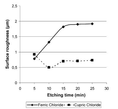
Chemical etching is the one of the oldest material removal process. Strong solutions are used as etchant which removes the excess material.
FeCl3and
CuCl2are mostly used as etchant. From the experimental results it is observed that
FeCl3etching provides the fastest chemical etch rate. And
CuCl2provides the smoothest quality.
FeCl3
is used as universal etchant.it can be used for steel, aluminium and its alloys, copper and nickel. Etching depth achieved by
FeCl3is more compared to
CuCl2.
Experimental results of surface roughness and time is given. Surface roughness is more in the substance using ferric chloride.
2.4 Environment friendly non-cyanide electroplating bath
New environmentally friendly noncyanide alkaline electrolyte for copper electroplating[9]
Z. Abdel Hamid, A. Abdel Aal
This research paper is basically on the use of alternative of cyanide in the electroplating process.
Sorbitol (C6H14O6) is used as an alternative (instead of cyanide) with NaOH and
CuSO4solution for the electroplating. Main benefit of using the sorbitol is that the coating of copper is very good quality with fine grain structure and it is environment friendly. Different experiments are conducted for checking the effects of temperature, current density and concentrations.
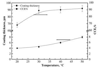
Figure 2‑2 Effect of temperature on the coating thickness and CCE% of copper layers deposited at 2 Adm-2 and 35 gl-1 sorbitol
It is observed that the thickness of copper plating increases with the temperature and current density increases up to
30℃then it becomes constant.
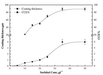
Figure 2‑3 Effect of sorbitol concentration on the coating thickness and CCE% of copper layer deposited from noncyanide bath at 20 °C, 2 Adm-2
Coating thickness is also having a linear relation with sorbitol in the solution and for 35
gl-1(sorbitol) solution is having maximum current efficiency then it becomes approximately constant. Higher quality and fine deposits can be obtained upto 2
Adm-2then it become coarse. Scratching test is used for checking the adhesion of the copper on stainless steel.
2.5 Properties of electrodeposited copper, their relation with electrodeposition parameters
Mechanical and structural properties of electrodeposited copper and their relation with the electrodeposition parameters[10]
A. Iba
ñez*, E. Fat
ás
This paper is based relationship between the parameter of electrodeposition and mechanical as well as structural properties of coated copper film. The thin copper coated film have done on steel substrate in additive-free electrolyte bath. Electrodeposition is extensively used in industries to achieve adequate thickness on base metal and their properties and structure is checked for assure to avoid to corrosion. The input variable such as current density, applied current signal, temperature, bath composition, etc., a variety of films with different characteristics can be achieved.
The deposited copper structure have controlled by apply a periodically changing current signal. Grain size can be achieved even in nanometer when sufficient current densities is given. Hardness, Young’s modulus and percent of elastic recovery have been measured. Structural Grain size of deposition obtained by X-ray diffraction.
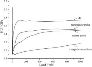
When applied dc current the fine grained and compact surface is observed. When square and rectangular current pulse are applied leading to rough surface with crack or crevices. When the triangular pulse are applied deposition made of grain conglomerates, a cauliflower like appearance and decreasing considerably compactness.
Figure 2‑4 Universal microhardness profile of the copper films obtained with different current programs
When applied dc current the plastic component show the hardest deposit is much coarser grain and less compactness than the applied triangular pulse current which gave softness and compactness.
Figure 2‑5 Plot of the plastic component of the microhardness vs. E for the copper films obtained with different current programs
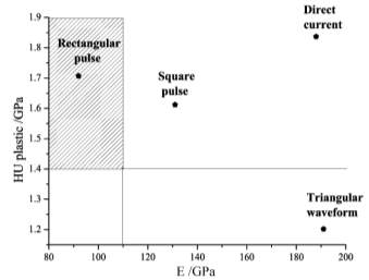
Increasing current density produce a decreasing in grain size and therefore increment in hardness. The hall-petch effect that established a linear dependency of hardness with reciprocal square root of grain size.
2.6 Influence of complexing agents on texture of copper plating
Influence of complexing agents on texture formation ofelectrodeposited copper [11]
Bo Hong, Chuan-hai Jiang, Xin-jian Wang
The electrodeposition of the copper is extensive used in industrial for conductive purpose.so the copper deposition very cheaper process than the vacuum deposition and chemical vapor deposition. The texture of copper deposited film mainly depends on the current density, the pH value of the solution, the temperature and the plating bath composition. There is necessary to distinguish two different texture for experiment one is based on no additive and another one is based on Ethylenediaminetetraacetic acid (EDTA) and sodium citrate as complexing complexing agents.
The experiment carried on initial electroplating with less thickness of copper coating 1 micrometer or less with no additive electrolyte solution after that thickness will be increasing gradually. The texture of electroplating may be substrate may change during the further growth process in thickness of the deposit owing to a gradual decrease of such influence in electroplating process certain complexing agent add in bath to lead to improve the properties of coating Structure modifies change in the structure of the deposit and even the preferred orientation.
EDTA and sodium citrate were added to the common formulation bath CuSO4 + H2SO4. The evolutions of texture in the films were investigated with X-ray diffraction (XRD) analysis. The substrate was an amorphous Ni–P alloy prepared for electroplating submerged in EDTA and sodium citrate with distilled water. The experiment was carried out at room temperature at a current density of 4 Adm-2. X-ray diffraction technique was used to investigate the texture of copper film.
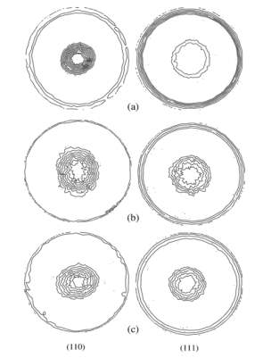 Here the fig showing the copper coating on electrode with additives and without additives. The texture of copper deposited influence on crystalline structure of the substrate. The experiment could be work of formation of the critical 2D and 3D.the substrate on which coated has been done influence due to internal surface and there is FCC nuclei structure. When the electroplating in initial surface there is less work of formation due to 3D nuclei. After some time thickness will increasing their take place 2D due to not influence on substrate surfaces.
Figure 2‑6 (110) and (111) pole figures of electrodeposited copper film. (a) Without additives, (b) with sodium citrate, and (c) with EDTA
The graph shown the copper deposited in without additive is higher texture coefficient than the other additives which were only enhanced the thickness of coating. There is texture change from one state to state 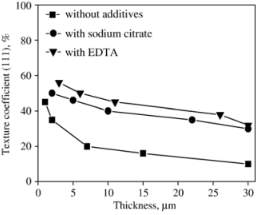 to increasing thickness of deposited copper due to work on formation change the orientation of texture crystallize form. The texture coefficient given by an equation.
TC(hkl)=I(hkl)Io(hkl)1nΣI(hkl)I(hkl)
Chapter: 3. Electroplating apparatus
3.1 Existing electroplating setup
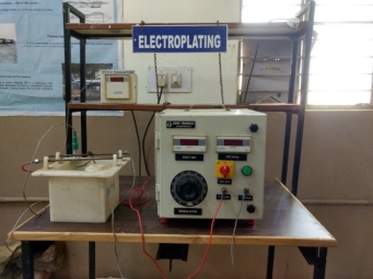
The electroplating machine in the laboratory is a small-scale apparatus for plating small components. The circuit consists of a rectifier circuit for converting AC Power supply to DC. The rectifier has a range of output voltage of 0-6V and maximum current rating of 10A. The positive terminal of the DC output is connected to the anode electrode and the negative terminal is connected to the cathode electrode.
The rectifier circuit has an Ammeter and voltmeter with resolution of 0.01A and 0.01V respectively. The voltage between the outputs can be controlled by the auto-transformer knob. The current flow changes accordingly with the change in voltage.
It has a polypropylene tank with fixtures for holding the electrodes as bath. The dimensions of the PP tank is 15X15X15 cm. The component to be plated is dipped in the electrolyte with connection from cathode.
3.2 Upgradation with automatic cut-off circuit.
The electroplating apparatus was upgraded with an additional cut-off circuit that cuts off the current supply for plating after desired time. The automatic cut-off circuit is a micro controller based electronic circuit that is added between the terminals of the electrode to connect and disconnect the power supply.
3.2.1 Construction of the cutoff-circuit
Following components are used for making the cut-off circuit
- Arduino UNO R3 microcontroller
- Jumper cables
- PCB
- Liquid Crystal Display
- Potentiometer
- Buzzer
- Switch
- Relay
- keypad
3.2.2 Bill of materials
The bill of materials for preparation of the cut-off circuit is shown in the table below
| Description of material | Quantity | Total amount (₹) |
| Arduino UNO R3 microcontroller | 1 | 530 |
| Jumper Cable | 20 | 80 |
| Copper plated board | 8cm x 6cm | 50 |
| Liquid Crystal Display | 1 | 250 |
| Potentiometer | 1 | 10 |
| Buzzer | 1 | 30 |
| Ferric Chloride | 500 gram | 180 |
3.3 Circuit diagram
The cut-off circuit is made by wiring the Arduino microcontroller with the peripherals and then programming it to control the power supply. The peripheral components include keypad, buzzer, LCD screen and relay. The keypad is used to provide input to the micro-controller. The Buzzer and LCD display acts as output interfaces and the relay is the actuating device.
The peripherals are connected to the specified Arduino board I/O pins for input and output signals. A list of I/O pins to which each of the peripheral is connected is listed below.
The schematic of the Arduino UNO board referred here can be used to identify the connection pins used below. [12]
Table 3‑2 Peripherals with I/O pins connection
| Component | I/O pins used on Arduino |
| Keypad | 2, 3, 4, 5, A0, A1, A2, A3 |
| LCD screen | 6, 7, 8, 9, 10, 11 |
| Buzzer | 13, GND |
| Relay | 12, GND |
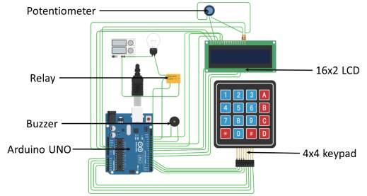
The circuit diagram of the cutoff circuit is shown with jumper cables connecting the Arduino board and the other components. The light bulb is a representation for the electroplating apparatus, indicative of a power-consuming component.
3.3.1 Description of the Micro-controller board and Peripheral components.
Arduino Uno : Arduino Uno is the ATmega328p microcontroller based development board and have 14 digital output pin in which 6 pins provide PWM output, Analog input pins are 6, operating voltage 5V, used for controlling the connected peripherals.
Keypad : Keypad used is 4×4 matrix type has 8 pins 4 for raw and 4 for Colum.
Buzzer : Buzzer used is of 5V rating, to alert the operator when the plating is over.
LCD screen : LCD is used is 16×2 type, which is capable to show alphanumeric digits, with variable brightness control.
Relay : Single channel relay is used to cut off the circuit, Supply volt for the relay is 5V, and the current Ratings are 10A at 250V AC and 10A at 30V DC.
PCB : single side copper plated board is used to make the PCB, which will act as the Arduino Shield.
3.3.2 Simulation of the circuit.
After finalizing the Arduino board and the peripheral components required for cut-off circuit. A circuit diagram was made and simulated on an online simulator, Autodesk123D. The circuit was refined and modified with minor changes and then the connections were finalized.
The simulation was done by connecting all the components to the Arduino board. The controller was programmed with actual program written for signaling the specific pins for each component mentioned above.
After successful execution of all the functions of the circuit components was achieved the program and the circuit was finalized. The simulation of the cut-off circuit can be seen in the video below.
3.4 Final setup with the cut-off circuit
A prototype of the circuit was prepared after simulation with all the components attached to the programmed Arduino board. For attaching the circuit to the Electroplating apparatus the prototype was refined to be able to fit in a box for easy attachment.
3.4.1 Manufacturing the PCB
The connecting wires of the peripheral components were replaced by a Printed circuit board that acts as an Arduino shield. The PCB was printed by tonner transfer and etching method. The pathways of the PCB were designed in the Autodesk Eagle software such that cross over of the paths is avoided.
The end points of the paths have soldered terminals that go directly into the Arduino pins. The entire circuit was then reconnected to the PCB and fitted into a box with only the interface components outside.
3.4.2 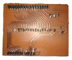
Connections with the apparatus
The Cut-off circuit is placed in between the positive terminal of the electroplating apparatus. The positive terminal of the rectifier is connected to the input terminal of the cut-off circuit relay and the output is connected to the anode. A bypass switch is placed between the two terminals to bypass the cut-off circuit and supply power directly to the electrodes. This bypass switch becomes helpful if the apparatus is to be used normally.
Chapter: 4. Experimental Analysis
The experimental analysis of the electroplating was divided into two parts one was for the process evaluation of the MSG bath compared to pure copper sulphate baths and the other was for reliability testing of the cut-off circuit in achieving the required deposition.
4.1 Evaluation of the MSG bath
First trial of deposition of Copper from baths based on the glutamate ions was investigated as using cathodic polarization, cyclic voltammetry, X-ray diffraction. [6] In this study compact and highly adherent deposit of Copper was obtained.
Here the evaluation of a Copper Sulphate bath with MSG as an additive was carried out at different concentrations of Copper Sulphate solutions.
4.1.1 Preparation of electrolytes
The solutions prepared for the experimentation were 0.1M , 0.2 M and 0.5M CuSO4.5H2O with 0.1M MSG. Distilled water was used for preparation of the solutions in which crystals of extra-pure copper(II) sulphate and Mono-sodium Glutamate were added to achieve different concentrations.
4.1.2 Preparation of cathode samples
The samples to be used as cathode for plating are made of 75x25x3 mm SS304 plates. A hole is drilled in each of these samples to conveniently hold it by an alligator clip while dipping in the electrolyte. The plates were cut and grinded to approximately same dimensions in pairs of two. The plates were then sanded by a sand paper of Grit 150 to achieve nearly exact weights to measure the deposition of copper accurately after deposition. One of the two plates in each pair were used for electroplating in pure copper sulphate solution and the other was used for a solution with MSG as additive.
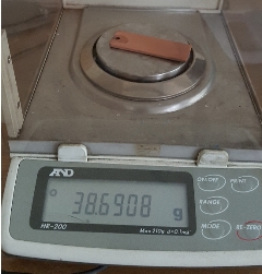
4.1.3 Experimental evaluation
The samples were plated for 20 minutes in Copper sulphate baths free from MSG and then with MSG. The difference in weights of the samples before and after plating were calculated to find the amount of copper deposited on its surface. The weights were measured by a highly accurate laboratory weighing scale HR-200 with maximum capacity of 210g and resolution of 0.1mg. The results of the evaluation are tabulated below.
| Pure copper Sulphate | Copper Sulphate with MSG as additive | ||||||
| Concentration (M) | Initial Weight (g) | Final Weight (g) | Deposition (g) | Initial Weight (g) | Final Weight (g) | Deposition (g) | |
| 0.1 | 38.3403 | 38.4363 | 0.0960 | 38.3418 | 38.4418 | 0.1000 | |
| 0.2 | 38.5077 | 38.6908 | 0.1831 | 38.5090 | 38.7115 | 0.2025 | |
| 0.5 | 38.1189 | 38.3011 | 0.1822 | 38.1187 | 38.3291 | 0.2104 | |
4.1.4 Result and conclusion
The use of MSG as additive clearly shows an increase in deposition of copper over the plates. It indicates an increase in current efficiency. The deposits at lower current densities were smooth and evenly coated, But at higher current densities the deposition were spongy and seemed to be burnt. This effect was more seen near the edges and corners which might have higher local current densities.
4.2 Repeatability testing of the cut-off circuit
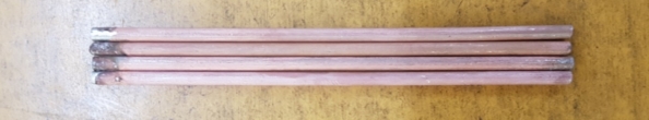
The Automatic cut-off circuit cuts off the power supply after a period of time entered by the user. The time is calculated by faraday’s laws to achieve desired deposition on cathode. It is important to test the reliability of the cut-off circuit in achieving the desired deposition every time. Electroplating of copper layer on steel wires for the applications like telephone cables and SAW electrodes. [13] High tensile Stainless steel wires have also been plated with a layer of copper as lubricant for drawing. [14]
4.2.1 Methodology of the experiment
0.1 M CuSO4
∙5H2O electrolyte was prepared as per the procedure followed in the evaluation of MSG baths. The samples were prepared of the steel wires as required in the application. Steel wires of diameter 2.8mm were used. The wires were cut to equal lengths of 10 cm, and then grinded by using a rough file to exact equal weights of 5g each.
The wire samples were used as cathodes for electro-deposition of copper. Plating was done using the current and voltage set at 0.05A and 0.5 V respectively. The wire samples were then plated one by one with a timer of 20 minutes set on the cut-off circuit. The results were compared with the theoretical deposition that would be achieved in 20 minutes for the repeatability test. For the cut-off circuit to be repeatable in its performance it should produce same results again for all five test samples which must be in conformance with the theoretically calculated results.
4.2.2 Theoretical calculation by Faradays law.
The amount of copper that can be deposited on the wire samples can be calculated by the faraday’s law of electroplating. [3]
m=ZIT
Where,
Z=Electrochemical equivalent
I= Current, A
T= Time, S
Z=EF
Where
E=Atomic MassValency
F=96485 C
m=ρ.V
m=ρAt
Where
ρ=Density
A=Surface area
t=Thickness
A=πDL+π4D2
=95×2.8+(π4(2.8)2)
=841.82116758 mm2
=8.4182116758 mm2
Current=0.04 A
Current density= 0.048.41821=4.756039 mA/cm2
m=ZIT
=63.55×0.05×120096485×2
=0.01975 g
4.2.3 Experimental results
The practical values obtained in the repeatability test are as given below
| Initial weight (g) | Weight after plating (g) | Weight of copper deposited (g) |
| 4.9995 | 5.0164 | 0.0169 |
| 5.0008 | 5.0176 | 0.0160 |
| 5.0003 | 5.0176 | 0.0173 |
| 5.0003 | 5.0188 | 0.0185 |
| 5.0000 | 5.0172 | 0.0172 |
| Average deposition | 0.0171 | |
The standard deviation of the weight of copper deposition is = 0.0008
Hence the coefficient of variance in 0.0008/0.0171 = 0.047
4.3 Bill of materials used for experimental evaluation
Table 4‑3 Bill of materials for experiment
| Description of materials | Quantity | Total Amount (₹) |
| Copper(II) Sulphate | 500 gram | 425 |
| Mono-Sodium Glutamate | 100 gram | 130 |
| Alligator clips | 6 | 50 |
| Terminal | 2 | 20 |
| SS304 Electrode | 1 m | 70 |
| Pure Copper Electrode | 2’ | 150 |
| Distilled water | 10L | 30 |
4.4 Results and conclusion
The repeatability test of the cut off circuit indicates the coefficient of variance to be 0.047. So we can conclude the weight of copper deposition lies within 4.7% of the mean value. The cut-off circuit gives repeatable results within a range of nearly 5% under same test conditions.
Chapter: 5. Future Scope.
The demand for sustainable products and processes is growing. The plating industry produces large quantities of depleted electrodes, chemical effluents and other waste. The composition of electrolyte is of great importance for achieving desired plating characteristics. In case of Copper plating baths with acidic and cyanide compositions are used that pose a challenge in handling and disposal of waste. Since the last half century more than 100 additives have been patented for use in Copper plating. [3] Mono-sodium glutamate is a fairly recent entrant, it is flavoring agent used in food. Its use as an additive is not yet fully evaluated. It is nontoxic, non-polluting and also gives better current efficiencies which is required to make electroplating process more sustainable. [6]
The automation of electroplating setup is a step to modernize the electroplating process with controlling the parameters affecting electroplating. While the present cut-off circuit controls the time of electrodeposition. Other attachments that can dynamically monitor and alter parameters like current, voltage, temperature and concentration can be developed and applied in unision for any setup.
Chapter: 6. References
| [1] | W. Sha, X. Wu and K. Keong, Electroless Copper and Nickel–Phosphorus Plating, Cambridge UK: Woodhead Publishing, 2011. |
| [2] | M. Paunovic and M. Schlesinger, Fundamentals of Electrochemical Deposition, Wiley Publishing, 2006, p. 373. |
| [3] | M. Schlesinger and M. Paunovic, Modern Electroplating, Wiley Publishing, 2014. |
| [4] | N. Mandich, “Cyanide copper plating reinvents itself: Workhorse system finds a niche despite declining demand in key markets,” Metal Finishing, vol. 103, no. 3, pp. 29-35, 2005. |
| [5] | United States Environmental Protection Agency, “Capsule Report: Managing Cyanide in Metal Finishing,” National Service Center for Environmental Publications (NSCEP), 1999. |
| [6] | M. Ibrahim and R. Bakdash, “New non-cyanide acidic copper electroplating bath based on glutamate complexing agent,” Surface and Coatings Technology, vol. 282, pp. 139-148, 2015. |
| [7] | S. A. E. Rehim, S. Sayyah and M. E. Deeb, “Electroplating of copper films on steel substrates from acidic gluconate baths,” Applied Surface Science, vol. 165, no. 4, pp. 249-254, 2000. |
| [8] | O. akır, H.Temel and M.Kiyak, “Chemical etching of Cu-ETP copper,” Journal of Materials Processing Technology, Vols. 162-163, pp. 275-279, 2005. |
| [9] | Z. A. Hamid and A. A. Aal, “New environmentally friendly noncyanide alkaline electrolyte for copper electroplating,” Surface and Coatings Technology, vol. 203, no. 10–11, pp. 1360-1365, 2009. |
| [10] | A. Ibañez and E. Fatás, “Mechanical and structural properties of electrodeposited copper and their relation with the electrodeposition parameters,” Surface and Coatings Technology, vol. 191, no. 1, pp. 7-16, 2005. |
| [11] | B. Hong, C.-h. Jiang and X.-j. Wang, “Influence of complexing agents on texture formation of electrodeposited copper,” Surface and Coatings Technology, vol. 201, no. 16–17, pp. 7449-7452, 2007. |
| [12] | Arduino inc., “Arduino,” Arduino, [Online]. Available: https://www.arduino.cc/en/uploads/Main/arduino-uno-schematic.pdf. [Accessed 2017]. |
| [13] | G. N. K. R. BAPU, J. AYYAPPARAJU and G. DEVARAJ, “CONTINUOUS COPPER PLATING OF STEEL WIRES,” Bulletin ofElectrochemistry, Vols. 7-8, no. 15, pp. 248-251, 1999. |
| [14] | D. E. Carleton, “Electroplating stainless steel”. Patent US2293810 A, 25 August 1942. |
Cite This Work
To export a reference to this article please select a referencing stye below:
Related Services
View all


Related Content
All TagsContent relating to: "Electronics"
Electronics regards the science and technology involved in the development of electrical circuits and electronic devices and equipment that use them.
Related Articles

DMCA / Removal Request
If you are the original writer of this dissertation and no longer wish to have your work published on the UKDiss.com website then please: