Android System Application to Obtain Information from Vehicles On-Board Diagnostics
Info: 16919 words (68 pages) Dissertation
Published: 11th Dec 2019
Developing Android System application to Obtain Information from Vehicles On-Board Diagnostics using Bluetooth Protocol Network Connectivity
Contents
Research and Literature review
Assessment of Development Software
Existing OBD Applications on the market currently
Assessing my application against Existing Applications
How the ECU communicates with OBD Hardware
Software used for Implementation
Application Testing and Result Analysis
Limitations and Future Improvements
“My Simple OBD Application” limitations
Real-time data Analysis Limitations
Abstract
The aim of the project is to develop a free android based OBD Application implementing the Bluetooth network protocol connectivity that enables inspection of a vehicles DTC faults. Through obtaining the DTC codes stored in the Engine Control Unit (ECU) by means of connecting an android application using the Bluetooth communication protocols to a Bluetooth enabled On-Board Diagnostics kit (OBD). If a DTC code is obtained during communication between the two Bluetooth devices, the android application allows removal of the DTC code.
Introduction
Background
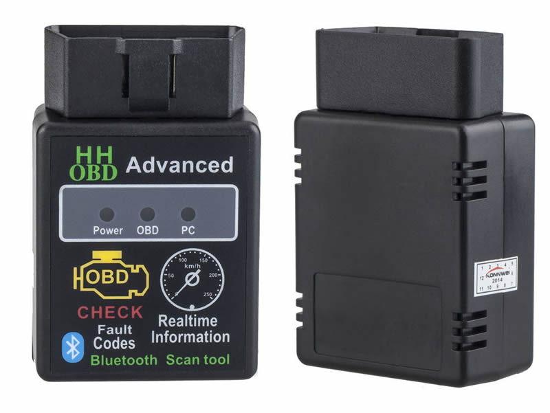
Many people have to pay a fee of around £30-£60 to a mechanic or download an Android vehicle diagnostic application costing £10-£15 along with an OBD (On-board Diagnostics) reader, to be able to attain meanings of the DTC’s (Diagnostic Trouble Code). The purpose of the project is to design and build a free Android Bluetooth network enabled application that successfully communicates and transfers data to a Bluetooth enabled OBD reader, for the purpose of the report an ELM327 was purchased and used as the OBD reader to attain the DTC meanings.
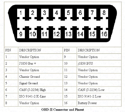
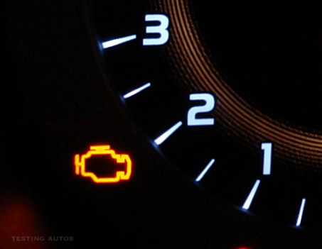
The majority of modern cars are all controlled by an Engine Control Unit commonly known as ECU. The ECU controls the vehicles engine functions by obtaining values from various sensors e.g. the camshaft sensor, exhaust emissions sensor, and many others. If there is any major issue with any of the sensors the MIL (Malfunction Indication Lamp) located on the instrument cluster (See Appendices A) will illuminate indicating to the owner there is an issue with the vehicle. The data is processed to diagnose any problems the sensors obtain, which can help identify vehicle problems. All modern cars also contains a 16-pin Data-Link-Connector (DLC) which is known as the OBD port (See Appendices B). The port is designed to enable the user to connect the Diagnostics kit, such as the OBD reader. Once the issues fixed the code should be cleared, this will allow the MIL to turn off.
OBD System was designed to monitor how the vehicle performs while also controlling emissions. Depending on the pins available in the OBD port determines what protocol the vehicle uses for its communication (See Appendices C).
Research Methodology
New knowledge and information that had to be acquired in order to build and test an Android Application. Numerous databases and sources of information were accessed for this Project. The following databases, and search terms that were searched to obtain knowledge and information are listed below:-
Databases
- Using the university intranet to search for suitable books and articles contained within the University of Hertfordshire library.
- Elsevier
- University of Hertfordshire Intranet to search for articles located in other university institutions
- Google Scholar
- Google search Engine
Search Terms Used
- Android
- Android Plays store
- Java
- Programming
- OBD applications
- Android Manifest
- Bluetooth Network Connectivity
- Wi-Fi Network Connectivity
- NFC
- Network Connectivity
- Android Manifest
- Android programming for beginners
The above databases and search terms yielded a vast amount of knowledge and information. The most relevant data was gathered, stored, analysed. All non-relevant literature and information was disregarded. The information was processed into data sources types, all relevant website information was stored into a Folder labelled Website information. Further subsection Folders were also created within Website information and labelled, such as Android Developer website and GitHub website. This Method was also implemented in other data source types e.g. Articles, Books, and Online Videos.
Objectives
The main objectives of the project are listed in the Objectives table (Table 1) below and must be implemented correctly for the aroid application to function properly. The desirable objectives have also been considered, they are implemented for the purpose of making the application to be more productive and user friendly.
| Main Objective | Comments |
| Successfully connect two Bluetooth devices | This is successfully achieved by connected the mobile application to the elm327 Device |
| Successfully transfer data between devices | This is also successfully achieved as the trouble codes are received from the ECU |
| Successfully work of android devices | This objective has also been achieved as the application works on a Samsung s6, a HTC m8 and a LG G5 |
| Allow application to be able to retrieve Vehicle Fault Codes | This objective has also been achieved as fault codes are displayed on the screen by the application |
| Allow user to obtain any type of information they want | This has not been achieved, although the user can input any Parameter ID the information is not displayed the correct way |
| Allow user to be able clear error codes | This has also been achieved as for the benefit of the test a faulty vehicle was used and the codes were cleared once the “remove” button was pressed. |
Objectives(Table1)
| Desirable Objective | Comments (At end of project) |
|
Not completed due to Time constraints and knowledge limitations |
|
Implemented as shown is Usability Test |
|
Not implemented due to Time constraints and knowledge limitations |
Report structure
This section of the report will show how the rest of the report is organised, in stage 2 of the report, will detail background research conducted and the issues worked on within the project. The information observed is essential to read and understand to comprehend the sections that follow. Contained within section is the additional research that was conducted. Stage 3 details the thought-out plan of the design along with design layouts. Stage 4 contains details of the implementation phase, within this section it details, what steps were taken to achieve the end goal. Section 5 consists of the Testing phase, detailing how testing was conducted, what types of test cases were performed along with the test results. The Final stage contains details of the analysation phase, which describes the difficulties that were encountered as the project progressed, in addition to how they were overcome and the limitations faced. This section furthermore contains further improvements that could have been implemented including future work that can be conducted. The final sub section within the final stage of the project giving the conclusion of the report along with detailed description of the learning curve achieved
Insert Gantt chart
Research and Literature review
Literature Review
There are number of studies available in the literature on the study of the OBD system, several applications have been built for use on mobile phones using the Android platform to provide various services.
When focusing specifically on the OBD applications developed for diagnosis of DTC fault codes using mobile phones, very few works are available.
The study done by Tahat et al., (2012), Ganapati et al. (2014), Kene and Khisti,(2014), and Nille et al., 2015)are identical prior projects to each other and that of Kumar, T. and Sivaji, S. (2015). These projects however does not connect to a vehicles in built Liquid crystal display like that of Kumar, T. and Sivaji, S. (2015) who created a system to provide a low-cost means of monitoring a vehicle’s performance and tracking by communicating the obtained data to a mobile Android device. By means of a hardware device built to interface between the vehicle’s on-board liquid crystal display and a Bluetooth module which communicates with an Android device. The results can be viewed on the application developed by the authors to monitor Temperature, Humidity and Fuel consumption. The application is further capable of transmitting data to a server using cellular internet connection.
Another project designed and developed by V.Malpani, S. et al (2015) is similar to that of the projects above. A purpose built hardware unit with Bluetooth connectivity is built for the purposes of relaying data to a mobile Android device. In this project two android applications were developed. One application for measuring vehicle data e.g. oil level and engine temperature, the other application utilising android GPS to display if the vehicle is exceeding the speed limit similarly the project of Al-taee et al (2007) Warns the driver in the event that a vehicle exceeds the speeding limit a designated sound and text prompting occurs(G.F.Turker, 2016)
Y.Yang et al (2015) proposed a system using a Bluetooth OBD II reader for acquiring real time vehicle parameters from the CAN bus of a hybrid electrical vehicle. The OBD II reader used the ELM 327 integrated chip to interpret the CAN protocol. The data was received wirelessly by an Android mobile device over a Bluetooth network. The data could also be sent via GPRS to a remote server from the android mobile device.
J. Zaldivar et al(2011) developed an Android-based application that monitored the vehicle via an OBD II interface. They measured various parameters for example measuring the air-bag trigger and G-force experienced by the passenger during a collision in order to detect accidents. In the event of a collision the data could be sent to emergency services and any other persons desired.
It is observed from the studies above that real time vehicle parameters can be measured, however there is a limitation in the parameters measurable using standard PIDs defined by OBD II. Fuel consumption does not have standard PIDs, this parameter will have to be computed from parameters such as mass air flow and speed. (Malekian et al., 2017)
History of Android
Primarily being a venture of Four men, Android Inc. was created in 2003, for the purpose of constructing an advanced Digital Camera Operating system, as development progressed it became obvious the original target was too restrictive. The team started to focus on a system to compete with Symbian Operating system which at the time was used on PDAs and early smartphones. In 2005 Google, had brought the company while keeping the original team on, with the help of Google the Android operating system went on to become one of the most commonly used operating system for major phone manufactures such as Samsung, HTC and Sony consuming over 80% of the mobile market.
The Android operating system is developed on the Linux kernel system which uses C as its main programming language. The C programming language was one the first Programming languages that was created for programmers using simple syntax, making it an easy to use language. To date it is still one of the most powerful programming languages as it has developed and evolved. (Fresh2refresh.com, 2017) In recent times Android has moved on to use Java programming language, a derivative form of the C programming language. The major difference between the two is that the Java language is more Object Orientated programming whereas the C programming language is a procedure orientated programming Language. (Dev, 2010)
Assessment of Development Software
When creating the application, there were many different types of Software Development Applications available in order to design and build the Android application (Jr., 2015). The Software Development Application chosen to create the application was Android Studio. The reason this was chosen is because the vast amount of resources that are available for Developers of Android Applications from the official Android website as well as other sources. The alternative Software Development Applications that were considered, consist of the following in the table below table 2;
| Software | |||||
| Features | PhoneGap
(See Fig 2) |
Corona SDK
(See Fig 3) |
Android Studio
(See Fig 4) |
Eclipse
(See Fig 5) |
NetBeans
(See Fig 6) |
| Built in emulators |
|
|
|
||
| Code correction help |
|
|
|
|
|
| GUI View |
|
|
|
|
|
| Built in Text Editor |
|
|
|
||
| Help and support |
|
|
|
|
|
| Built-in Tips and pointers |
|
|
|
||
Table 2(Assessment of development software)
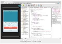
Figure 1 : PhoneGap |
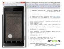
Figure 2: Corona SDK |
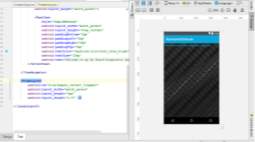
Figure 3:Android Studio |
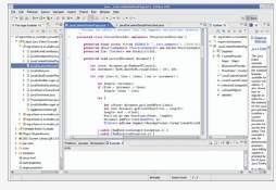
Figure 4: Eclipse |
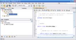
Figure 5: NetBeans |
Two key Features that are consistent through-out the list of possible software that can be used are help and support and help with code correction although with Phone Gap(see Fig 2) and Corona SDK (see fig 3) the user must download additional software add-ons to help with Code correction. Another disadvantage of these two Software Development Applications possess is that the Developer must download an additional text editor which must be compatible with the Software (labs, 2017), (phonegap, 2017) . The main difference Phone gap has compared to the other four applications is it does not support built in tips and support the user will need to have access to the internet and obtain help from forums or the phone gap website.
Eclipse is another software that was considered when creating the Android Application.(See fig 5) Before Android Studio was released Eclipse was the main Application Development Software employed to help Developers create Android based applications. Eclipse is a basic development software with a huge library of available plug-ins that cover a vast amount of development requirements. Although due to the requirements of the plug-ins the software consumes a vast amount of computer resources. This meant the user would require a high specification powerful computer in order to maintain multiple applications running(Paraz, 2015), (Binstock, 2010), (Nille et al., 2015)
NetBeans was additionally considered(See Fig 6). This is because it has an easy to use interface, that even a novice is capable of using it effortlessly. Similar to Eclipse, NetBeans also has a library of plug-ins to help aid the developer with the programming however it is not as immense as the one available to Eclipse developers. Although there are some features which are available on the NetBeans software that come as a package when the user downloads the software, the features are built in support giving Developers help with tips and support. Furthermore it provides the user with a GUI view which helps the developer visualise how their application will appear. One feature which is not available on NetBeans or Eclipse software is the use of an emulator, this feature is critical when creating the application as it would allow the developer see how the application would function on a mobile phone (Katamreddy, 2014), (Nille et al., 2015)
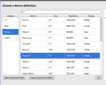
Android studio was the software considered to be the most beneficial when creating the application for this project (See Fig 4). There were several key reason Android studio was chosen as the Development Software application to develop the Android Application (Wayner, 2013). The first reason was it is simple to use, and as a first-time user the software gives pointers and helpful tips to the developer. Developers also benefit from an immense library of support, which includes helping users with basic snippets of code (See Appendices D). Another factor why this software was chosen is due to the emulator, as it provides a realistic simulator of a mobile phone of the developer’s choice. Consisting of a large library of possible mobile phones from the HTC one to the Samsung Galaxy S6 (Emulator, R. 2017),(See Appendices E).
Another key reason Android Studio was the chosen Development Application Software, was due to the types of testing the developer can achieve throughout the build process of the Android Application. There are a few types of basic testing Android Studio supports such as Espresso Test Recorder and Command Line Testing. Espresso Testing is a tool that allows developers to test the User Interface (UI) thoroughly, this is achieved by the developer creating specific tests and then monitoring the developer’s interactions and adds statements that help verify the UI elements (Recorder, C. 2017). Command line Testing acknowledges developers code specific tests for example, this type of testing will allow the user to test specific types of classes, methods and functions within the application (Line, T. 2017).
Existing OBD Applications on the market currently
There are several applications that are currently available on the Android platform from the Play Store, that perform similar functions as the intended solution that is proposed in this report. Some of the Existing applications and their features are listed in the table below along with benefits and drawbacks.
| Applications | |||||
| Features | Torque
(See Fig 7) |
Vehicle Doctor (See Fig 8) | Smart Control(See Fig 9) | Piston (See Fig 10) | My simple OBD Application
(See Fig 11) |
| Customisation of Application |
|
||||
| Auto Connectivity |
|
|
|
|
|
| Real time data Display |
|
|
|
|
|
| Bluetooth Connectivity |
|
|
|
|
|
| Wi-Fi Connectivity |
|
|
|||
| Save data to device |
|
|
|
||
| Location Logging |
|
|
|
||
Comparison of Existing Applications (Table 3)
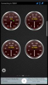
Figure 6:Torque |
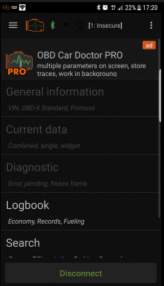
Figure 7: OBD Car Doctor |
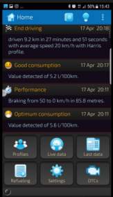
Figure 8: Smart control |
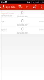
Figure 9: Piston |
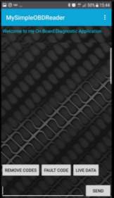
Figure 10:My Simple OBD Reader |
When comparing exiting applications that are currently on the market today, there were three key features that are consistent throughout all 4 of the applications compared and contrasted. These consisted of displaying real time data, allowing Bluetooth Connectivity and displaying DTC codes (Goodwin, 2012) .These are considered to be main functionalities of the applications and make them a success on the Google Play Market. Therefore the three features have also tried to be implemented with the “My Simple OBD Reader” Application.
The Torque Application is the only one out of the four applications, that offers the user to be able to customise the application to suit their needs allowing them to place specific gauges and widgets to show data that the user wishes. The Torque application also enables the user to choose specific themes and colours giving the application that personal touch. However compared to the other three applications, the Torque application lacks in a few key factors that are beneficial to the user but not necessities, these consist of saving data to the device and location logging. Saving data to the device can be beneficial to the user as it can allow the user to analyse the vehicle behaviour, seeing what DTC codes are frequent with the vehicle, along with being able to reflect on the driving skills of the user by analysing the real-time data. Location logging could also be beneficial to the user, this feature can enable the user to track how far have travelled analysing the amount of fuel consumed within that route, another major factor for the location logging is if the user was to obtain any false accusations regarding the whereabouts of his vehicle such as obtaining a false fine. The user can provide evidence stating his innocence.
Three of the four applications above have implemented an auto-connectivity feature, this would enable the application to connect to the ELM327 device (See Appendices F) as soon as the application is started. Piston being the only application not to implement this feature, although this is mainly implemented to help improve the usability of the application, and is not a considered to be a key feature. Although auto-connectivity has not been enabled by Piston, it has chosen to implement Wi-Fi connectivity like the Torque application, the only two to do so out of the four. Two of the applications have implemented identical features suggesting these features are crucial for a successful vehicle analysis application.
All applications mentioned above were downloaded and thoroughly tested to find any differences and similarities. Table two stated above, shows the results of tests looking for key functionalities and features.
Assessing my application against Existing Applications
After analysing the existing application, some of the features implemented where considered to improve applications usability and increase the audience base, one of these features was to be able to display real-time data. Displaying these features in the “My Simple OBD Application” would benefit the user greatly as some of the real-time data given to the user consist of Mass Air Flow (MAF), Fuel-Consumption and many more real-time data sets. With this information the user can establish how much the fuel the motor vehicle consumes.
Some Features which were available within existing applications on the Play Store that are not present in “My Simple OBD Application” consist of, being able to connect through the mobile phones Wi-Fi network. The reason this was not implemented in this “My Simple OBD Application” was due to the fact that Wi-Fi is a greater drain on the battery of the mobile phone than Bluetooth network. The user of the “My Simple OBD Application” will be using the application and the OBD device in close proximity therefore Bluetooth is more than suitable for this type of distance.
Location tracking feature was not included in the scope of the project, although there are benefits for this feature. A disadvantage of Location Tracking is Privacy concerns some users find it a breach of a person’s private freedoms and information if an application can track their location, even if the feature is for beneficial purposes. This concern of the users can deter them for downloading the application from the Play Store, as stated on the Android Developer Website
Type of Network Connections
When building the “My Simple OBD Application” several aspects as to how Bluetooth connectivity functions and how it is implemented were researched. The research element of this consisted of considering, what is the key technical and programming aspects of the client side and server side. Researching how to implement and manage the Bluetooth Socket once a successful connection had been established between the two Bluetooth enable devices.
Bluetooth Network
Bluetooth is a type of network communication protocol which is designed to connect devices using a low bandwidth over a short range, it is used for peer-to-peer communication. Bluetooth accomplishes the communications connection by using the Bluetooth Sockets. For a successful connection, there will need to be two types of connections. First being the Client side for one device and along with that there needs to be a Server side connection with the other device, this will permit the application transmit and receive data (Developer.android.com. (2017).
Client Side
The client side aspect of the connection consists of the application initiating a connection with the remote device, the remote device must be accepting connections and have an open server socket to connect to the client. The client side is the one making a connection to retrieve information and send commands from and to the OBD device. For the client side to create a connection it must first obtain the Bluetooth Device object which represents the device it wishes to connect to, then it requires the Bluetooth socket to initiate the connection (Developer.android.com. 2017).
Server Side
The Server Side aspect of the connection acts as the server by having an open Bluetooth server socket, this is so it listens for any requests for incoming connections. Once the Bluetooth module accepts the request, the server side provides a connected Bluetooth Socket once the two devices have connected, and the Bluetooth Socket is initiated. the Bluetooth server socket would then normally be discarded unless more connections are required.
Security Risks
Like any type of network connection there is constantly a threat to the security of the data being transferred, and possible damage to the devices that are communicating with each other. Some attacks that can be implemented to a Bluetooth Network Connection consist of,
- Eavesdropping – When the attacker listens to the mobile devices phone calls and retrieve data from the phone. (Jennings, 2017)
- Denial of Service – when the attacker crashes the user mobile device, preventing them from receiving calls and reducing the battery life of the device. (Jennings, 2017))
- Bluesnarfing – When an attacker exploits Bluetooth connections to steal information from the targeted mobile device without the knowledge of the victim. (Lekowski, 2013)
- Worms and Virus – Similar to when a user is connected to the internet, worms and viruses can additionally be spread across a Bluetooth connection. (Lekowski, 2013)
The most proficient method to prevent any of the four attacks mentioned above, is to have the mobile devices Bluetooth turned off when not in use or to make the mobile device undiscoverable when it is not required. This will prevent many of the attacks from occurring thereby keeping the users data secure.
Evolution of Bluetooth
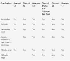
The technology (FHSS) that Bluetooth bases its communication protocol on was official patented in 1942 during World War 2, however in 1994 a communication company called Ericsson originally wanted to exchange the normal RS-232 cables (Blueapp, 2015) with a wireless structure. Working in partnership with some of the major communications companies (Nokia, Intel, IBM, and Toshiba) who had a similar idea to create a wireless communication for mobiles devices and desktop computers. Collaborating with each other, the companies where able to create a universal standard (Lugn, n.d.). Since 1994 there has been many Versions of Bluetooth, (See Appendices G)Each updated version has made a significant improvement from the previous version.
Bluetooth Low Energy
Bluetooth Low Energy (BLE) is the most recent improvement to Bluetooth, it is a more efficient version of the classical Bluetooth (See Appendices G) Network used in pLAN the basics of BLE is very similar to Bluetooth, however there are a few areas in which BLE is more beneficial for example the latency time is reduced from 10 milliseconds of the classical Bluetooth, to 6 milliseconds which the BLE achieves. Another beneficial of BLE is it has a reduced power consumption compared to classical Bluetooth. However these benefits do come at a cost, as the transfer speed is reduced dramatically. Classical Bluetooth can achieve speeds of 3mbit/s over a distance of 30ft, whereas BLE can only achieve a mere 1mbit/s over the same distance. (Anon., 2011)
Alternatives to Bluetooth
Bluetooth is categorized under the Personal Area Network (PAN), some of the alternatives that are also considered to be PANs are Infrared and NFC.
Infrared
Infrared wireless is an alternative as it can incorporate up to a 16 Mbit/s transfer speed however, this speed is not very fast and would give inaccurate readings of the real-time data that would be available on the “My Simple OBD Application”. Furthermore due to its limitations it wouldn’t be suitable to implement this for example, for the data to be transferred the transmitter and receiver need to be in sight of each other and no barrier between them. Another limitation consists of the infrared data unable to transfer through solid objects, amongst other limitations. (Gross, 2017).
Near Field Communication
Near Field Communication (NFC) is another alternative which is available on mobile devices and a feature that is supported by the Android developer website by providing APIs for its implementation in to an Android Application. NFC can achieve 424 Kbit/s transfer speeds compared to the 3mbit/s Bluetooth can achieve. Although the transfer speeds are slower on NFS however the connection is much quicker than Bluetooth as NFC does this automatically within a few seconds. However NFC is required to be within 5cm distance of the target device in order to communicate and transfer data. Thereby not making it a suitable feature for many applications including the “My Simple OBD Application”. (Liam, 2015).
Wi-Fi
Wi-Fi network connectivity is another method available to communicate between devices. This would fall under a Private Local Area Network (pLAN) rather than a Personal area network (PAN). Wi-Fi is one of the fastest wireless transfer type connections capable of transferring data up to a theoretical speed of 1GB/s. Wi-Fi can has the capability to connect multiple devices to the same network. With little degradation to data transfer speeds between devices when multiple devices are connected, this is due to WI-Fi’s high bandwidth capabilities. Compared to Bluetooth connected devices, the data transfer speeds decrease as multiple devices are connected. Bluetooth also has an inferior distance covering a mere 30ft while Wi-Fi covers a maximum distance of 105 ft (Frenzel, 2002).
How the ECU communicates with OBD Hardware
Protocols
The Leading vehicle manufactures all have specific protocols that allow their vehicles ECUs to communicate with the OBD. The protocols consist of;
| Protocol | Speed | Pins used |
| SAE J1850 VPW | 10.4 Kbps | 2,4,5,16 |
| SAE J1850 PWM | 41.6 Kbps | 2,4,5,10,16 |
| ISO 9141 | 10.4 kbps | 4,5,7,15,16 |
| ISO14230-4 | 1.2-10.4 Kbps | 4,5,7,15,16 |
| ISO15765-4(CAN BUS) | 500 Kbps | 4,5,6,14,16 |
Protocol (Table 4)
However since 2008 all vehicles have adapted to use the CAN protocols (ScanTool.net.Team., 2004). The protocol communicates between the ECU and the OBD reader, permitting information to transfer between the two devices.
Parameter IDs
For the OBD reader to use the data sent by the protocol and read the information, the device uses Parameter IDs (PID). The PID requests for specific types of data from the ECU for example, the Parameter ID 010C would show details of Revolutions Per Minute (RPM), the four Digit ID communicates with the OBD requesting specific information (Outilsobdfacile.com., 2017). The First two digits define the mode of the information and the last two digits call the ID of the information required. Mode 01 retrieves real-time data, and 0C is the ID associated with RPM values.(Full list of PIDS are available at Outilsobdfacile.com., 2017)
Diagnostic Trouble Codes
Once an error code is detected by the ECU the MIL illuminates. Once the user checks for an error code, it will be displayed as a 5-digit code which indicates to the user why the MIL is illuminated. The 5-digit code is split up by in to 4 sections. The first section advices on the type of error, the second digit states if the error is manufacture exclusive error, the third digit states what system the code refers to e.g. xx7xx would involve a transmission error. The final 2 digits (4, 5) refer to a specific failure code these range from xxx00 to xxx99 (Learn.sparkfun.com., 2017), (Outilsobdfacile.com., 2017).
Usability and Design
This section will detail how the application is supposed to function and visual representative of the application through the view of a Storyboard diagram. The section also contains how the “My Simple OBD Application” meets specific heuristics to provide the best usability features.
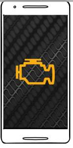
The primary function of the “My Simple OBD Application” is to allow potential user to be able to diagnose any issues their vehicle may have. Therefore when constructing the design there were a few features that were considered a must from the start. This consisted of a start-up screen which contains a consistent background image and an illuminated Malfunction Indication Lamp centred. This would be the Splash screen also known as the Welcome page of the “My Simple OBD Application”.
Usability Features
The International standards defines usability as “The extent to which a product can be used by specified users to achieve specified goals with effectiveness, efficiency and satisfaction in a specified context of use (usabilitynet, 2006).” Jakob Nielson came up with 10 general heuristics for user-interface design (see table 5), these 10 heuristics can also be applied when creating a mobile based application (Rodolfo Inostroza, 2013). When creating the “My Simple OBD Application”, these 10 heuristics were considered. Giving thought to how they could have been implemented to an “My Simple OBD Application”. The table below consist of the original 10 heuristics and how they can be implemented to a “My Simple OBD Application” (Lisa Kuparinen, 2013).
| Jakob Nielson’s 10 heuristics | How they can be used in Mobile applications |
|
The application will keep users informed through feedback within reasonable time |
|
The application will speak the familiar language to that of the user, with words, phrases and concepts, as a substitute system terminology. The information will be displayed in a logical way. |
|
The applications will allow the user to keep control over the application when interruptions such as phone calls and text messages occur. It will also allow user to stop any functions they accidentally do by pressing the back button. |
|
The application will remain consistent throughout all aspects and adhere to the platform conventions. |
|
The application has adhered to a careful design to help prevent any errors. If any errors still occur the user should be prompted with messages |
|
The main functions of the application are easily available. While minimizing the menu paths and keep main functions available always |
|
The application will flow effectively and efficiently through different screens. Furthermore, the applications user interface should be scalable for different screen sizes of mobile devices. |
|
The application dialogues will only contain relevant information and not bombard the user with irrelevant data. The application will similarly contain a vibrant distinction between the visual elements and colours. |
|
The application will show any errors in plain English, so it is easy for the user to understand and explain the problem as simple as possible. |
|
The application will provide guidance focused on the user’s tasks although due to the simplicity of the application documentation is not required. |
Ten Heuristics (Table 5)
Storyboard
When creating the application, one of the first processes was to design the applications outline and create a user-friendly sketch of the way the features would work. Using software called Balsamiq Mock-up, the storyboard underneath was designed as an indication to how the final application will appear and what it can achieve.
| Screen 1 | Screen 2 |
The First screen is a load up screen which will disappear after a few seconds. The launch screen will consist of a plain white background with the application name and an image Logo placed directly in the centre of the screen |
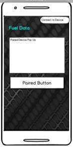
This page appears when the user clicks the menu button on the top right button which drops down a menu box containing three options the first option allows the user to connect to the OBD reader by accessing the users Bluetooth services and requesting devices that are paired to the devices already. The user can then select the OBD reader to make a connection to the device |
| Screen 3 | Screen 4 |
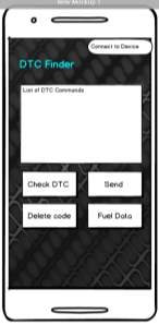
This is the main page of the application which contains four buttons at the bottom of the screen that the user can click on to make the application run specific functions one of the buttons will allow the user to request for any DTC codes. Correspondingly there is a button that will permit the user to remove these codes from the ECU, however if the issue is not resolved the MIL light will come back on. |
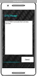
Once the user clicks on the “Send” button from screen 2 the application will communicate with the OBD reader allowing the user to send any data they wish to send. The data will then be displayed in a list format and show the user what they have sent. |
| Screen 5 | Screen 6 |
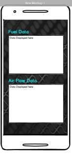
Once the user clicks on the “Fuel Consumption” button this page will show up authorising the user to view real-time data as the vehicle consumes the fuel. In addition to the Fuel data being displayed, this screen will show additional data such as the airflow Data. |
Class Diagram
In addition to a storyboard a Class diagram was created to demonstration how each page is linked to each other and how the system operates.
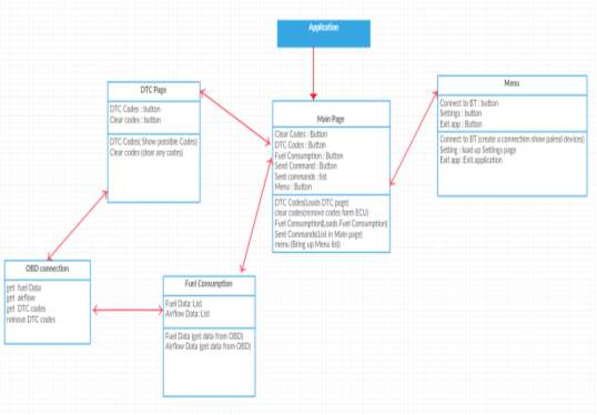
Figure 11:Class diagram
Implementation
Software used for Implementation
The first step taken to implement ‘My Simple OBD Reader’ was to find a suitable piece of software to help code this application and allow a visual representation that will allow the user to see how the layout of the application would be displayed on a device. During the research stage of the project, there were five key considerations for what software would be beneficial and most productive, each having key features that are required to make a successful application as mentioned in Table 3 (Comparison of Applications)
After thorough consideration, Android studio was chosen as the software to use. There were many reasons for this the main being Android studio provides a vast amount of knowledge via its developer website (Developer.android.com., 2017). helping with pivotal stages of the project such as providing basic implementation of Bluetooth communication. Another key reason Android Studio was used is because it is the main software used for android based applications, therefore there are many tutorials, blogs and videos to help with implementation phase.
Bluetooth Implementation
Connecting Bluetooth
The first step that is taken when coding the application is to be able to make a Bluetooth connection between the mobile device and the Bluetooth enabled OBD device. Android studio implements Bluetooth enabled permissions and provides a vast knowledge base that helped program this feature.
The first aspect of this implementation stage consisted of checking if the devices trying to connect to the OBD has Bluetooth capabilities. This is checked by getting the application to try and obtain the default Bluetooth Adapter if the devices states that it is Null this suggests that there is no Bluetooth adapter (see Fig 13 Bluetooth Adapter).
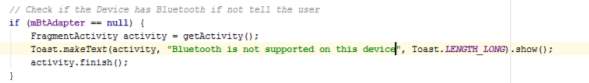
Figure 12: Bluetooth Adapter
Bluetooth Adapter (Fig 13)
The next stage is to check if the Bluetooth is enabled or disabled if the device is not enabled the application will bring up a notification asking the user to turn on their Bluetooth. This is achieved by enableing the application to send a requset to turn the Bluetooth Adapter on. 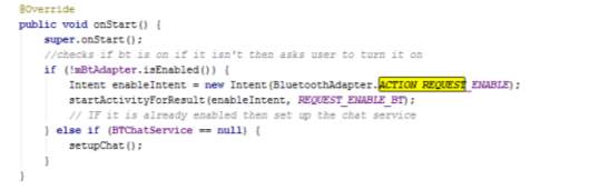 (Fig 14)
Figure 13:Enable Bluetooth
Enable Bluetooth (Fig 14)
Once the Bluetooth is enabled the next stage was to show the user devices that are already paried to the mobile device and allowing the to select a device they wish to connect to (see fig 15 Paired). Once the user selects the device it will then attempt to connect both those devices going through the connect section of the code (see Appendices H) and once this is successful it will go through the connected section and display to the user what device the connection has been made to(see Appendice I).
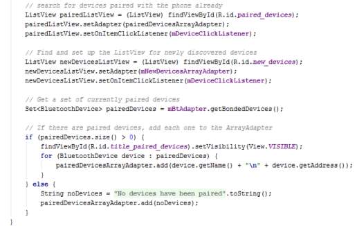
Figure 14: Paired Devices
Paired device(Fig 15)
When implementing this stage of the application, there were some errors that had appeared one of the main errors was a window leak this error occurred (see Fig 16) due to the fact the dialoge box for the paired device list was trying to close however the application was still trying to processs the dialog box this was over come by, implementing the DeviceListActivity class to show as a dialoge box instead of hard coding the dialoge box in the back end. To make the class show as a dialoge, android studio has bulit in-themes which can be applied to classes. This has to be done within the Android Manifest (see Fig 17). This would show the dialog box as intended while removing the error.
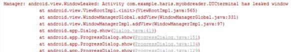
Figure 15:Leaked Window
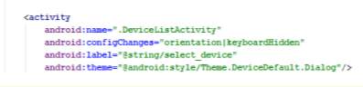
Figure 16:Dialog Theme
As the device is connecting, a set state phase was required. This is benifical as it permits both the user and application know what state the bluetooth is in, whether it is looking for a connection or conneted to a device (See Fig 18). Along with the set state there was a get state to help with further code. This section of code is pivital due to the fact this can be reffered back to when coding other features and using it within if statements for example;
if (mstate != STATE_CONNECTED){ do something } else { do something else}.
This means if the device is not connected then it will do something otherwise it will do a different function.
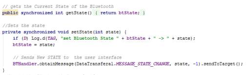
Figure 17:Set State
Communication
Once both devices are connected the next stage is to manage the connection this was achieved with three Key Threads that help maintain connectivity and manage the data coming in and going out.
The three threads consist of:
The Accept Thread
This thread is used to listen for incoming connections and accepts any Bluetooth Server Sockets trying to connect with the application for this to be accepted the UUID must match that of the one sent within connect thread. (see appendices J)
Within this section of the implementation another key error had occurred(see Fig 19), the error consisted of not being able to accept the thread to maintain the communication. This was due to the application being in a loop and trying to accept the thread more than once. Therefore, a cancel function was implemented once the application had accepted the thread it would move to the next section. 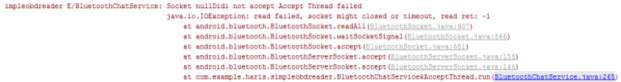
Figure 18:Accept Thread Error
The Connect Thread
The Connect Thread which acts as the client side connection with in the application. As per the research the client side is when the application initiates a connection to the OBD device, for this to be successful the OBD must accept the connection and contain an open server socket once the code accepts the socket it sets the UUID this identifies the application to the OBD device and continues to progress with the rest of the code. (see appendices K)
The Connected Thread
This thread is the main thread for communication in terms of data being sent and received the run functions is where the data that is incoming. It is then converted from bytes to a string that shows a readable text in the User interface. The write function is where data is written and then sent to the OBD reader. In keeping with the research this thread acts as a server side when communication is made. (see appendices L) The error below occurred during the read section of the code(See Fig 20). This error was due to the application trying to read the bytes after they have been converted to a string. The fault of the error was due to a human error as within the code instead of asking for the message read it was asking for the message byte. With making this small change the code started to work.
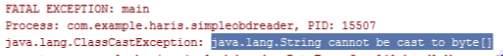
Figure 19:String Error
Design Implementation
When starting the project a storyboard was created this was used as a guideline for the implementation phase. Within this section it will discuss how the storyboard is implemented to the application.
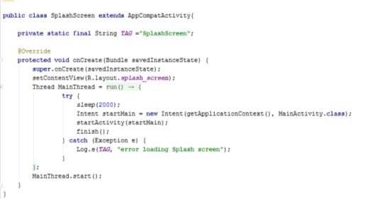
The first page consisted of a Welcome page also known as a splash screen containing a background image with the MIL and the application name. The splash screen shows for 2 seconds then moves to the next page this was achieved by creating a thread and making the application stop on this page for 2 seconds(ADD YOUTUBE). The intent method was used to allow the application move to the next class and progress to the next activity (See Fig 21)
 The second page is the menu page in where it shows the user a list of available paired devices. To create the drop down in android studio menu xml file is required and then it needs to be programmed to show once the user selects an option (See fig 22). The inflate method is called upon to drop down the menu and like making the splash screen go to the main page the intent function is used to make the button search for paired and new devices to connect to.
Figure 20:Splash Screen
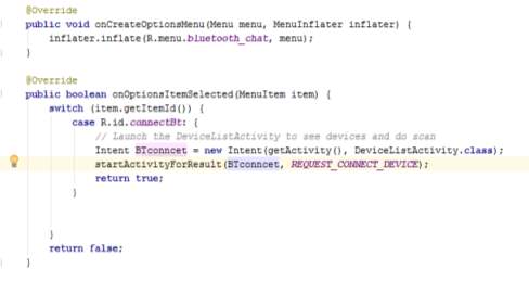
Figure 21:Menu Code
The third page originally had 4 buttons and a list view for the conversation, this has been changed include a text input as well to allow users to enter any specific commands they wish to send to the ECU. The first button will allow the user to check for error codes this was done by initialising a button called “GetCodes” and then defining it so when it is clicked on it would send the code “03” this will ask the ECU to obtain any faults that have been logged in the ECU (See fig 23). The second Button is the send button which will send the message that the user has typed in the “SentText” field (See Fig 23).
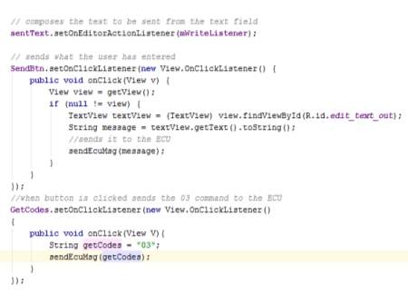
Figure 22:Button Code
The third button (clear code) is coded similar to that of the Get codes button however instead of sending “03” it will send “04” and this small change will tell the ECU to clear its log of error codes after this button has been pressed if the user presses get codes the previous codes should be cleared (see Fig 23).
The fourth Button will take the user to “fuel consumption” page where it will show the user live data of fuel consumption (See Appendices M). The Fuel Consumption page has no functionality implemented this was due to lack of time as well as limited knowledge of how to keep a continues read on a specific parameter ID. However, the page was still created therefore once the user clicks on the live Data button it will take them to a page containing a basic table in which the information would be displayed for the benefit of the report false data has been entered. The page was created like the splash screen with an intent method embedded within the function of the button.
Trouble code Implementation
To implement the functionality of reading and analysing the fault codes, this was difficult to achieve as the application needs to read from the ECU and then cross reference it with a class containing all known codes(see Fig25). To accomplish this functionality, the trouble codes are kept in a separate class for easy understanding. Once the ECU gives a trouble code it is stored in an array as it is possible for the vehicle to have more than one trouble code. Once the Trouble code array has something within it the it is cross checked with the Fault code class and checks if the code is known. Along with the error code there are descriptions of what the code means. As the error code is crossed checked if there is a description with the code it will be displayed however if the error codes are not within the class it will show just the error code. In the case of no error code the user will be informed of this situation. During implementation for this stage, some key errors had appeared such as the one shown below, (See fig 24) this occurred due to the fact the variables where set but not initiated. Therefore, to overcome this all that was required was to initiate the variable.

Figure 23:Trouble Code Error
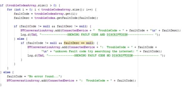
Figure 24:Trouble Code
Application Testing and Result Analysis
Once the application was created, several different types of testing was conducted such as Usability Testing, Low Level testing, compatibility testing and general testing
Usability Testing
This type of test is implemented to assess the interface of the application and that it is capable of successfully meeting “user’s expectation with respect to meeting” (Seela, 2017) productivity and usefulness in a simple method.
The usability tests the user interface of the system also looking at how user friendly the application can be. Several tasks were conducted to determine whether the application successfully pass the ease of use test. When approaching the test several factors from the usability section were taken into consideration to see if the Heuristics that have been mentioned above have been met to a sufficient standard. The table below shows the functionalities that have been tested.
| Test Number | Test Description | Expected Outcome | Actual outcome |
| 1 | The Application should load within a reasonable time. | The application should display the splash screen only for 2 seconds | The application loaded within the expected 2 seconds |
| 2 | The application should inform the user if the Bluetooth is not enabled once the application is loaded | A dialog box should request the user to activate their device’s Bluetooth | The application asks the user to enable Bluetooth if they already haven’t |
| 3 | The application should request a connection | If there is no connection made it application should ask the user to connect to a device | The application does not do this the person must manually select the option from the drop-down menu |
| 4 | The application should close if the user has not enabled their Bluetooth | The application will close if the user selects no to enable their Bluetooth | The application successfully closes if the user does not enable their Bluetooth |
| 5 | Once the device has connected the user should be informed of the device they have been connected to | A message will appear to let the user know the device they have connected to | The application tells the user the device name once it connects to the device |
| 6 | The main functions of the application are easily available with a reduced amount of manoeuvrability. | The application should display the main function on the first page | The main functionalities of the application are on the main page and are easily accessible |
| 7 | The application should contain a consistent theme | The main theme should be displayed across all pages | A consistent theme with a tyre tread background image and light blue text are carried through-out the application |
| 8 | The application should display information understandable to the user | The application should be in English and not display any code | The application is in English however when certain request is sent to ECU it will display non-understandable numbers |
The results of this test show majority of the functions incorporate usability features however due to the result of test number 3 and 8 the application isn’t as user friendly as possible, this shows some aspects of the application could be improved, however 6 out of the eight tests carried out showed positive results giving an overall satisfactory usability rating.
Low level resource testing
Low level resource testing was also conducted. This type of testing is used to help acknowledge the lower level uses of the application such as the amount of memory used while using the applications main functionalities, the amount of processing speeds achieved. Within android Studio there is a feature called Android monitor which has helped record data from the application such as the Memory consumed as well as how much is originally taken up by the application along with percentage of CPU used by the application. The reason for the Low-level test is due to the fact the applications should not consume too much resources of the mobile device as it could lead the app becoming non-user friendly as it would result in the application crashing. While recording the consumption of the resources the main functionalities of the applications were performed to give an idea of how the application would uses these resources within standard usage. Is when the application is loaded as you can see the CPU usage does not exceed 4% while loading, however the memory near full when started.
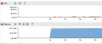
| Test Number | Test Description | Expected Outcome | Actual outcome |
| 1 | when turning on Bluetooth | Around 3 % of CPU usage along with leaving having a 5MB free allocated memory | Uses 1.76% CPU and had 3.25 MB free |
| 2 | When connecting the Bluetooth to a device | Around 4 % of CPU usage along with leaving having a 3MB free allocated memory | Uses 2.12% CPU and had 2.35 MB free |
| 3 | When sending, and receiving data | Around 5 % of CPU usage along with leaving having a 2MB free allocated memory | Uses 1.76% CPU and had 1.48 MB free |
Compatibility Testing
This testing was conducted on two fronts, first being to see if the application is compatible on multiple devices the second was to see if the application would work with different vehicles. A compatibility test is vital when creating an application. The compatibility test is used to check the application works as intended for multiple platforms and devices this helps broad user audience therefore making it vital to implement compatibility test.
| Test Number | Test Description | Expected Outcome | LG | Samsung | HTC |
| 1 | Does the application main functions work as intended | The applications main functions should work as normal | Yes, the main functions work normally | Yes, the main functions work normally | Yes, the main functions work normally |
| 2 | Is usability compromised depending on device | The usability should not be compromised | No | No | No |
| 3 | Does the layout differentiate depending on different device | The layout should be consistent through-out all devices | No, the layout was the same but the image quality was compromised | No | No, the layout did not change |
The results of this test show the application is capable of working on multiple platforms and accessible on different screen sizes, as per the Android studio developer website states “it’s important that you design your application to be compatible with all screen sizes”, By implementing a relative layout this compensates for many screen sizes as shown in the table above. The key factor for this test was to make sure the main functions work as intended and that the usability of the application is not compromised. The application passes all the tests conducted, making this test successful for the application.
To check if the application works with multiple vehicles a test was conducted with three different makes, using different ECU protocols. The results were as assumed the application worked as intended reading faults and communicating with the ECU to a satisfactory standard. The reason the application could work fine with different types of vehicles was down to the ELM device it was tested with. This is because the device chosen could communicate with all 5 protocols mentioned in the Research section
| Test Number | Test Description | Expected Outcome | Toyota | Renault | Vauxhall |
| 1 | Are car faults read | The application should still read codes if the elm device can communicate with the ECU | Yes, the main functions work normally | Yes, the main functions work normally | Yes, the main functions work normally |
| 2 | Does the ELM device communicate with the ECU | The elm device should communicate with the vehicle protocols | Yes | Yes | Yes |
General Testing
A general test was conducted to make sure the main objectives were met by the application.(See table 1)As per results of the tests conducted against the main objectives the result is positive and showed the majority of the outcomes were successful in achieving the intended objective, although objective five was unable to view the information in a user-friendly way, the main function of the object was to allow the user to send personal parameter ID’s, this is done but the returned data is not useful, therefore ultimately resulting in a fail for this objective.
All testing was conducted on mobile devices instead of the built-in emulator since the emulator does not support Bluetooth testing (Emulator, 2017).
Discussion and Evaluation
This section will entail how the project progressed, including a critical evaluation of the project. Stating positive aspects, difficulties encountered, by what method they were overcome.
Before conducting the design and implementation phases, a preliminary set of functions and features were considered and noted down after research material had been evaluated. These features and function partially influenced how the design and build of the application was constructed. In addition to this the application constructed is a prototype and not ready for the Android market, this was another factor in which affected the development of the application. Within the development of the prototype some sophisticated functions needed to be implemented as well as some basic features. Due to the fact of having access to multiple android based devices along with the vast amount of knowledge available to android Developers, this had swayed the construction of the application to become that of an android base application. Developing the application within Android Studio has helped increase the knowledge obtained within the project furthering skills not only within java programming language but also increasing the understanding of android based XML documentation and increased knowledge of how Bluetooth functions.
To help construct the application and increase the amount of knowledge to possibly obtain, the implementation of the Bluetooth function was constructed using the information available on the developer website as stated in the research section, along with tutorials and books on how to program with java. Having previous experience with java made it less difficult to understand or implement solutions to some of the problems that may have situated. However, if a novice were to start it could turn out to be a bit difficult. One major area throughout this project that has improved is the understanding of Bluetooth network connectivity such as the importance of both the client side and server side connections as well as their key roles and functions. Not only the understanding of Bluetooth has increased but also the different types of alternatives there are for example NFC and Wi-Fi and what they can achieve.
As mentioned before some preliminary functions and features were noted. One of these ideas were to implement Bluetooth connectivity, although there may be better alternatives to Bluetooth as mentioned in the research. Bluetooth is more than capable of achieving what is required for this project. One of the key factors is to be able to connect within a suitable proximity of the user device and the OBD reader. It should also send and receive data within real time speeds. When implementing the Bluetooth network communication several errors occurred, especially when trying a read the data from the OBD reader to overcome the problem a tutorial explaining how data is transferred between two Bluetooth modules was watched and followed. To expand the knowledge of the java language books were read and tutorials were followed. The books helped understand how to use if statements (Wu, C. 2010). and how to implement for loops to increment the string being read from the ECU. Following a few tutorials, I could implement a splash screen, main data transferal page, device list page, and dialog page for the paired devices.
When implementing the Design to the application the ten heuristic were considered as well as androids own guide on how to make applications. This helped design a simple application with good usability features.
During the final testing of the application, a few problems were encountered. The main problem being the application would crash when trying to a connection was being established, along with freezing on the main page, after thorough investigation these, problems were sought out and corrected for the crash it was due to the “leaked window” error as mentioned above, and the reason the application would freeze was down to the app being stuck within a while loop statement.
Another major issue with the application is the real-time data display. The application can obtain the data however it does not convert that data into understandable figures for the user to process. A simple solution to rectify this problem would to implement another view for the data to show up in a possible using a formula to convert the data into a steam of readable figures and be displayed in a fuel gauge with some simple output figures of the fuel consumption. This solution was attempted however due to time constraints and lack of knowledge the solutions could not be implemented.
Limitations and Future Improvements
The primary limitations were due to limited knowledge on Android application development. Android application development is a complex and time consuming endeavour, with ever changing aspects of the Android environment and functionalities. Future improvement can be implemented by gaining a greater knowledge base, gathered over time by developing further applications with different and multiple features. With future improvement, a widget feature could also be implemented to show the “My Simple OBD Application” data on the home page of the user’s device.
“My Simple OBD Application” limitations
The OBD application isn’t the final version. Due to time constraints, it was not possible to include all the desired functionality to make it commercially marketable. However, the application does contain the main features set out in the preliminary objectives (See Table 1). With greater development and knowledge these objectives would have been met. A future improvement for the application could be to incorporate the Google web API (Amongst others) this could be used when a DTC code is found the user could click on the code and the “My Simple OBD Application” would display a web browser window within the application allowing users to do detailed research of the obtained DTC.
Real-time data Analysis Limitations
The limitation to real time data analysis is the CAN bus protocol that is used for vehicle communication is shared therefore different data sources will compete for bandwidth (See Table 4). The more sensors being monitored for real-time data viewing by the OBD Application will cause the sample rate of all sensors to diminish due to contention on the bus (ADD REFERECE 1). However, speeds of the Bluetooth Network as mentioned in the research section(Section 3.5.1.4) , this in theory should be more than capable to handle the amount of data received from the OBD device. Vehicle computational processing power is constantly increasing therefore it is logical to believe that newer CAN protocols will be implemented, that should allow higher data transfer speeds.
Alternative method to further improve the “My Simple OBD Application” would be to incorporate Wi-Fi capabilities as stated in the literature review Wi-Fi is capable of faster data transfer speed while covering a greater distance, such as the Torque application which is on the play store.
Usability Limitations
One of the usability limitations present is the fact that the android Accessibility API is not incorporated in the “My Simple OBD Application”. This API would allow vision impaired users to listen to data from the application. This can be overcome by simply incorporating the API, this solution should rectify the limitation and improve the overall usability of the application. Another key usability limitation is the “My Simple OBD Application” does not inform the user if the application is connected to a device or not when the application is started it only checks if the Bluetooth is enabled. To overcome this, a simple solution is to show a toast that states whether the “My Simple OBD Application” is connected to a device or not.
Conclusion
The purpose of this project is to develop a free android based application using the Bluetooth network protocol connectivity that allows inspection of a vehicles DTC faults codes that are stored within the ECU by connecting an android application to the Bluetooth enabled OBD reader. Delivering a user-friendly GUI can help users to easily understand and monitor the information about their vehicles parameters. The “My Simple OBD Application” is demonstrated in real time to show the effectiveness of the system. This also provides evidence the application delivers a user-friendly GUI.
Employing the Bluetooth Network connectivity in Android applications can be unnerving for those unaccustomed with the procedure. However, with no prior experience with Android’s Bluetooth API or programming within Android studio, leading to the project being difficult, and frustrating at times. Although this has led to a tremendous learning curve, improving many factors such as furthering the knowledge of Bluetooth connectivity as well as advancing java programming skills.
From the discussion, along with the objectives, the real-time data display functionality was intended to be incorporated in to the “My Simple OBD Application” however due to the limitations mentioned in the study (Section8) it was not able to be incorporated. This and the other further improvements should be addressed at a future stage.
To help with further development of the “My Simple OBD Application” it is possible to place it on the Google play store as a demo allowing customers to be able to leave feedback. Many android developers use this tactic to implement any further improvements users request, thereby improving the application to suit the intended target.
Connectivity and automation has rapidly transformed the automotive industry and offers a range of opportunities and possibilities. All personal and organizations interested within this field should stay up to date with the knowledge and information since this is a rapid developing and altering sector.
Some of the factors where further research and development is required, is within the CAN bus protocol and hardware that is used for the vehicle communication. As mentioned within the limitations section (Section 3.6.1). Along with this further research is required in the literature available. Such as other fields the OBD could be used for e.g. implementation of Speed awareness.
The overall success of the project is determined by whether the main objectives stated have been met to a substantial standard or not. Looking back at the general tests conducted where the “My Simple OBD Applications” main objectives where thoroughly put through their paces, the results show five out of the six main objectives have been successful. Overall the project can be considered as a success even though the fifth objective had failed.
References
Wu, C. (2010). An introduction to object-oriented programming with Java. Boston: McGraw Hill Higher Education.
Y. Yang, B. Chen, L. Su, and D. Qin, “Research and development of hybrid electric vehicles can-bus data monitor and diagnostic system through obd-ii and android-based smartphones,” Advances in Mechanical Engineering, vol. 5, pp. 74–89, 2015.
Kumar, T. and Sivaji, S. (2015). Android Based vehicle monitoring and tracking system using ARM7 and CAN techhnology. International Journal of Science Engineering and Advance Technology, 03(04), pp.94-98.
Malekian, R., Moloisane, N., Nair, L., Maharaj, B. and Chude-Okonkwo, U. (2017). Design and Implementation of a Wireless OBD II Fleet Management System. IEEE Sensors Journal, 13(9), pp.1-10.
Zaldivar, J., Calafate, C., Cano, J. and Manzoni, P. (2011). providing accident detection in vehicular Network through OBD-ii devices and android based smartphones. Conference on Local Computer Networks, pp.813-819.
V. Malpani, S., D.Deshmukh, A., S.sakore, G. and K.Bhatia, S. (2015). Android Dashboard and smart vehicle managment. International Journal of Advanced Research in Computer Engineering & Technology, 4(3), pp.1020-1022.
Tahat, A., Said, A., Jaouni, F. and Qadamani, W. (2012). Android-based Universal Vehicle Diagnostic and Tracking System. pp.137-143.
Kene, S. and Khisti, C. (2014). VEHICLE DIAGNOSTICS USING BLUETOOTH AND GSM MODULE. pp.36-39.
Nille, G., Yadav, D., Jadhav, V. and Nagargoje, P. (2015). Wireless Vehicle Monitoring and Safety System. European Journal of Advances in Engineering and Technology, 2(4), pp.90-94.
Ganapati, P., Popatrao, G., Dattatraya, B. and Kadu, R. (2014). Android Based Universal Vehicle Diagnostics and Tracking System. International Journal of Modern Engineering & Management Research, 2(1), pp.3
Bibliography
Appendices
References
Wu, C. (2010). An introduction to object-oriented programming with Java. Boston: McGraw Hill Higher Education.
Y. Yang, B. Chen, L. Su, and D. Qin, “Research and development of hybrid electric vehicles can-bus data monitor and diagnostic system through obd-ii and android-based smartphones,” Advances in Mechanical Engineering, vol. 5, pp. 74–89, 2015.
Kumar, T. and Sivaji, S. (2015). Android Based vehicle monitoring and tracking system using ARM7 and CAN techhnology. International Journal of Science Engineering and Advance Technology, 03(04), pp.94-98.
Malekian, R., Moloisane, N., Nair, L., Maharaj, B. and Chude-Okonkwo, U. (2017). Design and Implementation of a Wireless OBD II Fleet Management System. IEEE Sensors Journal, 13(9), pp.1-10.
Zaldivar, J., Calafate, C., Cano, J. and Manzoni, P. (2011). providing accident detection in vehicular Network through OBD-ii devices and android based smartphones. Conference on Local Computer Networks, pp.813-819.
V. Malpani, S., D.Deshmukh, A., S.sakore, G. and K.Bhatia, S. (2015). Android Dashboard and smart vehicle managment. International Journal of Advanced Research in Computer Engineering & Technology, 4(3), pp.1020-1022.
Tahat, A., Said, A., Jaouni, F. and Qadamani, W. (2012). Android-based Universal Vehicle Diagnostic and Tracking System. pp.137-143.
Kene, S. and Khisti, C. (2014). VEHICLE DIAGNOSTICS USING BLUETOOTH AND GSM MODULE. pp.36-39.
Nille, G., Yadav, D., Jadhav, V. and Nagargoje, P. (2015). Wireless Vehicle Monitoring and Safety System. European Journal of Advances in Engineering and Technology, 2(4), pp.90-94.
Ganapati, P., Popatrao, G., Dattatraya, B. and Kadu, R. (2014). Android Based Universal Vehicle Diagnostics and Tracking System. International Journal of Modern Engineering & Management Research, 2(1), pp.35-41.
Cite This Work
To export a reference to this article please select a referencing stye below:
Related Services
View all


Related Content
All TagsContent relating to: "Automotive"
The Automotive industry concerns itself with the design, production, and selling of motor vehicles, such as cars, vans, and motorcycles, and is home to many multi-billion pound companies.
Related Articles

DMCA / Removal Request
If you are the original writer of this dissertation and no longer wish to have your work published on the UKDiss.com website then please: