Android App for Household Services
Info: 11018 words (44 pages) Dissertation
Published: 7th Jul 2021
Tagged: Information SystemsTechnology
A PROJECT REPORT ON HOUSEHOLD SERVICES @ FINGER TIP
ABSTRACT
Now a days for any services like Plumbing, Electrical, Electronic, Mechanical, Pest Control, Home Paint and Machine Repairing, if any customer wants to use this type of services than they can go through a personal meeting or mobile call. It is difficult for customer to find any service in emergency at any time and place. So with this project we are going to develop website and android app which will help customers to find out solution for any problems related to Plumbing, Electrical, Electronic, and Mechanical, Pest Control, Home Paint and Machine Repairing service. Our website and android application will provide a platform for all kind of house hold services at any time and place. Our project will also provide the facilities like security, online payment, map navigation and also advertisement.
Table of Contents
| Chapter No. | Contents | Page No. |
| Acknowledgement | III | |
| Abstract | IV | |
| List of Figures | VII | |
| List of Tables | VIII | |
| 1 | Introduction……………………………………………….. | 1 |
| 1.1 Project Summary………………………………………………….. | 1 | |
| 1.2 Purpose……………………………………………………………. | 2 | |
| 1.3 Scope……………………………………………………………… | 2 | |
| 1.4 Report Outline…………………………………………………….. | 2 | |
| 2 | Literature Review………………………………………… | 4 |
| 3 | Project Management……………………………………… | 5 |
| 3.1 Project Planning and scheduling………………………………….. | 5 | |
| 3.1.1 Project Development Approach………………………………. | 5 | |
| 3.1.2 Project Plan…………………………………………………… | 7 | |
| 4 | System Requirements Specification……………………… | 8 |
| 4.1 User Characteristics……………………………………………… | 8 | |
| 4.2 Hardware and Software Requirements…………………………… | 9 | |
| 5 | System Analysis…………………………………………… | 10 |
| 5.1 Feasibility Study………………………………………………….. | 10 | |
| 5.1.1 Technical Feasibility………………………………………….. | 10 | |
| 5.1.2 Economical Feasibility……………………………………….. | 10 | |
| 5.1.3 Operational Feasibility……………………………………….. | 10 | |
| 5.2 Functions Of System……………………………………………… | 11 | |
| 5.2.1 Use Case Diagram…………………………………………… | 11 | |
| 5.3 Data Modeling……………………………………………………. | 13 | |
| 5.3.1 E-R Diagram………………………………………………….. | 13 | |
| 5.3.2 Activity Diagram……………………………………………… | 14 | |
| 5.3.3 Sequence Diagram……………………………………………. | 16 | |
| 5.4 Functional and Behavioral Modeling…………………………….. | 20 | |
| 5.4.1 Data Flow Diagram……………………………………………
5.5 Database Schema Design…………………………………………. 5.6 Canvas……………………………………………………………. 5.6.1 AEIOU Canvas…………………………………………….. 5.6.2 Empathy Summary Canvas………………………………… 5.6.3 Ideation Canvas…………………………………………….. 5.6.4 Product Development Canvas……………………………… 5.6.5 Business Model Canvas……………………………………. |
20
24 26 26 27 28 29 30 |
|
| 6 | Implementation……………………………………………
6.1 Testing……………………………………………………………. 6.2 Test Case………………………………………………………….. 6.3 Important Screenshots……………………………………………. |
34
34 35 36 |
| 6.4 Sample Code………………………………………………………. | 37 | |
| 7 | Conclusion………………………………………………… | 55 |
| References…………………………………………………. | 56 | |
| Appendix…………………………………………………… | 57 | |
List of Figures
| Figure No. | Figure Name | Page No. |
| 3.1 | Iterative Waterfall Model……………………………………………… | 5 |
| 3.2 | Gantt Chart For Project Schedule………………………………………. | 7 |
| 5.1 | Use Case Diagram For Admin………………………………………… | 11 |
| 5.2 | Use Case Diagram For Service Provider………………………………. | 12 |
| 5.3 | Use Case Diagram For Customer……………………………………… | 12 |
| 5.4 | E-R Diagram Of The System………………………………………….. | 13 |
| 5.5 | Activity Diagram For Login& Registration…………………………… | 14 |
| 5.6 | Activity Diagram For Admin………………………………………….. | 15 |
| 5.7 | Activity Diagram For Service Provider……………………………….. | 15 |
| 5.8 | Activity Diagram For Customer……………………………………….. | 16 |
| 5.9 | Sequence Diagram For Admin………………………………………… | 17 |
| 5.10 | Sequence Diagram For Service Provider……………………………… | 18 |
| 5.11 | Sequence Diagram For Customer……………………………………… | 19 |
| 5.12 | DFD Diagram Level 0…………………………………………………. | 20 |
| 5.13 | DFD Diagram Level 1 For Admin…………………………………….. | 21 |
| 5.14 | DFD Diagram Level 1 For Service Provider………………………….. | 22 |
| 5.15 | DFD Diagram Level 1 For Customer………………………………….. | 23 |
List of Tables
| Table No. | Table Name | Page No. |
| 1 | Database table for admin login……………………………………….. | 24 |
| 2 | Database table for service_register…………………………………… | 24 |
| 3 | Database table for customer_register…………………………………. | 24 |
| 4 | Database table for order_service……………………………………… | 25 |
| 5 | Database table for category…………………………………………… | 25 |
| 6 | Database table for reply_detail……………………………………….. | 25 |
| 7 | Database table for feedback…………………………………………… | 25 |
Chapter 1: INTRODUCTION
In this fast growing technology, we still have to take the appointment of person who solve the problems related to our daily life like plumbing related problem, mechanical problem, electrical problem, electronic problem, pest control etc.
To take the appointment of service provider we have to call him or with the personal meeting we can meet him, and it is not sure that we get the appointment of the service provider at a time because there are many problems occur, like the service provider is busy at somewhere else or he is not present at his office when we go there or he wants heavy cost for fix the problem etc.
We are not getting any service on time and also not proper changes of services. It is also not secure in terms of safety concern.
To overcome these type of problem we are going to make our android application and website where the people get appropriate result.
This android application and website is very dynamic and very easy to understand. The interface of the android application and website is very easy and anybody can easily work on it. This android application and website can provide all the description and important information about the problem.
The Household service android application and website is also very useful because the customer don’t have to visit to service provider’s office, he/she can easily book his/her order via this application and he/she can also pay the payment online in this android application and website. So he/she can book order without any kind of disturbance. Our android application and website is secured with QR code. It will provide security for the customer.
To make this application work successfully we have used some latest technology such as Android as the platform and My sql as the database management environment.
The UML diagram has been drawn which is useful to display the flow of the process throughout the system so even an inexperienced people can easily get the idea of the proposed system.
1.1 Project Summary
The aim of project is to provide the services to the customers at reasonable rate. Through this project provide the facilities to the customer such as registration, display profile of service provider, advertisement, QR code, map navigation etc.
1.2 Purpose
Our purpose of developing this project is mainly online there website and android application.
We have observed how limitations in existing system:
- Existing system is offline.
- Difficult to manage records.
- No time limit for service to be provided.
- No guarantied service.
- Difficult to find paper service provider.
- 24 hours service is not available.
- No security.
So, our purpose is to overcome this limitation with following features.
- House hold services easy available.
- To provide house hold services any time.
- Easy online payment.
- Saving of time.
- Make available house hold services through website & application.
1.3 Scope
The scope of our project is to designing a complete environment to provide a safe and user friendly environment for online service booking. The main aim of the project is to provider an easy to use application for services provided for customer.
We often get frustrated while taking the appointment of service provider because there the many problems are occur, like the service provider is busy art somewhere else or his not receiving our call or his cost is very high according to problem. So in this project we will remove this headache.
1.4 Report Outline
Chapter 1 is the general introduction to the project. This gives the summary of project and itspurpose & the scope of this project.
Chapter 2 captures the literature review of the existing system its working & its advantages and disadvantages.
Chapter 3 captures the Planning and Scheduling details of the project which is first step towardsmaking project. This chapter includes models is being followed by us to develop a project, Project evaluation and review technique, the work plan of the project.
Chapter 4 introduces the use of the system and hardware and software required to implementthe system that is the system requirement & specification.
Chapter 5 covers the system analysis made by the developer of the system. This chapterincludes feasibility study made by the developer of the system. The chapter also covers the design analysis made by developer of the system which includes details of the use cases, ER Diagram, Dataflow diagram, sequence, and activity diagram which shows the functional and behavioral aspect of the system.
Chapter 6 describes the database schema design and data dictionary which shows the relations used in system as well as their relationship to each other.
Chapter 7 deals with the implementation details of the system. This chapter includes the static pages fordesigning the system.
Chapter 8 includes the conclusion & future work of the project.
Appendix describes the canvases of the system.
References it includes the references which we have referred for working on this project.
Chapter 2: LITERATURE REVIEW
We have observe so many problems which are occur in our daily routine, for example the problem of electricity, if the electricity goes there are many problems occurs in our work, like we cannot charge the phones, batteries etc. the electric devices which are used in kitchen cannot be work.
In existing system the whole process is offline and customer can not get proper solution for the problem. The existing system is not available for 24 hours, so the customer can not get solution for any time.
We also observe the problem of plumbing at our home, there is one type of plumbing problem is occur, In that situation what we will do. Firstly we call the plumber and take his appointment if available or we directly meet him for the appointment to fix the problem. This process is very time consuming and it is not sure that we get the appropriate solution for our problem.
We also noticed that if we are going somewhere and our vehicle is get suddenly stop. In this situation what we will do is that we call the mechanic to fix the problem which occur in our vehicle, and at one moment if we block in some place where no network is available in our phone and at that place the rush of traffic is very less so which kind of problem we have to faced. Firstly We have to find the mechanic and ask him for fix the problem. This process is very time consuming and it is not sure that we get the solution for the problem because many problems are occurs in that situation like mechanic is busy in other work or his payment is very high according to the problem etc.
By observing these type of problems we thought that, how can we get the solution of these type of problem in easy and appropriate way, then we get the idea to developing our android application and website where people can get any type of services like plumbing, electrical, electronics, pain, pest control etc.
In this stage of technology our application is very simple and easy to understand.
Chapter 3: PROJECT MANAGEMENT
3.1 Project Planning and scheduling
3.1.1 Project Development Approach
Our project is developed using specific software development lifecycle. Software development approach is best suited for the project depends on the requirement and other factors. A process model is a development strategy that is used to achieve a goal that satisfies the requirements abiding by the constraints.
Iterative Water Fall Model
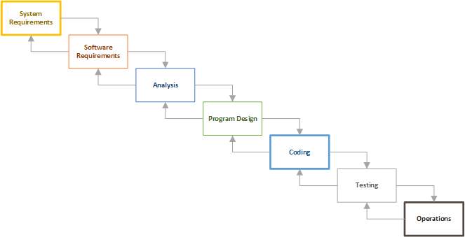
Figure 3.1 : Iterative Waterfall Model
Advantages of Iterative Waterfall Model
- This model is simple and easy to understand and use.
- It is easy to manage due to the rigidity of the model – each phase has specific deliverables and a review process.
- In this model phases are processed and completed one at a time. Phases do not overlap.
- Waterfall model works well for smaller projects where requirements are very well understood.
Analysis:The aim of the requirement analysis is to understand the exact requirements of the customer and to document them properly.
Requirement gathering and analysis: This activity consists of first gathering the requirement and then analyzing the gathered requirement.
Requirement Specification: The customer requirement identified during the requirement gathering and analysis activity are organized into a software requirements specification (SRS).
Design: The goal of the design phase is to transform the requirements specified in the SRS document into a structure that is suitable for implementation in some programming language. In technical, during the design phase the software architecture is derived from the SRS document.
Traditional Design Approach: The traditional design technique is based on the data flow-oriented design approach. While using this technique the design phase consists of two important activities: first a structured analysis of the requirement specification is carried out where the detailed structure of the problem is examined.
Object-oriented design approach: Object-oriented design approach (OOD) is a relatively new technique. In this technique, various objects that occur in the problem domain and the solution domain are first identified and the different relationships that exist among these object are identified.
Code:The purpose of the coding of software development is to translate the software design into source code. The coding phase is also sometimes called the implementation phase since the design is implemented into a workable solution in this phase. Each component of the design is implemented as a program module. The end-product of this phase is a set of program modules that have been individually tested. To enable the engineers to write good quality program, every software development organization normally formulates its own coding standards that suits itself. A coding standard addresses issues such as the standard ways of laying out the program code, the template for laying out the function and module headers, commenting guidelines, variables and function naming conventions, the maximum number of source lines permitted in each module, etc.
Testing:System testing is normally carried out in a planned manner according to a system test plan document.
Maintenance:Maintenance of a typical software product requires much more effort than the effort necessary to develop the product itself. Maintenance effort is roughly in 40:60 ratio.
3.1.2 Project Plan
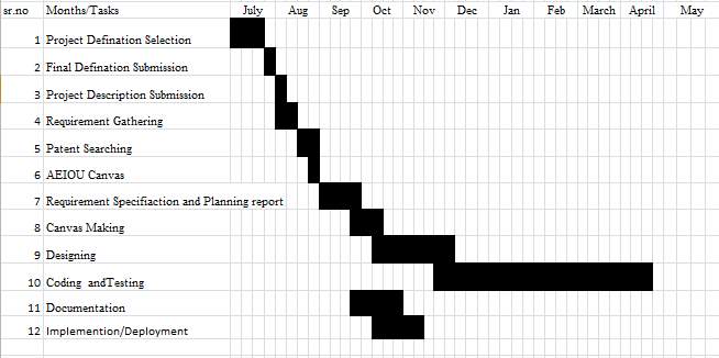
Figure 3.2 : Gantt Chart
Chapter 4: System Requirement Specification
4.1 User Characteristics
The users of the system include:
1. Admin
2. Service Provider
3. Customer
4. Shopkeeper
- Admin
Administrator has maximum privileges to access the system. He maintains user login details, can assign access rights to a user, can manipulate data and do all the transactions. Administrator is the super-user of the system.
He/She can verify service provider and customer.
He/She manages all the categories of service.
He/She can take the payment from the customer.
He/She can add the new advertisement.
He/She can send notification to the customer and service provider.
He/She can give order for service instrument to the shopkeeper.
He/She can also comment to user.
- Service Provider:
In this android application service provider first do registration and then login after this process the service provider can view the service which are ordered by user and send acknowledgement to the user in positive reply. After that service provider get the QR code which is matched with the QR code of customer.in this application we are providing the map for the service provider to find his location. The then service provider comes at the place of customer then he verify the QR code with the customer and then do his work.
- Customer:
In this application the customer first do registration and then do login, after the user search for the particular service and receiver the list of service available on our android application. The user then selects the service and request for the service after this process
He/she can get acknowledgement as reply and get QR code which is unique for every user.
4.2 Hardware and Software Requirements
Hardware:
- Processor: Intel Pentium IV and above
- RAM: 1GB or more
- Hard disk 250 GB and more
Software:
- Operating System:
- Microsoft Windows XP and above
- Smart Phone :
Marshmallow
2 GB RAM
8 GB and more
- Front End:
- Eclipse Version : Indigo Service Release 2
- Back End:
- SQL Server 2008 R2
- Wamp Version 1.8.3-5
Others:
- Web Browser : Internet Explorer, Google Chrome, Mozilla Firefox.
Documentation:
- Microsoft Word 2010 and above
- Microsoft Excel 2010 and above
- Microsoft Visio 2010 and above
- Edraw Max 8.0
Chapter 5: SYSTEM ANALYSIS
5.1 Feasibility Study
Feasibility study is carried out when there is a complex problem or opportunity. It is considered as the primary investigation which emphasizes on “Look before You Loop” approach to any project .A Feasibility study is undertaken to determine the possibility of either improving the existing system or developing a completely new system.
We are going to developed the new system which is feasible as our application is very user friendly and easy to understand.
5.1.1 Technical Feasibility
In this type of study the current technology in used in an organization is checked such as the existing software, hardware, and personnel staff to determine whether it will work for the proposed system or completely new ones is to be used. The technology that was important in developing a new system such as Development tools, back-end database system were available from within the organization. The proposed system is capable of adding, changing, enhancing functionality, features etc. The proposed system is capable of handling large storage of data. The back-end and front-end technology has greater important for providing an accurate, error-free, frequencies of data to be used.
Our project is technically feasible in terms of current technology. Our project will provide latest platform like android technology.
5.1.2 Economical Feasibility
For proving that system developed is economical, the economical feasibility study takes place to check the cost of developing a system against the benefits that it provides. If the cost are less and benefits are more than we can define our system to be economically developed. User saves time in searching for a particular product to be purchased by simply few clicks. The registration process is speedier than the registered manually. The saving of papers as all data are stored computerized. The record is of free of human errors as there is less chance of mistakes. The above benefits are in terms of saving time, minimize errors and provide efficiency in work done.
In terms of economical feasibility our application is very reasonable in cost. So application is economically feasible.
5.1.3 Operational Feasibility
The operational feasibility is concerned with the operability of the system after it has been installed. That is, some programmer may not like changes in their routine method of work or has fear that they will lose their peer group .The following areas will have the operational feasibility in the proposed project
- The organization has approved this system as their working system.
- The User of the system has accepted the proposed system as their new working system and realized the benefits of it.
- The system will work in a proper way after it has been installed and the installation process is easy to use.
5.2 Functions of System
The function of the system consist of the Usecase Diagram which represents how the customer, Service Provider & admin interact with the system.
5.2.1 Use case Diagram
Use case diagrams are a set of use cases, actors and their relationships. They represent the use case view of a system. A use case represents a particular functionality of a system. So use case diagram is used to describe the relationships among the functionalities and their internal/external controllers. These controllers are known as actors.
ADMIN
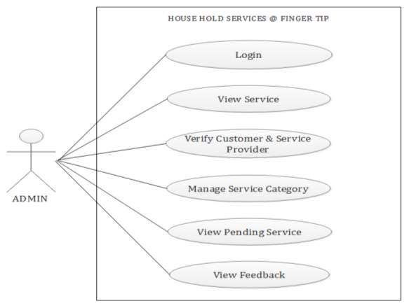
Figure 5.1 Use Case Diagram For Admin
SERVICE PROVIDER
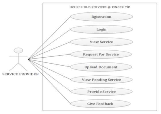
Figure 5.2 Use Case Diagram For Service Provider
CUSTOMER
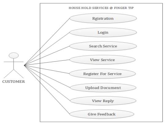
Figure 5.3 Use Case Diagram For Customer
5.3 Data Modeling
It consists of :
- E-R Diagram
- Activity Diagram
- Sequence Diagram
5.3.1 E-R Diagram
An entity-relationship diagram (ERD) is a graphical representation of an information system that shows the relationship between people, objects, places, concepts or events within that system. An ERD is a data modeling technique that can help define business processes and can be used as the foundation for a relation database.
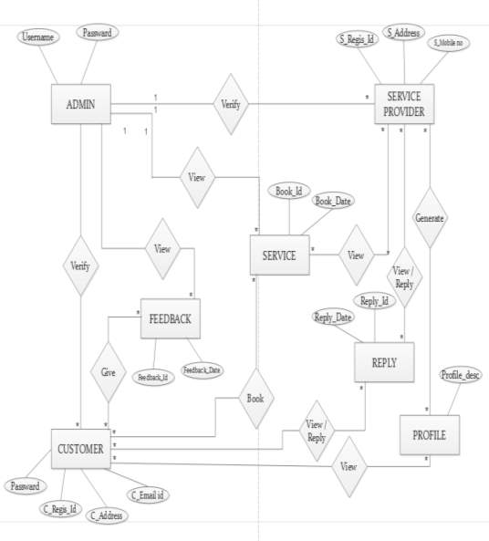
Figure 5.4 E-R Diagram
5.3.2 Activity Diagram
Activity diagram describes the flow of control in a system. So it consists of activities and links. The flow can be sequential, concurrent or branched.
Activities are nothing but the functions of a system. Number of activity diagrams are prepared to capture the entire flow in a system.
Activity diagrams are used to visualize the flow of controls in a system. This is prepared to have an idea of how the system will work when executed.
LOGIN & REGISTRATION
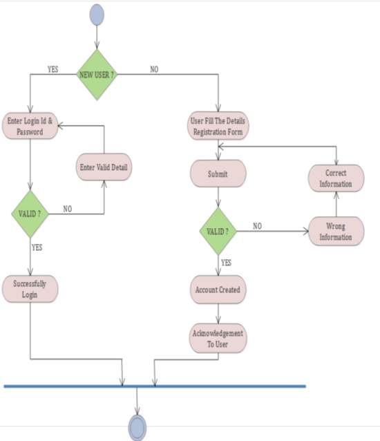
Figure 5.5 Activity Diagram For Login & Registration
ADMIN
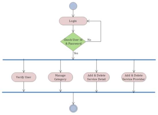
Figure 5.6 Activity Diagram For Admin
SERVICE PROVIDER
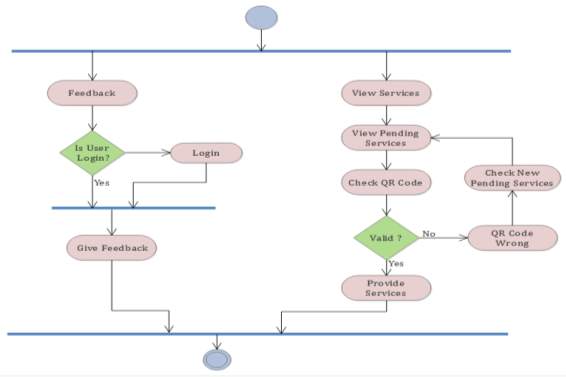
Figure 5.7 Activity Diagram For Service Provider
CUSTOMER
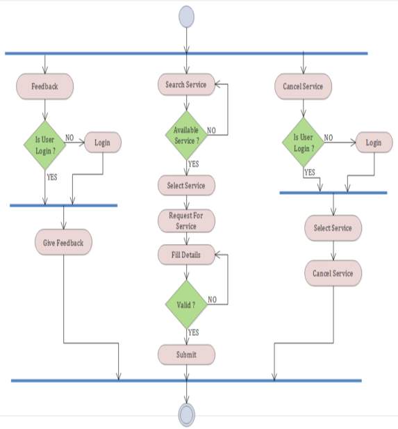
Figure 5.8 Activity Diagram For Customer
5.3.3 Sequence Diagram
A sequence diagram is an interaction diagram that shows how processes operate with one another and in what order. It is a construct of a Message Sequence Chart. A sequence diagram shows object interactions arranged in time sequence. It depicts the objects and classes involved in the scenario and the sequence of message exchanged between the objects needed to carry out the functionality of the scenario. They are typically associated with use case realization in the Logical View of the system under development.
ADMIN:
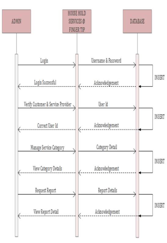
Figure 5.9 Sequence Diagram For Admin
SERVICE PROVIDER
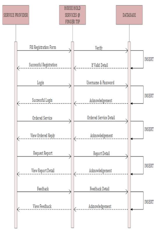
Figure 5.10 Sequence Diagram For Service Provider
CUSTOMER
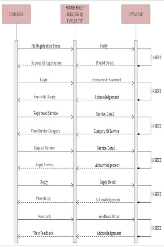
Figure 5.11 Sequence Diagram For Customer
5.4 Functional and Behavioral Modeling
It gives the basic description of the functions and the behavior of the system.
5.4.1 Data Flow Diagram
A data flow diagram is a graphical representation of the “flow” of data through an information system, modeling its process aspects.
A DFD shows what kind of information will be input to and output from the system, where the data will come from and go to, and where the data will be stored. It does not show information about the timing of process or information about whether processes will operate in sequence or in parallel.
DFD DIAGRAM LEVEL 0
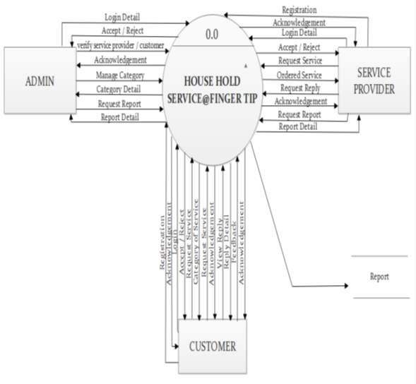
Figure 5.12 DFD Diagram Level 0
ADMIN
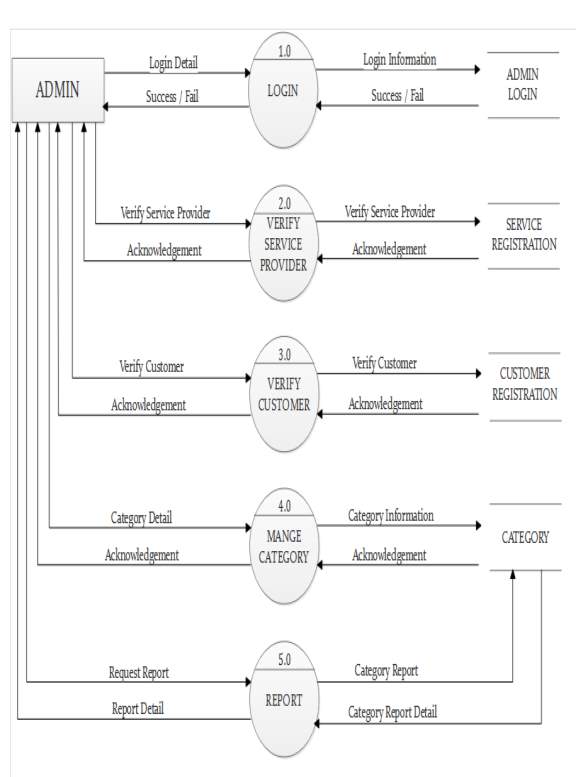
Figure 5.13 DFD Diagram Level 1 For Admin
SERVICE PROVIDER
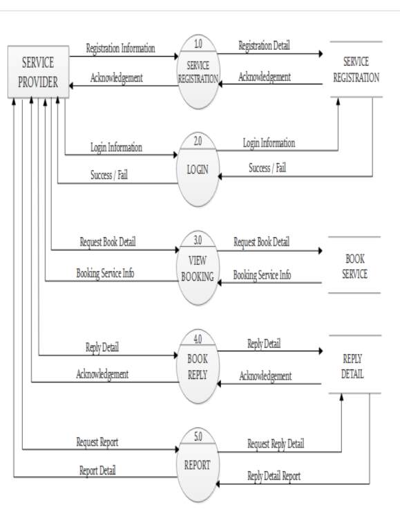
Figure 5.14 DFD Diagram Level 1 For Service Provider
CUSTOMER
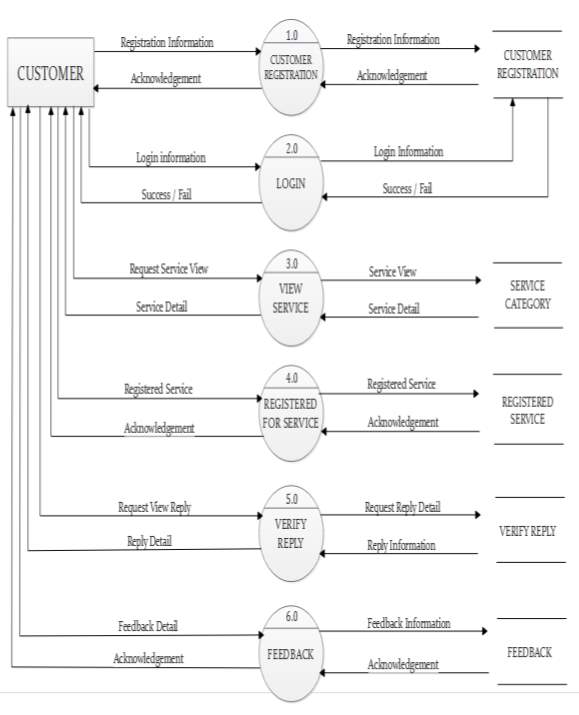
Figure 5.15 DFD Diagram Level 1 For Customer
5.5 Database Schema Design
ADMIN_LOGIN TABLE :
Table 1: Admin_Login Table
| COLUMN | DATATYPE | INDEXES | ALLOW NULLS |
| USERNAME | VARCHAR(50) | PRIMARY KEY | |
| PASSWORD | VARCHAR(10) |
SERVICE_REGISTRATION TABLE :
Table 2: Service_Registration Table
| COLUMN | DATATYPE | INDEXES | ALLOW NULLS |
| S_REGIS_ID | INT(10) | PRIMARY KEY | |
| S_NAME | VARCHAR(50) | ||
| ADDRESS | VARCHAR(255) | ||
| CITY | VARCHAR(50) | ||
| STATE | VARCHAR(50) | ||
| MOBILE NO | VARCHAR(10) | ||
| EMAIL ID | VARCHAR(50) | ||
| PASSWORD | VARCHAR(10) | ||
| CAT_ID | INT(10) | FOREIGN KEY | |
| S_LICENSE | VARCHAR(50) | ||
| PROFILE_DESCRIPTION | VARCHAR(255) | ||
| SERVICE_RATE | INT(10) | ||
| STATUS | INT(1) |
CUSTOMER_REGISTRATION TABLE :
Table 3: Customer_Registration Table
| COLUMN | DATA TYPE | INDEXES | ALLOW NULS |
| C_REGIS_ID | INT(10) | PRIMARY KEY | |
| C_NAME | VARCHAR(50) | ||
| ADDRESS | VARCHAR(255) | ||
| CITY | VARCHAR(50) | ||
| STATE | VARCHAR(50) | ||
| MOBILE_NO | VARCHAR(10) | ||
| EMAIL_ID | VARCHAR(50) | ||
| PASSWORD | VARCHAR(10) | ||
| AADHAR_IMAGE | VARCHAR(50) | ||
| STATUS | INT(1) |
ORDER_SERVICE TABLE :
Table 4: Order_Service Table
| COLUMN | DATA TYPE | INDEXES | ALLOW NULLS |
| ORDER_ID | INT(10) | PRIMARY KEY | |
| C_REGIS_ID | INT(10) | FOREIGN KEY | |
| S_REGIS_ID | INT(10) | FOREIGN KEY | |
| DESCRIPTION | INT(10) | ||
| ADDRESS | VARCHAR(255) | ||
| CITY | VARCHAR(50) | ||
| MOBILE_NO | VARCHAR(10) | ||
| BOOK_DATE | DATE | ||
| QR CODE | VARCHAR(20) | ||
| STATUS | INT(1) |
CATEGORY TABLE :
Table 5: Category Table
| COLUMN | DATA TYPE | INDEXES | ALLOW NULLS |
| CAT_ID | INT(10) | PRIMARY KEY | |
| CATEGORY | VARCHAR(50) | ||
| CAT_IMAGE | VARCHAR(50) |
REPLY_DETAIL TABLE :
Table 6: Reply_Detail Table
| COLUMN | DATATYPE | INDEXES | ALLOW NULLS |
| REPLY_ID | INT(10) | PRIMARY KEY | |
| REPLY_DATE | DATE | ||
| S_REGIS_ID | INT(10) | FOREIGN KEY | |
| C_REGIS_ID | INT(10) | FOREIGN KEY | |
| REPLY_MSG | VARCHAR(255) | ||
| SENDER_TYPE | VARCHAR(50) |
FEEDBACK TABLE :
Table 7: Feedback Table
| COLUMN | DATA TYPE | INDEXES | ALLOW NULLS |
| FEEDBACK_ID | INT(10) | PRIMARY KEY | |
| S_REGIS_ID | INT(10) | FOREIGN KEY | |
| DESCRIPTION | VARCHAR(255) | ||
| FEEDBACK_DATE | DATE |
5.6 CANVAS
5.6.1 AEIOU SUMMARY
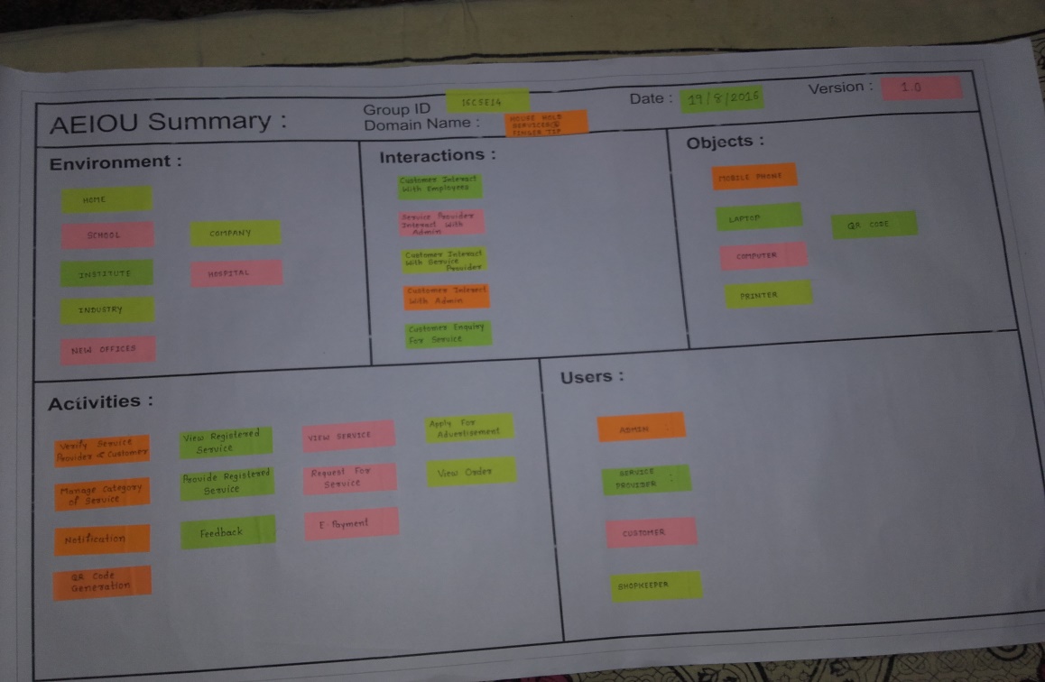
Description :
Environment
Environment describes the whether and atmospheric of a particular place at a given point of time.
Interaction
User will be interacting with the application to search the services, select the service, payment and booking the tickets.
The admin will be interacting with the application for validating the user by checking id proofs.
Objects
The objects that will be used while getting the whole process done are mobile, internet, ID proofs. The problem may occur while using these are invalid proofs, mobile number crashing.
Activities
The various activities that are performed while running the application are searching the services, selecting the services, booking the services and doing the payment. The admin will perform the activities like updating the services and other information.
Users
The users using the application can be customer, admin and service provider the problems can be there when the admin does not reply to the customers request and service provider is not ready for the providing the service.
5.6.2 EMPATHY SUMMARY
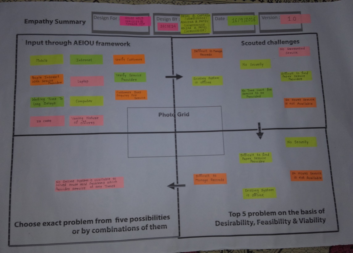
Description :
Input through AEIOU framework
The AEIOU framework gives us the summary of activities, environment, interaction, objects, and users involved in the system. The activities performed are uploading the services. The environment while using the system can be crowdy, noisy, warm. The interaction involved in the system can among customer and admin, service provider and admin, admin and shopkeeper, service provider and customer. The objects used in the system are mobile, laptop, computer and internet connection. The users involved are admin, service provider and shopkeeper.
Scouted Challenges
The challenges faced while using the system are time consuming, no commitment, there is no fix payment amount for service. Among these problems the exact problem is offline system is available to overcome these problems.
5.6.3 IDEATION CANVAS
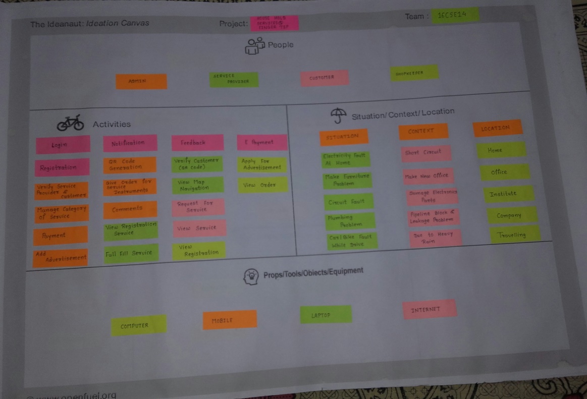
Description :
People
This system is useful and will solve the many problems of the people like customer and shopkeeper. The users involves in this system are admin, customer, service provider and shopkeeper.
Activities
The various activities related to our application are search service, booking service, select services, scanning QR code.
Situation/Context/Location
The situation can be different for different places for example at home the situation of power cut problem, at institute the situation of circuit fault will occur.
Props/Possible Solution
The different props that will be used while creating and using the system are mobile, laptop, computer, printer and internet connection.
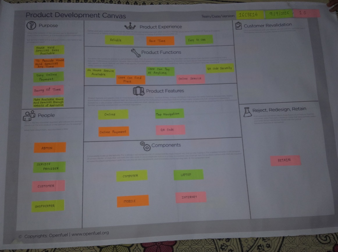
5.6.4 PRODUCT DEVELOPMENT CANVAS
Description :
Purpose
Our application targets at removing the problem of customer like taking the appointment of service provider with personal meeting with him or by calling, it is very time consuming and not giving appropriate result which is quite frustrating.
Product Experience
The application is created on android plateform so users can easily download it in their mobile and can book the services.
Components
The android application can be easily downloaded in the mobile and then can be used for searching the services and booking the services. The QR code scanner will be used for validating the user. Internet facility is necessary to run the application.
People
The list of people for whom both these application will be useful are customer, admin, service provider and shopkeeper.
Product Function
Product function deliver the product experience. The function we have included in our system to meet the customer experience are booking the service through android application, service cancellation facility.
Product Features
The features that we have included to enhance our system are QR code generating on in the application as security and the customer checking through QR code scanner for validating the user.
Customer Revalidation
To discover new user needs to know their reviews and solve their queries related to the application we have provided feedback and notification facility.
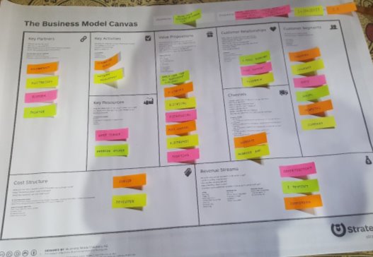
5.6.5 BUISSNESS MODEL CANVAS
Description :
Customer Segments:
Customer Segment block is to present the list of Persons, organized by Customer Segment. If you have more than one segment. It is always recommended to prioritize them.
Examples:
- Industry: problem occurs related to machinery at industry at that time our system is used.
- Collages: When the electronics parts may damage at collages our system can be used.
- Home: when furniture related problem occurs, our system may used.
- School: Our system is used when the problem of short circuit occurs at school.
- Hospital: when the problem occurs like electricity loss at hospitals our system can be used.
- Company: our system is used when some problem like pipeline block and leakage problem is occurred.
Value Propositions
The Value Propositions business block aims at providing answers to the following questions:
- What value do we deliver to the customer?
- Which one of our customer’s problems are we helping to solve?
- What bundles of products and services are we offering to each Customer Segment?
- Which customer needs are we satisfying?
Examples:
- Apply for the service: In this system user can apply for the services.
- View the services: User can view the services when he or she will apply for the services.
Channels
This business block comprises of a list of important Channels, linked to Personas or Segments if they differ substantially. Make notes on what steps are relevant for each- promotion, sales, service, etc. This business block provides answers to the following questions:
- Through which Channels do our Customer Segments want to be reached?
- How are we reaching them now?
- How are our Channels integrated?
- Which ones work best?
- Which ones are most cost-efficient?
- How are we integrating them with customer routines?
Examples:
- Website: user can also use the website of our system for applying for the services.
- Smart phone application: our system is android base so the user use this app with the help of smart phone.
- Internet: user will be able to use this app with the help of internet.
Customer Relationship
The customer relationship business block answers the following questions:
- What type of relationship does each of our Customer Segments expect us to establish and maintain with them?
- Which ones have we established?
- How are they integrated with the rest of our business model?
- How costly are they?
Examples:
- Email: user can also give the feedback through email or user can communicate with the system.
- Chat Support: user can communicate with the operator with the help of chat support.
- Feedback: user can give feedback related to services.
Revenue Streams
Revenue Streams block of Business Model Canvas aims at answering the following questions:
- For what value are our customers really willing to pay?
- What do they currently pay?
- How are they currently paying?
- How would they prefer to pay?
- How much does each Revenue Stream contribute to overall revenues?
Examples:
- Advertisement: we are advertising our application online.
- E-payment: user can do the payment using net banking or online payment or other payment applications.
Key Activities
The Key Activities block aims at answering the following set of questions in your business model:
- What Key Activities do our Value Propositions require?
- Our Distribution Channels?
- Customer Relationships?
- Revenue streams?
Examples:
- Literature Review: our system is online system, and it is very secure then offline system.
- Software Development: for developing the software we need software developer.
Key Resources
This segment of the business model canvas answers the following questions:
- What Key Resources do our Value Propositions require?
- Our Distribution Channels?
- Customer Relationships?
- Revenue Streams?
- Types of resources o Physical o Intellectual (brand patents, copyrights, data) o Human o Financial.
Examples:
- Wamp Server: We are using wamp server for developing the system.
- Android Studio: We are making an android app with the help of android studio.
Key Partnerships
It is always recommended to map Key Partners to Key Activities. If an activity is key, it’s still part of your business model. This is a way to denote which specific Partners are handling various Key Activities for you. This business block is intended to answer the following questions:
- Who are our Key Partners?
- Who are our key suppliers?
- Which Key Resources are we acquiring from partners?
- Which Key Activities do partners perform?
Examples:
- Government: our system is government base application.
- Electrician: our app is used by electrician.
- Plumber: plumber can also use our app.
- Painter: our app is used by painter also.
Cost Structure
Cost Structure business block provides a list of Cost Structure elements with notes on their relationship to Key Activities. This block in the business model answers the following questions:
- What are the most important costs inherent in our business model?
- Which Key Resources are most expensive?
- Which Key Activities are most expensive?
Examples:
- Servers: our system has cost structure on server.
- Developer: our system has cost structure at developer side
Chapter 6: Implementation
6.1 Testing
Software testing is a critical element of software quality Assurance and represents the ultimate review of specification, design and code generation. Testing is an internal part of any system or project. If a system is implemented without being tested it may lead to an erroneous working and dissatisfaction on part of the customer. It will also prove disastrous to the reputation of the organization or the person who developed the system and lead to loss in business.
Keeping all these things in view, we left no stone unturned in testing our systems. It was tested keeping in view the different possibilities on part of the user. As human beings are prone to commit errors under different working conditions, we had to keep our vigil on different possibilities that can occur on part of the user.
The system was tested for validation, functional implementation and its navigation.
- Validation Testing:
The user must login to the system with his/her unique login name and password. The user must enter all mandatory fields. If he/she fails to do so then a warning message is issued.
- Functional Testing:
The entire system was divided into sub modules. Adding/Updating of user Information in the database is done.
- Navigational Testing:
The system was tested so that all the pages are properly accessible with their respective links.
To uncover the errors in the system we have done testing as follows:
- Input Checking:
In this phase we tested the validation process only. When users enter the data in the given text box or in grids, proper input format is checked. If entry required numeric data user is bounded to enter only numeric. If text (alphanumeric)data, then user is bounded to enter text data only also check for null values. Like this all entries of all input areas are tested.
- Condition Testing:
Condition testing is a method that exercises the logical condition contained in program module. All relational statements were individually examined and tested. Extreme case values are given for testing.
- Loop Testing:
Loops are cornerstones for the vast majorities of all implementation in software. Each loop is examined separately. Its end point values were given and terminating condition each case tested.
- Output Testing:
First step of testing is checking how friendly it is. Then its accuracy is checked, that is whether it can be present all relevant information, it can report missing less, data etc.
- Acceptance Testing:
In this type we run the system live data by actual user.
6.2. Test Case
| Test
case id |
Test case name | Input | Expected
Output |
Actual
Output |
Observation |
| 1 | User login | Email id and Password | Homepage open | Homepage open | Pass |
| 2 | User login | Email id and Password | Homepage open | Error message “Incorrect Email id or password”. | Fail |
| 3. | User Status | 1.Active
2.Inactive |
Access to homepage | When verified through Database | Pass |
| 4. | User Status | 1.Active
2.Inactive |
Access to homepage | When not verified through Database | Fail |
| 5 | Apply for the services | Apply for the services | Successfully apply for the services | Apply for the services successful | Pass |
| 6 | Apply for the services | Apply for the services | unsuccessfully apply for the services | Apply for the services unsuccessful | Fail |
| 7 | Generate the customer details | Generate the customer details | Successfully generate the details | Generated details success | Pass |
| 8 | Generate the customer details | Generate the customer details | unsuccessfully generate the details | Generated details unsuccessful | Fail |
6.3 Important Screenshots
ANDROID APPLICATION
WEBSITE
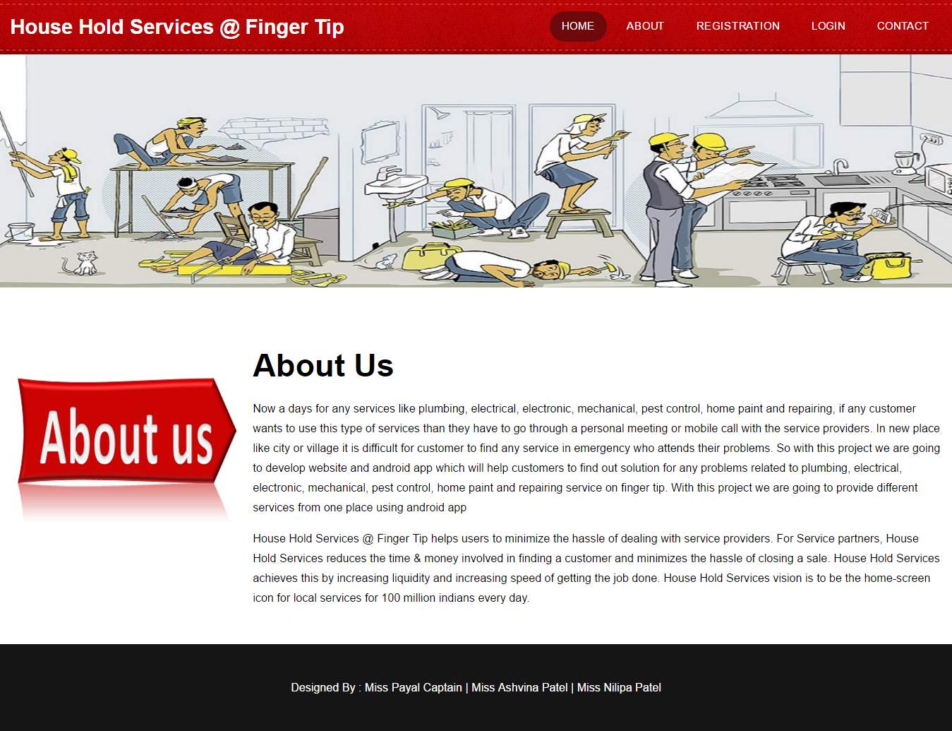
About Us page:
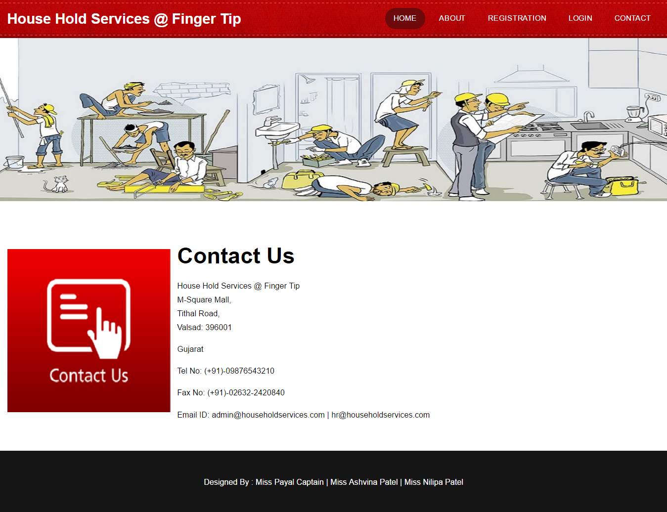
Contact Us page:
HomePage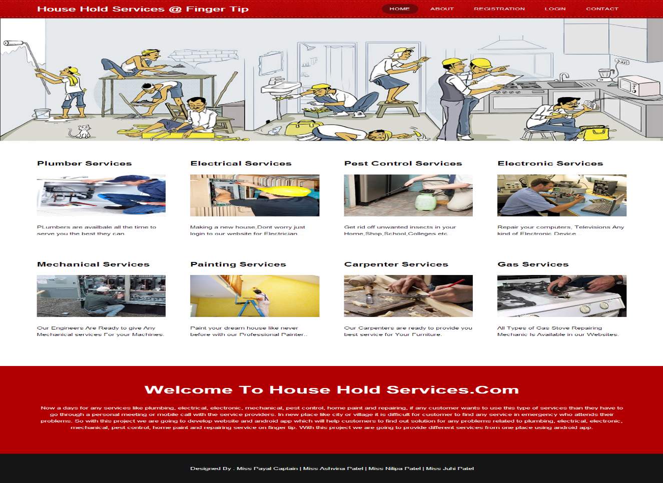
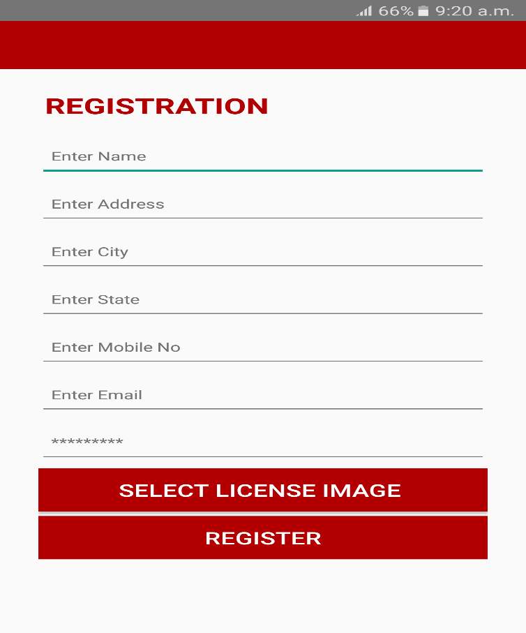
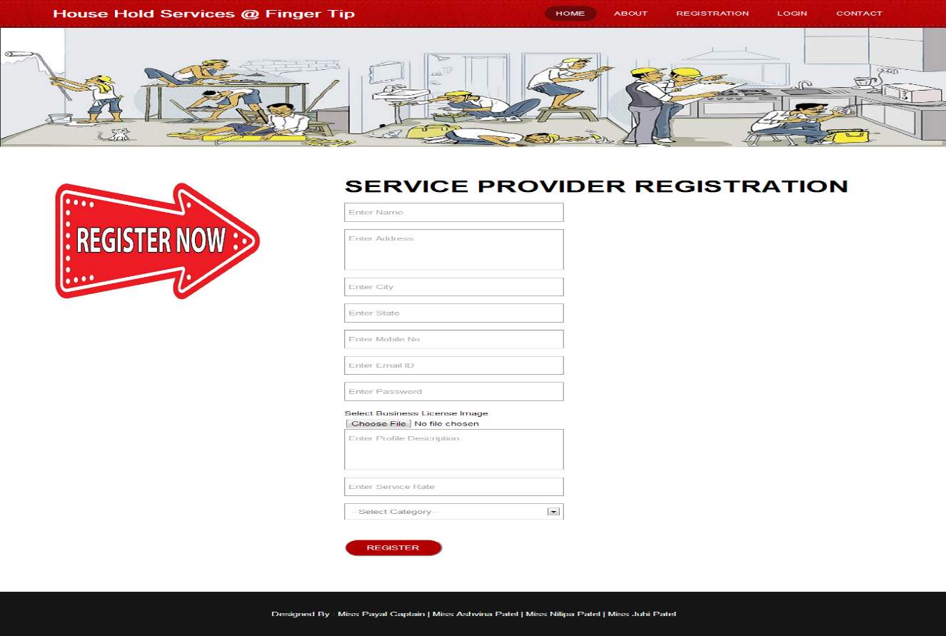
Service Provider Registration Page
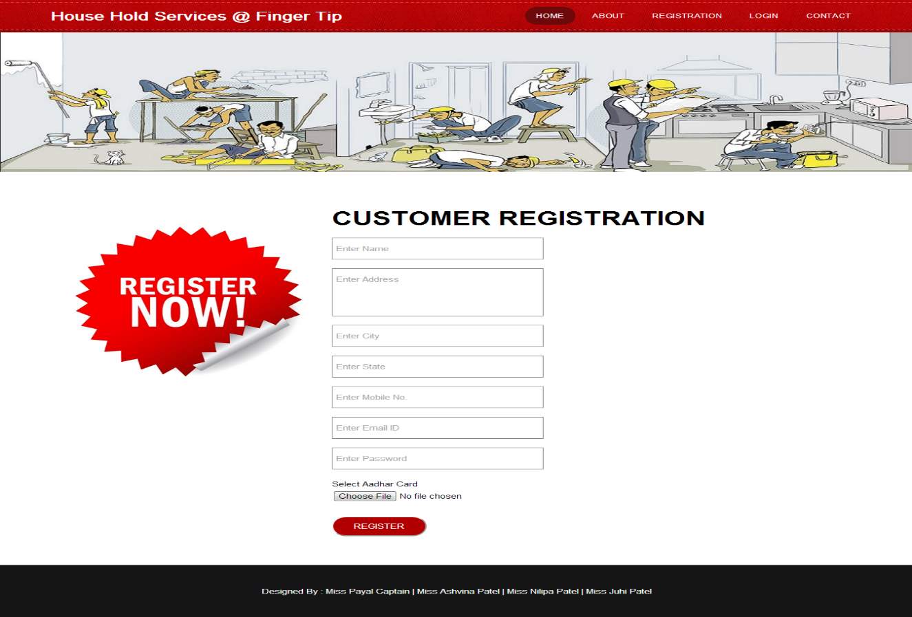
Customer Registration Page:
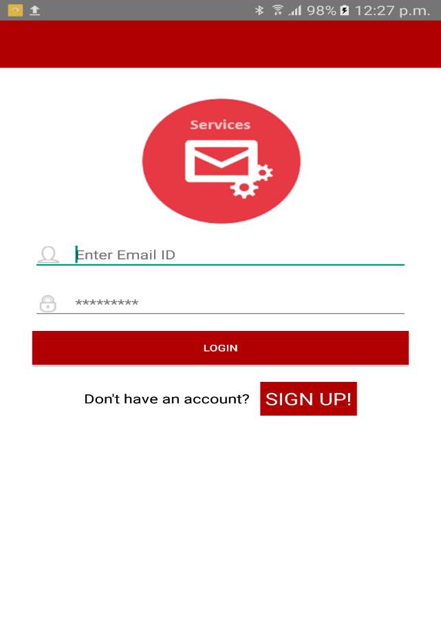
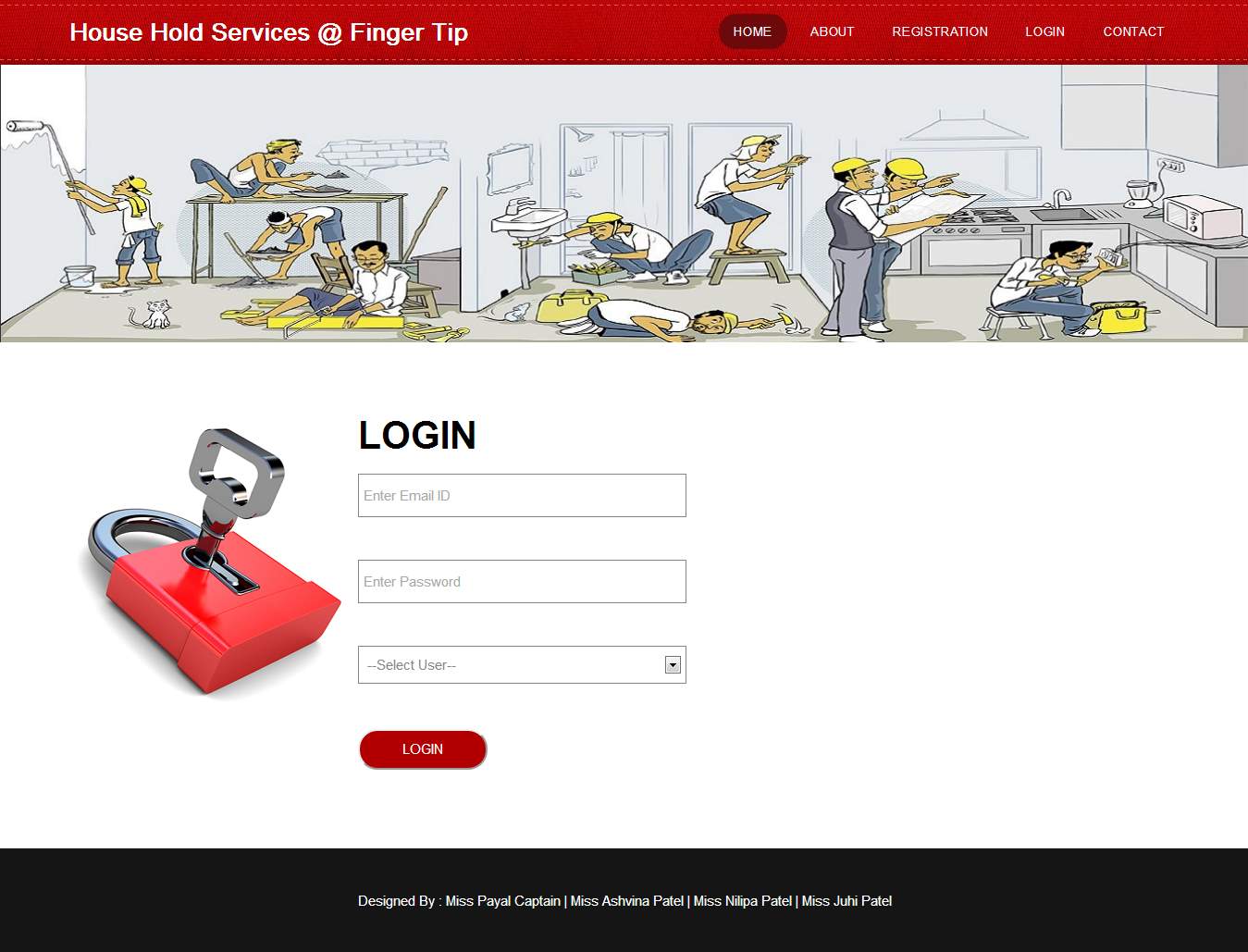
Login Page:
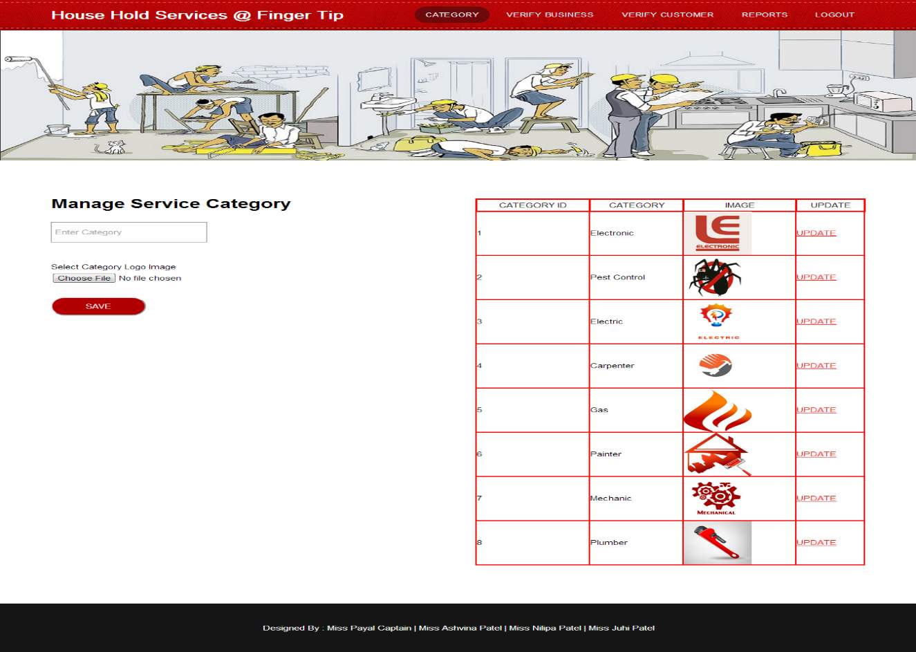
Manage Category
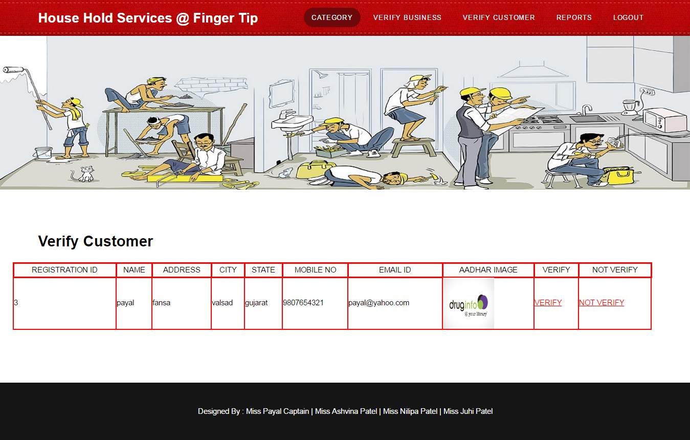
Verify Customer
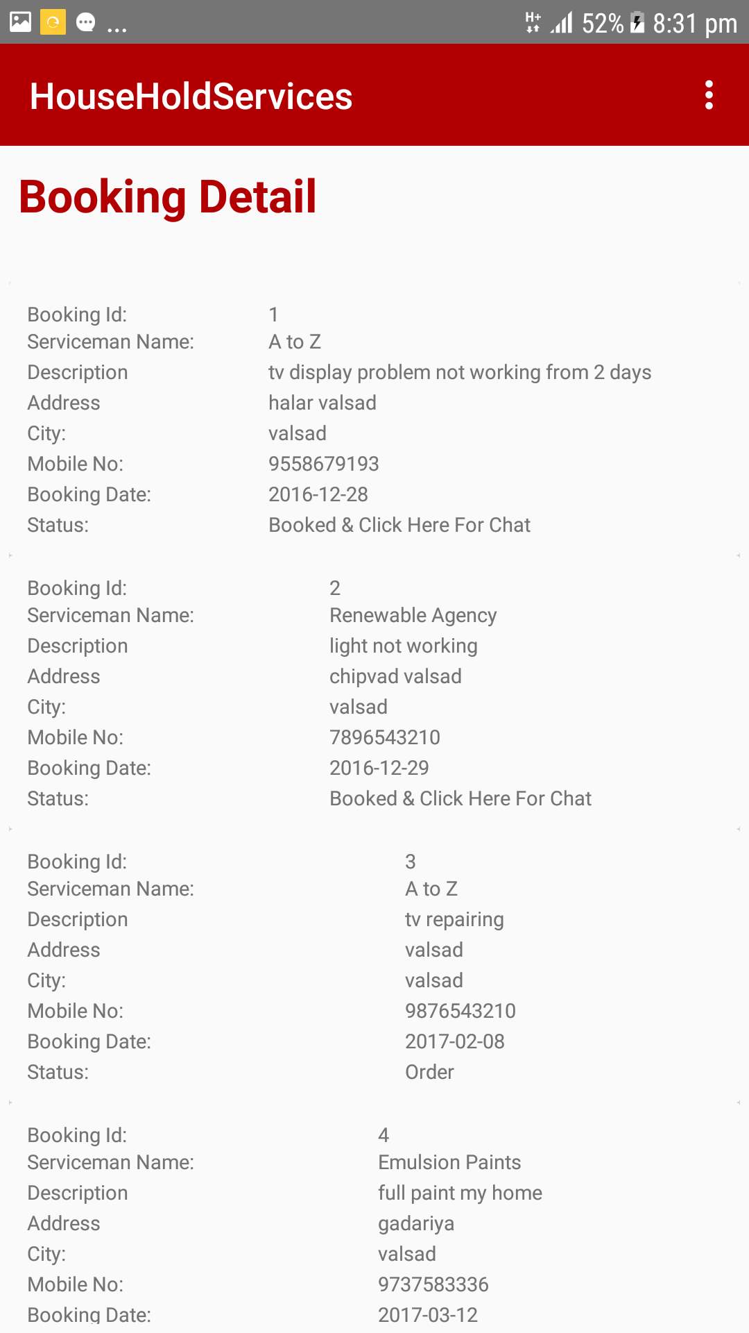
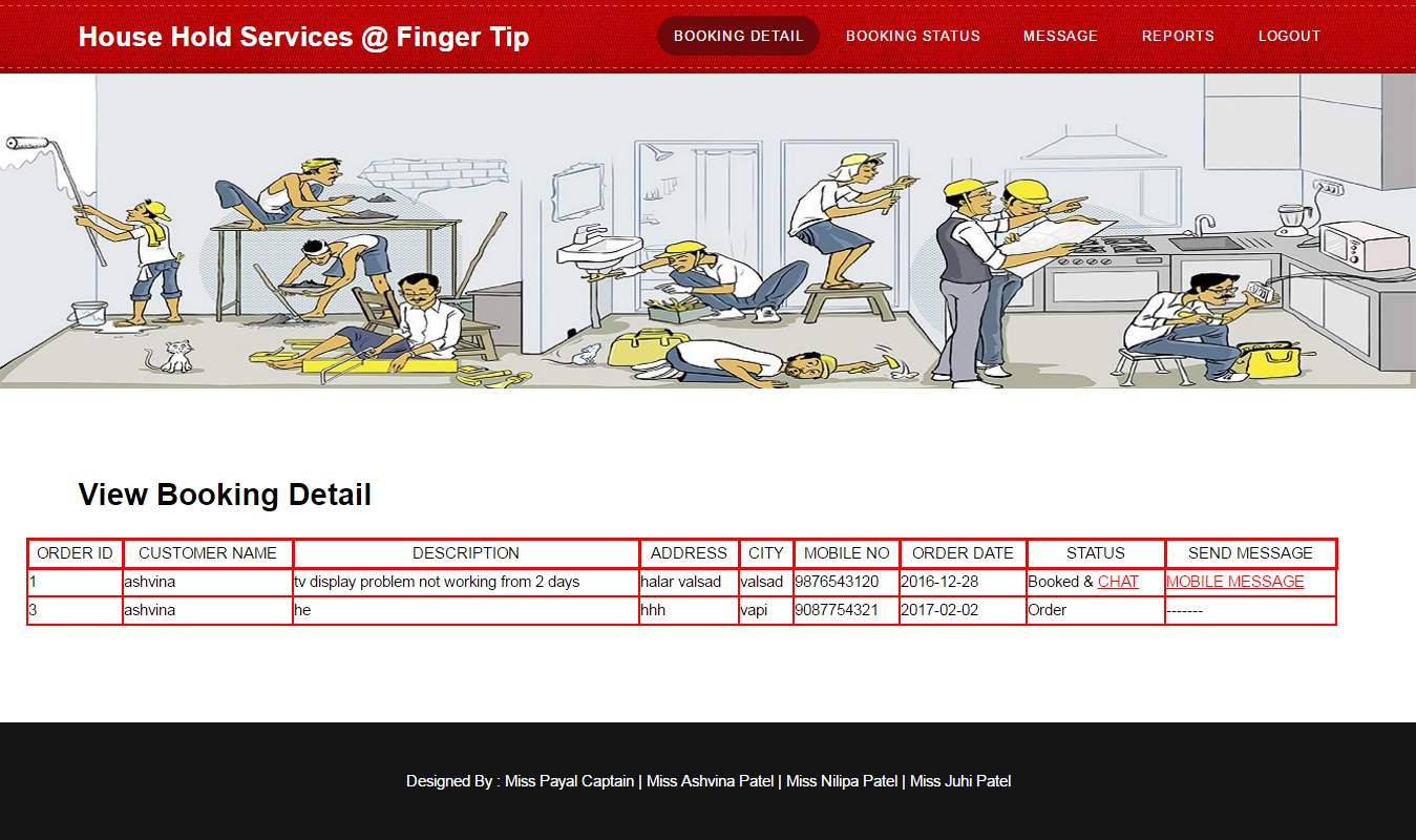
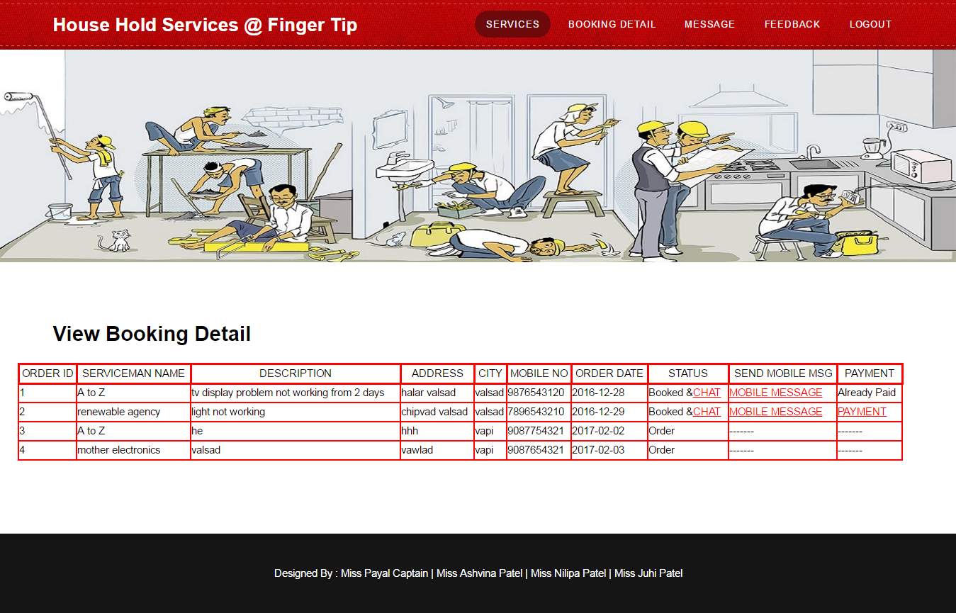
Booking Detail :
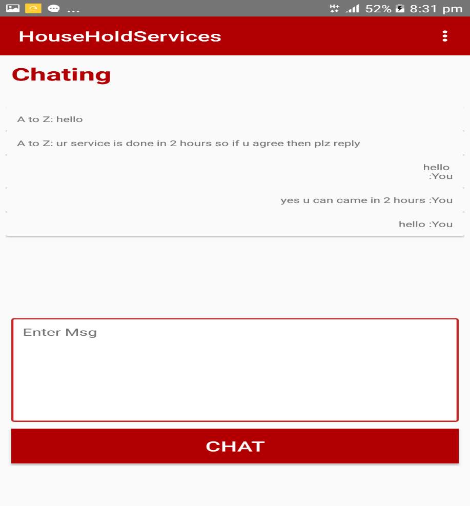
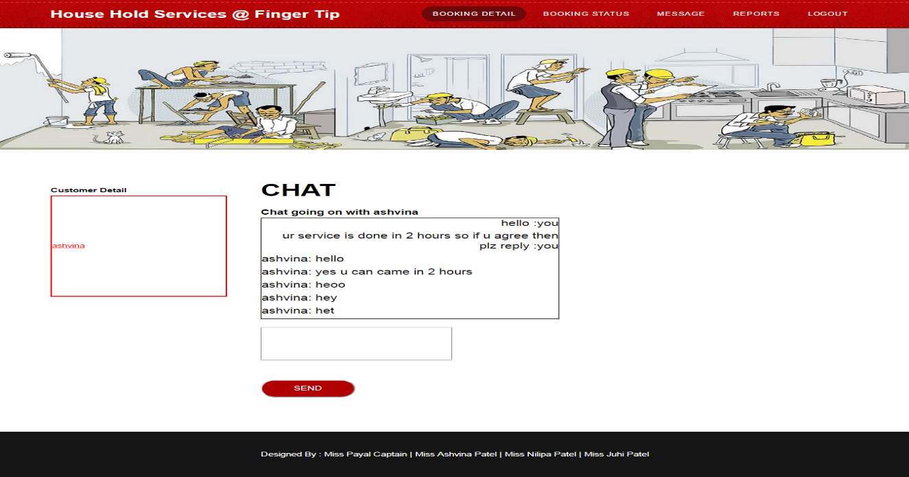
Chat :
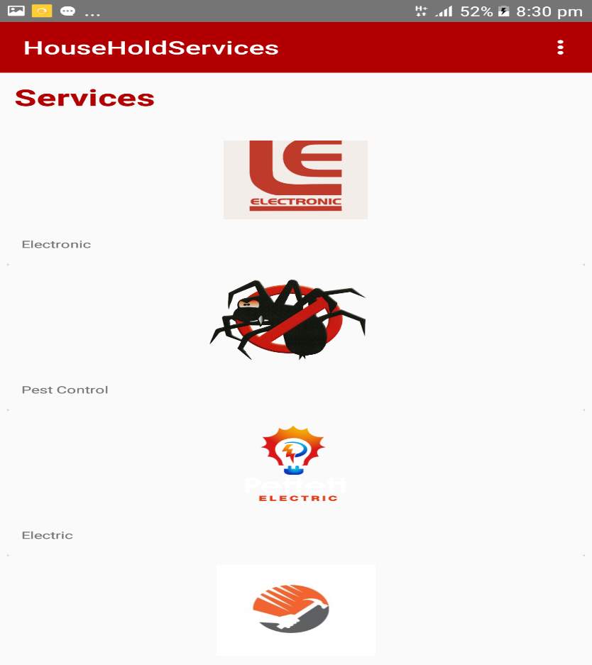
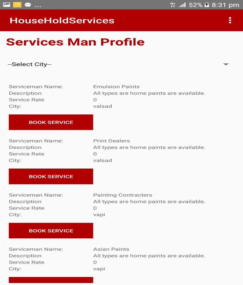
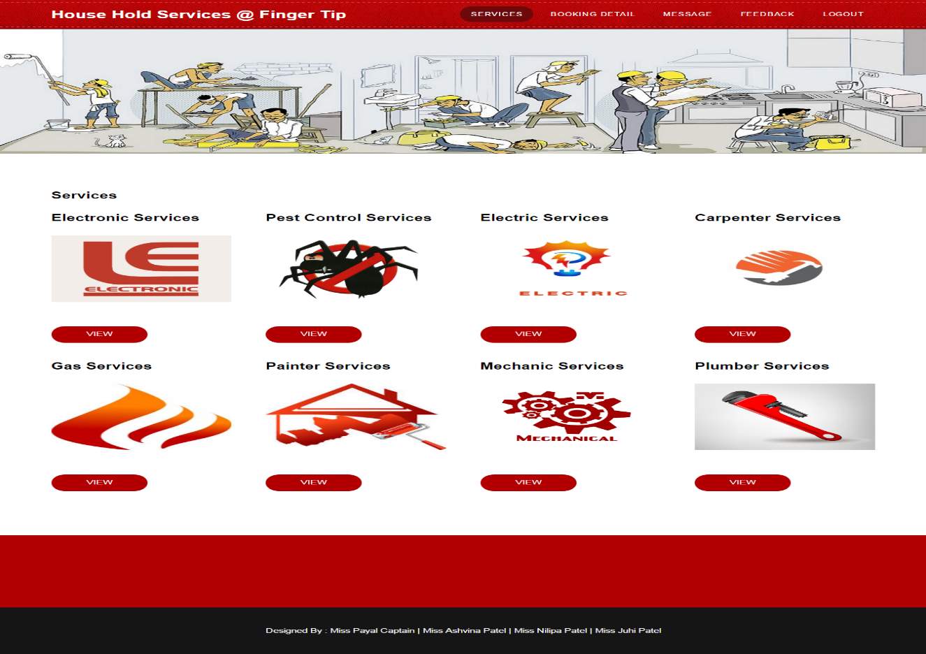
View Services Page :
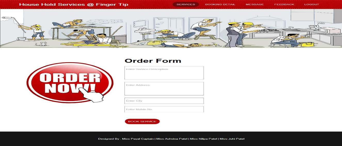
Order Form
Booking Detail Report :
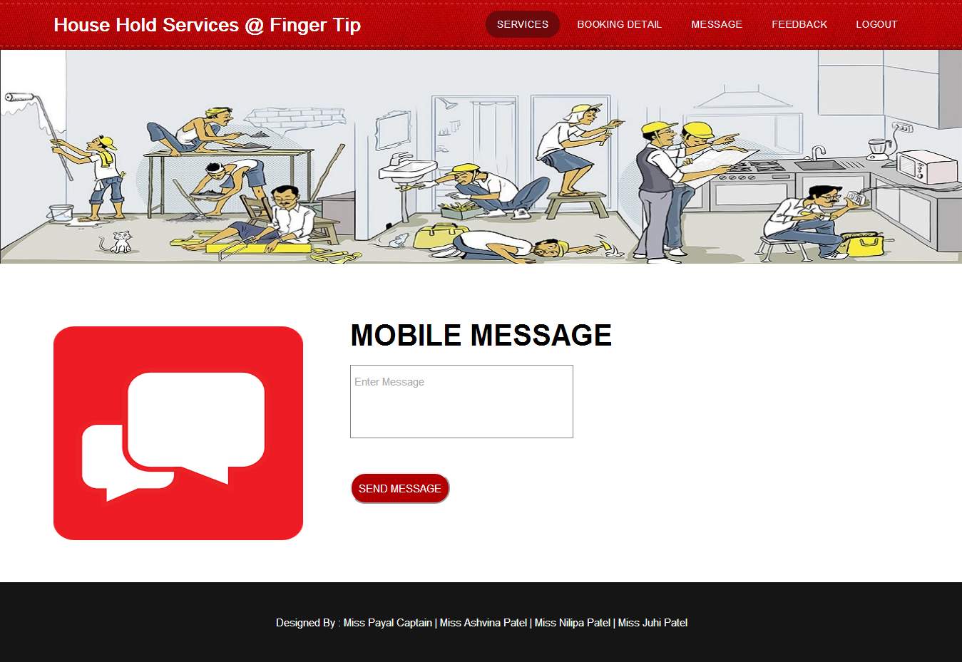
Mobile Message :
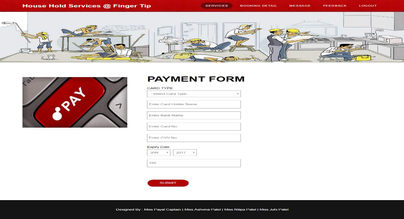
Payment page:
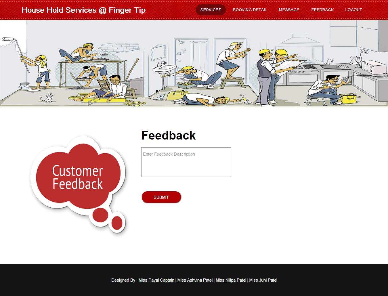
Feedback :
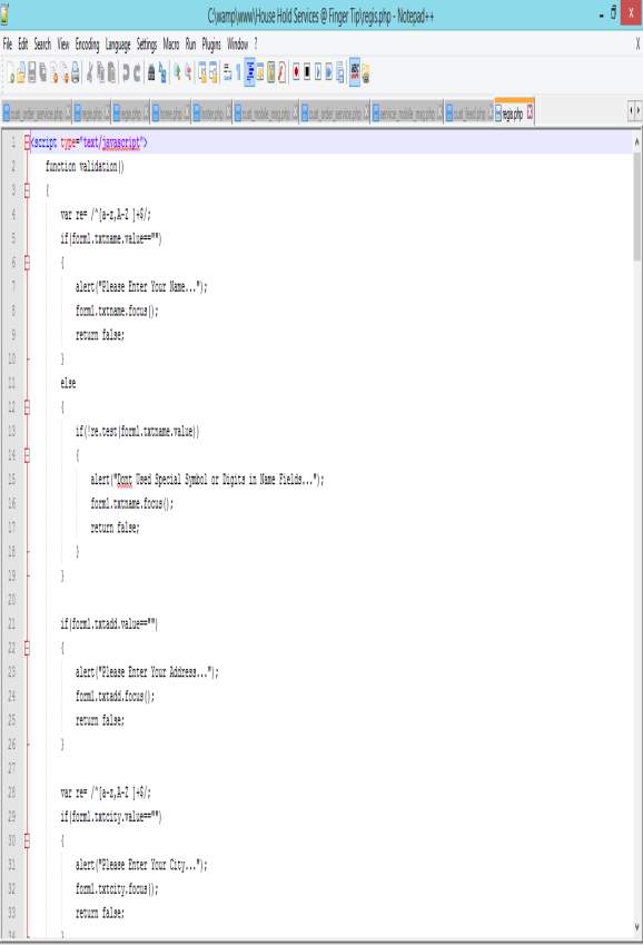
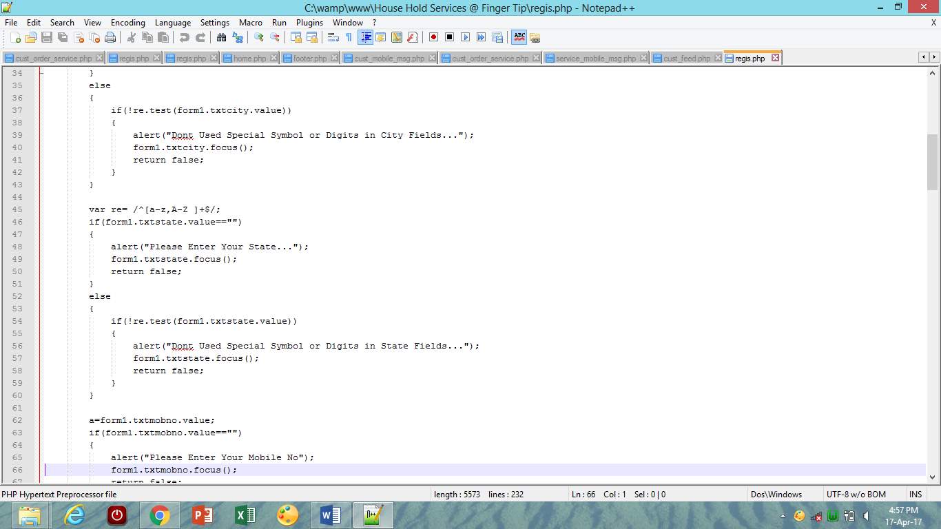
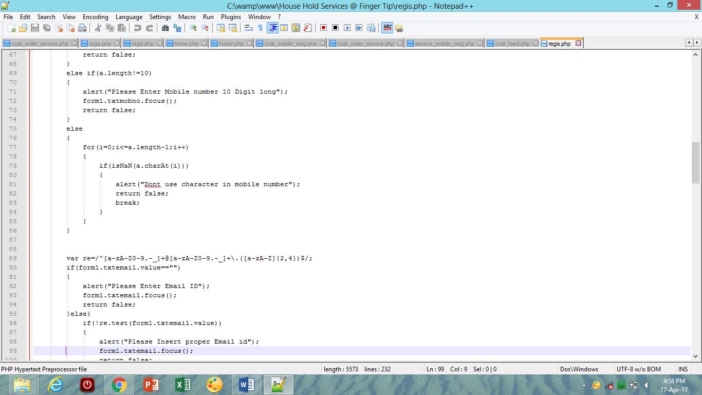
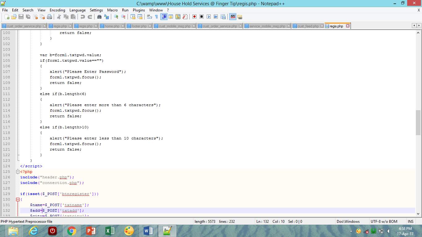
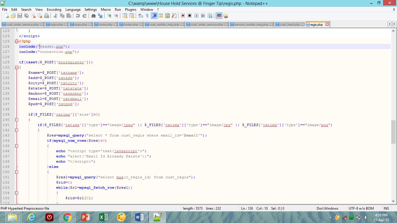
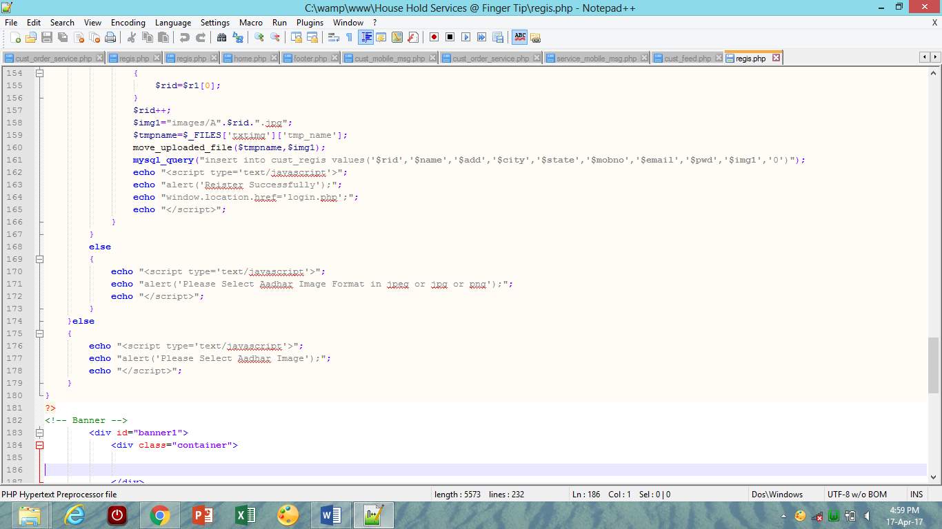
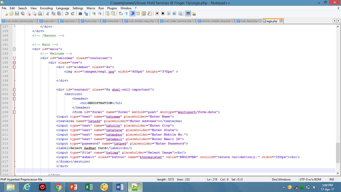
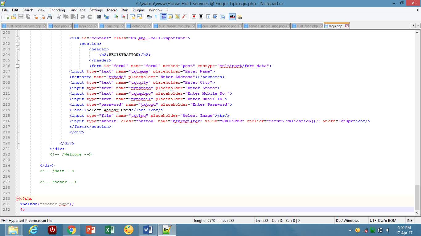
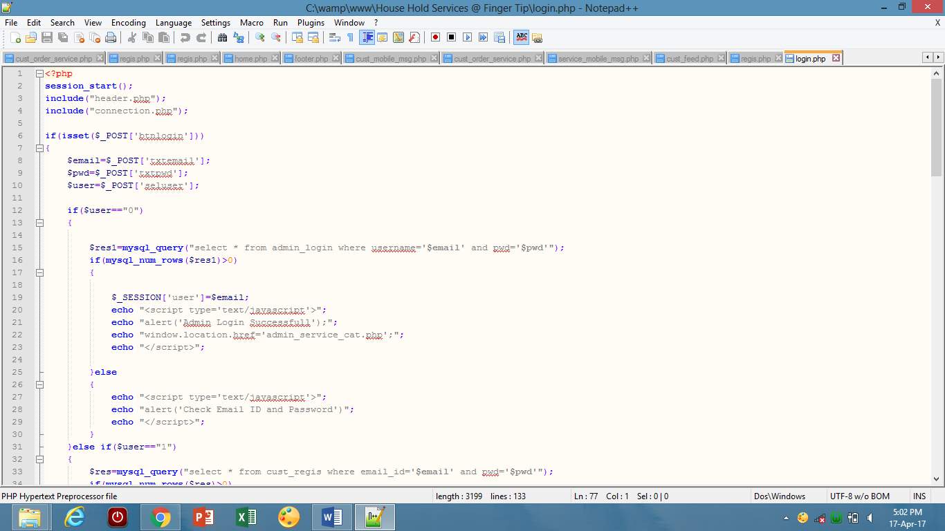
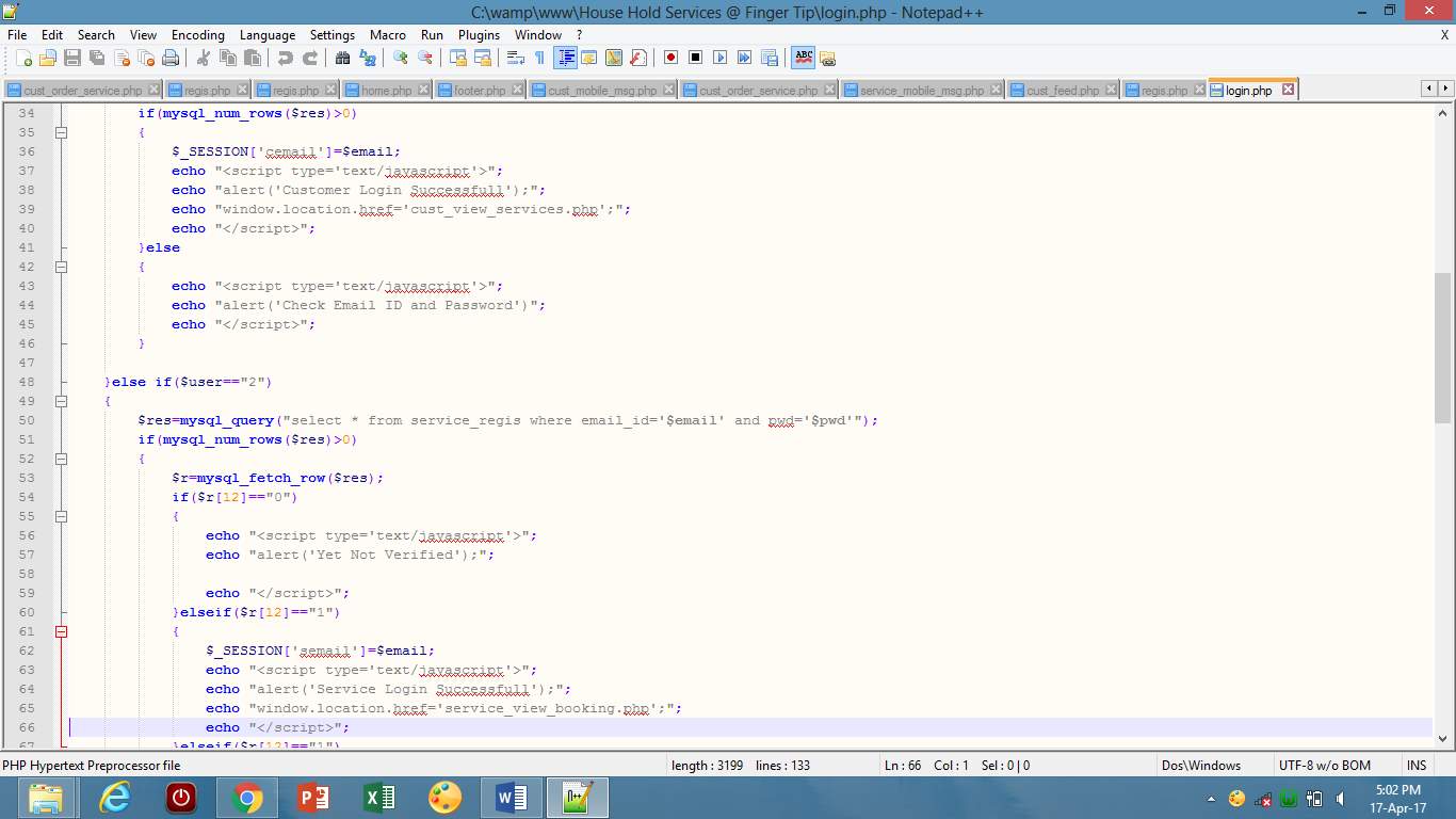
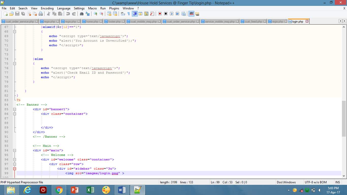
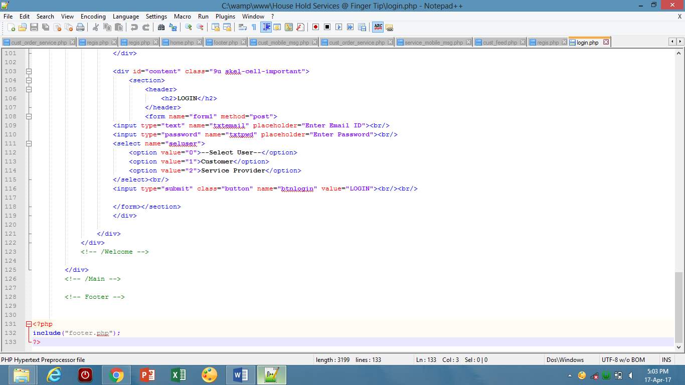
6.4 Sample Code
Registration page
Login page :
Chapter 7: CONCLUSION AND FUTURE WORK
Conclusion
An android application and website is developed which provide online service booking. The android application and website will provide a good user friendly interface for booking the services. It will give us security by generating QR code in the android application and website itself. It will provide notification so that the user keeps updated every time. It will provide the comments on feedback. Generating the QR code in the application itself will be more secured. No need of carrying print outs for proofs as the data is stored in the application itself. If the QR code is available with the user, the service provider will validate it by matching the QR code and if it is not available with the user, then that user is not valid.
Future work
In future we developed an android application and website in which we will put a map navigation for the service provider for find the location of user and the advertisement of shopkeeper where the shopkeeper can sell his equipment.
References
Websites:
[1] : https://www.canvs.in/
[2] : https://en.wikipedia.org/wiki/Service_%28economics
[3] : https://openfuel.org/
[4] : http://hservices.ca/
[5]: www.helpguru.com
[6] : www.justdial.com
[7] : https://patents.google.com/
Books :
For making UML diagrams:
[1] : Software Engineering by Roger S. Pressman
[2] : PL/SQL- by Steven Feuerstein
[3]: Software Engineering by Mrs. Anuradha A. Puntambekar
Cite This Work
To export a reference to this article please select a referencing stye below:
Related Services
View all


Related Content
All TagsContent relating to: "Technology"
Technology can be described as the use of scientific and advanced knowledge to meet the requirements of humans. Technology is continuously developing, and is used in almost all aspects of life.
Related Articles

DMCA / Removal Request
If you are the original writer of this dissertation and no longer wish to have your work published on the UKDiss.com website then please: