Analysis of Domain-specific Software Tools for Embedded System User Interface
Info: 12915 words (52 pages) Dissertation
Published: 11th Dec 2019
Tagged: Information SystemsInternet
Abstract
DSLs are languages used for solving problems in a specific domain. The adoption of DSL raise the level of abstraction from raw implementation code to the actual problem domain which in turn improves code readability and makes program integration easier. Embedded system software development rely on reusable components allowing developers to focus on the required variation between products to be developed. Domain-specific modeling tools and languages allow meticulous design, analysis and automatic code generation, improving system quality. Many tools exist in the space of domain-specific modeling, in this research we analyzed some of these tools for developing embedded system UI by developing an electronic price tag system with these tools. We recognized that some tools perform better than the other under different criteria we defined for them.
Contents
2.2 Traditional Software Engineering vs. DSE
3.3 Experience on Using DSL for Embedded System Development
DOMAIN-SPECIFIC MODELING TOOLS
4.1.1 Microsoft Visual Studio DSL Tools
4.1.3 Graphical Modeling Framework (GMF)
4.3 Approach to the development of our case study
5.2 Building EPTS with Microsoft Visual DSL Tools
5.2.1 Modeling the Domain Concept
5.2.2 Graphical Notation Description
5.3 Building EPTS with Obeo Designer
5.3.2 Graphical Notation Description
5.4 Building EPTS with GMF (Graphical Modeling Framework)
5.4.2 Graphical Notation Description
Table 1: Difference between GPL and DSL
Table 2: Criteria, domain and tool evaluated
Figure 1: Traditional SE vs. DSM
Figure 2: Programming with GPL
Figure 3: Programming with DSL
Figure 4:Example of Embedded System
Figure 5: Microsoft Visual Studio DSL Tools Interface Description
Figure 6: Obeo Designer Interface
Figure 8: Electronic Price Tag System Architecture
Figure 9: DSL Development Phases
Figure 10: Steps in Creating DSM Solution in MS DSL Tools
Figure 11: Diagram Description In MS DSL Tools
Figure 12: Steps in Using Obeo Designer
Figure 13: Ecore Model for Electronic Price Tag System
Figure 15: GMF graphical definition model
CHAPTER ONE
1.0 Introduction
This chapter aim to introduce the study area, providing the motivation and our objectives. This chapter is structured as follows: Section 1.1 presents the background to this study. Section 1.2 presents the motivation for this work. Section 1.3 defines the research objectives. Section 1.4 describes the approach taken to achieve the objectives. Section 1.5 presents the structure of this report. Section 1.6 presents meanings to acronyms used throughout this research.
1.1 Background
A Domain-Specific Language is a custom language that targets a small problem domain, which it describes and validates in terms native to the domain (Cook S., 2008). DSLs are languages used for solving problems in a specific domain. They are languages of limited expressiveness which allows for increase productivity and reduce maintenance. They have close relationship to the problem domain and concept than GPL and modeling language. DSL is a software solution that allows the domain experts to spend their time more effectively describing or solving a problem as opposed to battling with a programming language.
A domain can range from compilers for programming languages, consumer electronics, electronic commerce system/web stores, video game, and business applications.
A domain model identifies fundamental business- and application-specific entity types and relationships between them, including business processes (Broy, 2013). Thus any SE project involves one or more domains that should be identified and precisely defined as languages. Furthermore, tools are required in order to engineer domain artefacts and tool definition should be part of the domain engineering process. Once a precise requirement for a DSL tool is available, a project is in a position to find the most appropriate way of providing the tools and their associated languages. This approach can lead to a specification for a project-specific tool suite that supports domain-specific languages (Tony Clark, 2013).
Domain-Specific Modeling (DSM) improves current software development approaches in two ways. First, it raises the level of abstraction beyond programming by specifying the solution in a language that directly uses concepts and rules from a specific problem domain — a Domain-Specific Language (DSL). Second, it generates fully functional production code from these high-level specifications(Steven Kelly, 2008).
Over the years, strong interest in DSL has brought about evolution of tools for DSM. Although, DSL tools and code generators have been around for a while but many developers using DSLs have chosen to implement their own code generators with varying degrees of success.
More recently, DSL tools with customizable modeling languages and code generators have emerged. These tools provide built-in support for both defining the DSM environments and applying them in product development.
1.2 Motivation
Embedded system require rigorous design modeling, consumers now rely on and expect the ease and convenience of intelligent embedded systems. Over the years, there has been a significant increase in the use of embedded software, traditional software development been proven manageable to an extent but embedded system development has not been able to prove much to that degree. There is repeated need to improve the user interfaces of embedded systems software.
The next wave of successful electronics demands streamlined, intuitive and easy-to-operate user interfaces that leverage the latest touch technology and hardware interfaces—without slowing the development process or increasing costs of goods (Clarke, 2012).
With the revolution of touchscreens and sophisticated user interfaces, embedded software developers have been quick to recognize these new way to interacting with technology and embedded device user interfaces have become much more than just a simple buttons, LEDs or control panels. Hence, the need to analyze the tools for developing user-friendly embedded software user interface.
Reliance on software system to perform operations has called for increase in productivity, reduced maintenance and programming expertise which DSL brings with it in its application in developing software system. The sooner the gap between problem domain and solution domain is bridged, the better.
1.3 Aim and Objectives
The purpose of this study is to outline a systematic approach to the design of embedded system user interface using the DSM approach, which includes certain models, methods and tools for embedded system in the ESS domain. The research objectives is as follows;
- To ensure development of reliable yet intuitive user interface for embedded software
- To analyze tools for developing embedded system UI so as to improve productivity and reduce error in embedded software.
- Generate software artefacts for embedded ESS system
- Work on full tool flow and present it in the result
- To allow domain experts to focus on the design decisions relevant to the domain and use the most suitable concepts and abstractions
- provide a road map to domain expert in the embedded software development domain so as to help in deciding which DSM tool best suite their embedded system software development and to further boost productivity
1.4 Methodology
The project set out to perform analysis of some selected DSL Tools for embedded system user interface development. We are going to give an overview of embedded system in ESS domain. Some DSM tools would be studied and these tools will be used to generate software artefacts. We then compare experience gained in the generation of our software artefacts using these tools based on a set of evaluation criteria and result will be presented regarding advantages and drawbacks of each DSM tool. The comparison will be performed based evaluation criteria that will be discussed in later chapters.
This research work aim to provide a road map to domain expert in the embedded software development domain so as to help in deciding which DSM tool best suite their embedded system software development and to further boost productivity in which DSM has brought with it in use for software development.
1.5 Report Structure
The aim of this section is to give a brief overview about the chapters in this research. Each chapter has different focus and scope. This report is further structured as follows:
Chapter 2: presents an overview of DSL, its benefits, challenges of using of using DSL in development and comparison of DSM in its’ use with traditional software development methodology and also its comparison with UML. In addition, we discussed about tooling support of DSM.
Chapter 3: presents overview of embedded system, it discusses the state-of-the-art implementation scenarios of embedded system. This chapter also present IoT and how they are exploring embedded system development and re-introducing embedded software development to the world. We also look at some embedded systems software in the ESS domain.
Chapter 4: we discussed some DSM tools and we also present our case study – electronic price tag system and discuss in details how this works. We also discuss DSL development phases.
Chapter 5: We choose three (3) DSM tools for evaluation based on reviews done and we used these tools to develop our case study and explain this tools. More so, we evaluate these tools based on a set of criteria by using this tools to generate software artefacts with regards to the previously formulated requirements for our case study and we present our result
Chapter 6: we present previous research works directed towards DSM and discusses how these correspond to the author’s work and how they have motivated us to conduct this research.
Finally, we present our conclusions and give directions for further research.
1.6 Abbreviations
| Acronym | Definition |
| DSL | Domain-Specific Language |
| ERP | Enterprise Resource Planning |
| DSM | Domain-Specific Modeling |
| MPS | Meta Programming System |
| UML | Unified Modeling Language |
| Microsoft VS/DSL Tools | Microsoft Visual Studio DSL Tools |
| ESS | Enterprise System Software |
| EPTS | Electronic Price Tag System |
| GMF | Graphical Modeling Framework |
| DSE | Domain-Specific Engineering |
CHAPTER TWO
DOMAIN-SPECIFIC MODELING
2.1 Domain Specific Language
DSL aim to raise the level of abstraction in which domain expert and software developers can program and also provide domain-specific abstraction. It contains the syntax and semantics that model concepts at the same level of abstraction that the problem domain offers (Debasish, DSLs in ACTION, 2011).
Domain-specific development is the process of identifying the parts of your applications that can be modeled by using a domain-specific language, and then constructing the language and deploying it to the application developers. The developers use the domain-specific language to construct models that are specific to their applications, use the models to generate source code, and then use the source code to develop the applications (Microsoft). In Domain-Specific Development, instead of building on a general-purpose language in order to solve a problem, we use a language that is itself designed to suit the problem being solved (Cook S., 2008). DSM requires an adequate knowledge of the problem domain. Examples of domain-specific languages are; SQL, YACC, Cryptol, Postscript, BNL, HTML, CSS, Hibernate, Groovy, OpenGL/DirectX, etc.
According to (Steven Kelly, 2008)Domain-Specific Modeling allows faster development, based on models of the problem domain rather than on models of the code. Industrial experiences of DSM show major improvements in productivity, lower development costs and better quality and the key factors contributing to this are:
- The problem is solved only once at a high level of abstraction and the final code is generated straight from this solution.
- The focus of developers shifts from the code to the design, the problem itself. Complexity and implementation details can be hidden, and already familiar terminology is emphasized.
- Consistency of products and lower error-rates are achieved thanks to the better uniformity of the development environment and reduced switching between the levels of design and implementation.
- The domain knowledge is made explicit for the development team, being captured in the modeling language and its tool support.
2.1.1 Types of DSL
There are two types of DSL as describe by (Fowler, 2005)
- Internal DSL: Internal DSLs An internal DSL is one that uses the infrastructure of an existing programming language (also called the host language of the DSL) to build domain-specific semantics on top of it. In most cases, an internal DSL is implemented as a library on top of the existing host language (Debasish, DSLs in ACTION, 2011). Example of this is Rail.
- External DSL: An external DSL is one that’s developed ground-up and has separate infrastructure for lexical analysis, parsing techniques, interpretation, compilation, and code generation. Developing an external DSL is similar to implementing a new language from scratch with its own syntax and semantics (Debasish, DSLs in ACTION, 2011). The advantage of an external DSL for a user programmable DSL is that you can drop all the baggage of your host language and present something that’s very clear for the user (Fowler, 2005).
2.1.2 Benefits of DSL
- Increased Productivity: Increased Productivity: It allow programmers to develop their applications faster since the solution is based on the model of the product and not the code. Adoption of DSL in industry have been proven to increase productivity, development costs and better quality.
- More concise: Idea about the problem domain is adequately represented.
- Easier to maintain: For applications written in DSL, changing architecture will only involve the compiler or interpreter to be modified to obtain a full conversion.
- Model created can be used for documentation and also they can be transformed into other software artefact (source code etc.).
- Easier to reason about
- Greater reliability in applications: A DSL compiler may effectively prevent the construction of incorrect or unsafe object programs. A DSL may also be designed to support the validation of desirable properties at the domain level, which is usually a lot simpler than verifying code in a general-purpose programming language.
- DSM does not require knowledge of programming rather a domain expert before model can be created to generate software artefacts. This helps bridge the gap between developer and user.
2.1.3 Challenges of Using DSL
- Designing, implementing and maintaining a DSL can be so expensive;
- The costs of education for DSL users is high;
- The limited availability of DSLs;
- The difficulty of finding the proper scope for a DSL;
- The difficulty of balancing between domain-specificity and general-purpose programming language constructs;
- The potential loss of efficiency when compared with hand-coded software.
2.2 Traditional Software Engineering vs. DSE
In developing complex software systems, much manual and routine work has to be performed in order to get a software product. Traditional software development involves starting the solution from scratch – manually writing code from ground up. Re-inventing the wheel is always the case and manually writing the code every time seems infeasible.
A traditional approach to software development using GPL provides a general solution for many problems in a certain area which may sometimes be of poor quality. A specific approach provides a much better solution for a smaller set of problems.
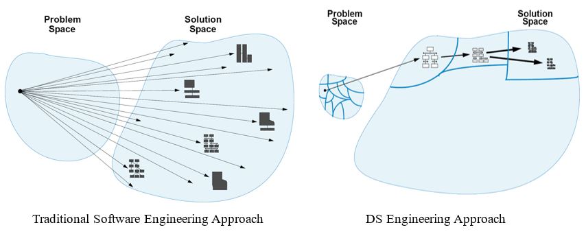
Figure 1: Traditional SE vs. DSM
In DSM, solution is built from idea of the problem domain by developer or domain expert. It contains the syntax and semantics that model concepts at the same level of abstraction that the problem domain offers.
Table 1: Difference between GPL and DSL
| GPL | DSL | ||
| 1. | Domain Size | Large and complex | Well-defined, smaller |
| 2. | Developed by | Designed by expert | Developed by domain expert |
| 3. | Turing completeness | Mostly Turing-complete | Not Turing-complete |
| 4. | User Community | Large and ever-growing community | Small and accessible community |
| 5. | In-language Abstraction | Complex low-level abstraction | Limited, high-level abstraction |
| 6. | Lifespan | Years/Decade | Months to years |
| 7. | Evolution | Slow | Fast |
| 8. | Language Size | Large | Small |
When programming in GPL, there is a wide gap between the solution to a problem and when to successfully communicate the solution to the computer as a program. Considerable amount of time is spent looking for ways to represent natural language concepts in terms of programming level of abstractions, this process is time-consuming and requires more effort as shown in Fig 1 and 2 below.
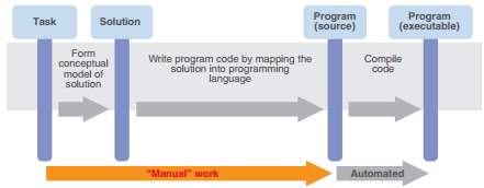
Figure 2: Programming with GPL
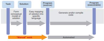
Figure 3: Programming with DSL
2.3 UML vs. DSL
Any plan to standardize a general-purpose model or set of models will likely continue to fail because humans inherently need to express their own creativity (Not Invented Here [NIH] syndrome) (Gronback, 2009).
UML is a generic modeling language that lets you describe software architectures, software interactions and other aspects of software structure. UML is used for modelling systems that can also be represented by general-purpose programming languages and can also be used for generating source code in GPL. General-to-general mappings typically don’t work well, so additional specificity is typically applied at one end or both ends (Gronback, 2009).
DSLs are specialized syntaxes meant to make it easier to proffer solutions to problem in a specific domain by giving domain-expert/developer ability to generate software artefacts from high-level abstraction. The tight fit with the problem domain, high level of abstraction, precision, and ability to use with customers are clear areas where DSLs excel over generic languages like UML (Blake, 2007).
2.4 Tooling Support
Over the years, strong interest in DSL has brought about evolution of tools for DSM. Although, DSL tools and code generators have been around for a while but many developers using DSLs have chosen to develop their own code generators with varying degrees of success.
More recently, DSL tools with customizable modeling languages and code generators have emerged. These tools provide built-in support for both defining the DSM environments and applying them in product development.
They provide GUI frontend, metamodeling and/or code generation to define and use of DSL. They usually contains toolbox which consist of diagrams, shapes and connectors, design surface, model explorer, solution explorer e.g. Eclipse Modeling Project, Meta Edit+, Microsoft Visual Studio DSL Tools, GMF, JetBrains Metaprogramming System, GME (Generic Modeling Environment), Obeo Designer, etc.
CHAPTER THREE
EMBEDDED SYSTEM
3.1 Embedded System
An embedded system is a computer system with a dedicated function within a larger mechanical or electrical system, often with real-time computing constraints. Embedded systems can be system with minimal or no UI, systems whose function is to perform only one task or systems with complex graphical user interfaces that resemble modern computer OS. Simple embedded devices use buttons, LEDs, graphic or character LCDs with a simple menu system.
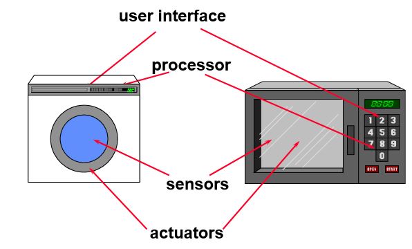
Figure 4:Example of Embedded System
Embedded software development rely on reusable components allowing developers to focus on the required variation between products to be developed. DSM allow rigorous analysis, design, implementation and software artefacts generation, thereby improving the quality of system developed.
3.2 Impact of IoT on ERP
Internet of Things (IoT) refers to the embedding of sensors and computing devices into physical “things” that traditionally haven’t had any kind of connectivity, such as a light bulb, an infant’s pajamas, or even a cow. The things are then connected to wired or wireless networks, giving them the ability to communicate with one another, other systems, users, and/or manufacturers. Essentially, the IoT is a bridge between the physical world and the digital world (AbasERP, 2015 ).
As interest in the Internet of Things and mobile devices continues to grow, companies are recognizing the value of embedded systems to collect data and control machinery. From software in cars and trucks to mobile medical devices and home appliances like refrigerators and even toothbrushes, embedded applications are permeating our world (Freudenthal, 2010). As ESSD’s ambition is to integrate all units and functions across a company onto a single computer system that can serve all those different departments’ particular need, user-centered improvement in software development will not only improve productivity but also reduce maintenance.
3.3 Experience on Using DSL for Embedded System Development
Domain-Specific Language have been employed in complex software development and it has been proved to increase productivity.
- Touch Screen Controller (Lifinity): (Tolvanen, 2014) reported that Lifinity is a touch screen device that is used to control lights, heating, air-conditioning, and burglar and other alarms developed by Panasonic. Language definition of the DSM solution defined was restricted to cover user interface application with the author citing 60% – 80% contribution to the framework. Panasonic define DSL with the generator that transform them into artifacts the company needed, supported by a tool that provide the functionalities needed. They measure development effort by comparing their current manual approach with the new DSM solution implemented with this showing 300% – 500% increase.
- Sport Computer: (Tolvanen, 2014) stated that Sport Computer is a product that measure, analyze and visualize data on measures like heart rate, calories, speed, distance, altitude changes, pedaling rate and cycling power developed by Polar. Their features depend on the product segment and the type of sports the product is designed for, such as cycling, fitness and team sports. DSM solution created by Polar covers only the UI application side with the author citing 40% – 50% contribution to development time, noting that improvement to the UI development will improve the overall development time. The influence of DSM was evaluated in two different ways by Polar; first by building a large portion of a product in a pilot project and secondly asking 6 developers to individually implement a small but typical feature. Comparing the development time in the first case, it was discovered that the development time with ordinary approach was 23days and 2.3days with DSM approach. In the second category – a controlled experiment of smaller task, implementation with ordinary approach would take up to 16hours but took up to 75minutes to 125minutes with DSM approach which boost over 900% productivity improvement.
CHAPTER FOUR
DOMAIN-SPECIFIC MODELING TOOLS
4.1 DSM Tools
In recent years, external DSL as evolved to visual DSL which are used mainly for DSM that make use of graphical notations and/or text. More DSM tool vendors have been developing “language workbench” that will aid faster development with DSL.
The tables below depict some selected previous research and the various tools, criteria and other factors employed by the various authors to evaluate DSL.
Table 2: Criteria, domain and tool evaluated
| Author (s), Title, Year | Criteria for Evaluation | Domain Evaluated | Tool Used/Evaluated | |
| 1. | Daniel Amyot, Hanna Farah, and Jean-Franc¸ois Roy. Evaluation of Development Tools for Domain-Specific Modeling Languages. 2006 | Graphical completeness, editor usability, effort, Language evolution, Integration, analysis capabilities | Model Engineering | GME, Tau G2, RSA, XMF-Mosaic, Eclipse |
| 2. | Juha-Pekka Tolvanen. Industrial Experiences on Using DSLs in Embedded Software Development. 2014 | Productivity, effort | Industrial Embedded System (UI application side) | MetaEdit+ Workbench |
| 3. | Margus Freudenthal. Using DSLs for Developing Enterprise Systems. 2010 | Maturity, support, availability | Enterprise Systems | ANTLR and StringTemplate, Stratego/XT, Xtext, IMP, Meta Programming System |
| 4. | Michael Pfeiffer and Josef Pichler. A comparison of tool support for textual domain-specific languages. 2008 | Language style, transformation, tool assistance | None | openArchitectureWare (oAW), Meta Programming System (MPS), MontiCore, IDE Meta-Tooling Platform (IMP), Textual Concrete Syntax (TCS), Textual Editing Framework (TEF), CodeWorker |
| 5. | Philip De Smedt – Comparing three graphical DSL editors: AToM3, MetaEdit+ and Poseidon for DSLs, Elsevier, 2011. | Transformation tool, API, Abstract Syntax, Concrete Syntax, Binding between AS and CS, Relationships, Constraints | Embedded System (Traffic Simulation) | AToM3, MetaEdit+ and Poseidon |
| Author (s), Title, Year | Popularity | Maturity | Tool Application | Application (In Embedded System) | Heterogeneity of Tools Used | |
| 1. | Daniel Amyot, Hanna Farah, and Jean-Franc¸ois Roy. Evaluation of Development Tools for Domain-Specific Modeling Languages. 2006 | ~ | ~ | + | – | + |
| 2. | Juha-Pekka Tolvanen. Industrial Experiences on Using DSLs in Embedded Software Development. 2014 | + | + | + | + | – |
| 3. | Margus Freudenthal. Using DSLs for Developing Enterprise Systems. 2010 | + | + | – | – | + |
| 4. | Michael Pfeiffer and Josef Pichler. A comparison of tool support for textual domain-specific languages. 2008 | ~ | ~ | – | – | + |
| 5. | Philip De Smedt – Comparing three graphical DSL editors: AToM3, MetaEdit+ and Poseidon for DSLs, Elsevier, 2011. | ~ | ~ | + | + | + |
4.1.1 Microsoft Visual Studio DSL Tools
Domain-Specific Language Tools (DSL Tools), which are hosted in Visual Studio, let you design a domain-specific language and then generate everything that users must have to create models that are based on the language (Microsoft). Through the DSL Tools, one can create, edit and visualize metadata that is underpinned by a code framework, which makes it easier to define domain-specific schemas for metadata, and then to construct a custom graphical designer hosted in Visual Studio (André W. B. Furtado, 2002).
Microsoft DSL Tools consist of the following;
- A project wizard that uses different solution templates to help you start developing your domain-specific language.
- A graphical designer for creating and editing your domain-specific language definition.
- A validation engine that makes sure that the domain-specific language definition is well-formed, and displays errors and warnings if there are problems.
- A code generator that takes a domain-specific language definition as input and produces source code as output.
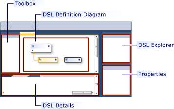
Figure 5: Microsoft Visual Studio DSL Tools Interface Description
4.1.2 Obeo Designer – Sirius
Obeo Designer guarantees the set up and the deployment of industrial-strength Modeling Workbenches created with Sirius. It provides professional support and collaborative features. Modeling workbenches created with Obeo Designer are composed of a set of editors (diagrams, tables and trees) which allow the users to collaboratively create and edit models in a shared repository.
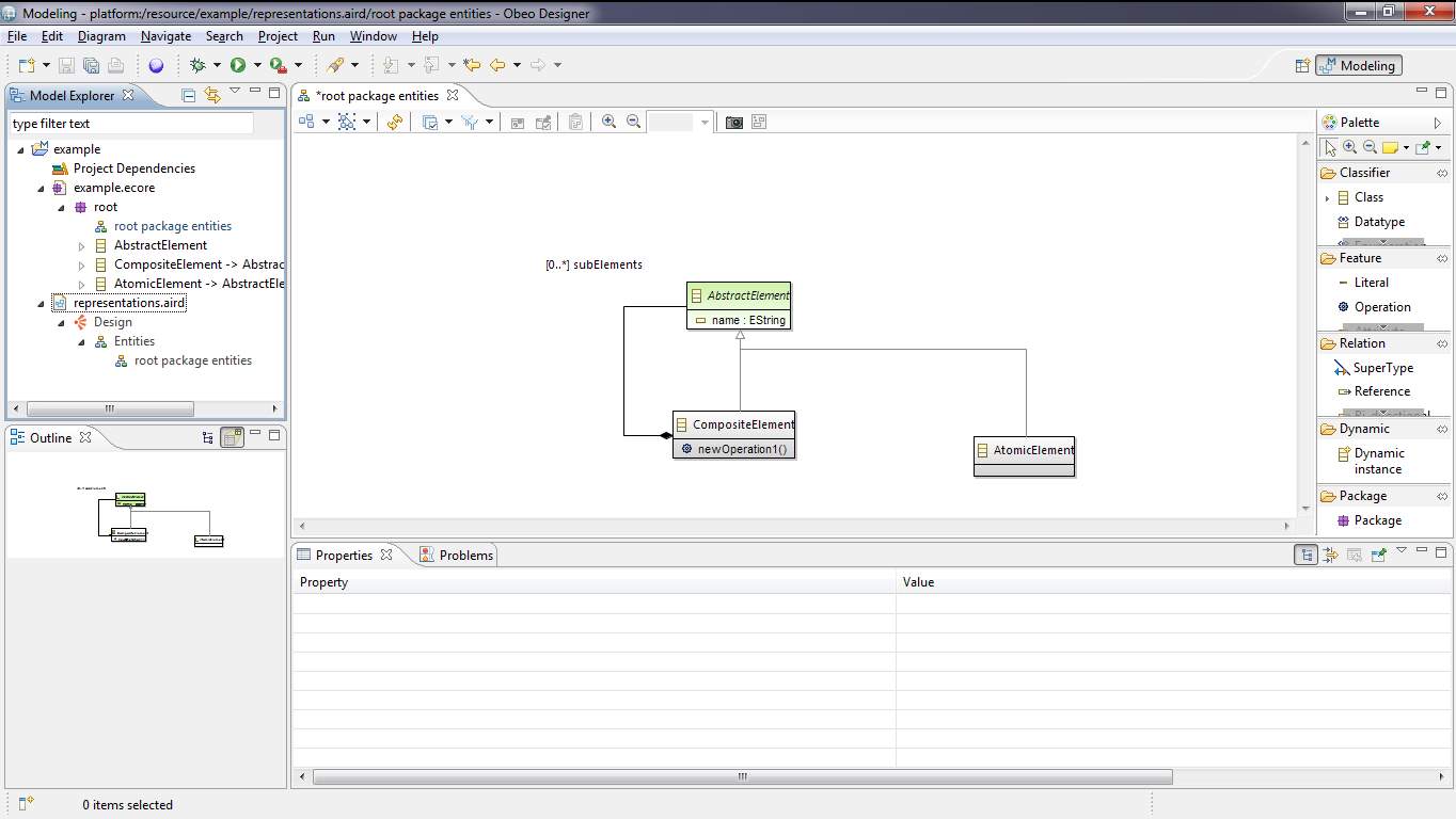
Figure 6: Obeo Designer Interface
Sirius is an Eclipse project which allows you to easily create your own graphical modeling workbench by leveraging the Eclipse Modeling technologies, including EMF and GMF (Sirius).
4.1.3 Graphical Modeling Framework (GMF)
The Eclipse Graphical Modeling Framework provides a generative component and runtime infrastructure for developing graphical editors based on EMF and GEF (Eclipse). GMF has a fantastic cheat sheet available to guide you through the process of creating a GMF-generated editor.
GMF consists of three parts; notation, runtime and a tooling framework. The notation provides a standard EMF notational metamodel. It is a standard way of separating and retaining diagram information from the domain model. The runtime handles the task of bridging EMF and GEF while providing a number of services and Application Programming Interfaces (API) to allow for the development of rich graphical editors. The tooling component provides a model-driven approach to defining graphical elements, diagram tooling, and mappings to a domain model for use in generating diagrams that leverage the runtime (Gronback, 2009).
4.2 Our Case Study
(Barišić, Amaral, & Goulão, 2012) suggested that future works on DSM should include metrics and methodologies for usability evaluation of DSLs supported by real life experiments with users of existing DSL.
Here we present Electronic price tag system (as shown in Fig 2 below) which aim to build an electronic tag for displaying price and other product info of good available in a particular store instead of the well-known paper price tag common on shelves in stores. This embedded software will be able to displays price/info about the product and get the info (price, description etc.) updated in real-time, notify when stock is going down and give location of stock in order to aid faster refilling. It communicates through different media wirelessly e.g. RF, light wave etc. and by connecting with the base station thereby connecting it to the internet and retrieving the product prices and information from the ERP server. Product information is updated through the application GUI. This system is remotely managed from the server side and helps reduce running, installation and maintenance cost and also help improve in-store experience of customers.
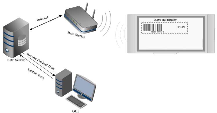
Figure 8: Electronic Price Tag System Architecture
4.2.1 Technical Specification
- Server: Server data co-works in between POS System & EPTS Client Software.
- EPTS-Client: Retailers are able to control EPTS system (Tag status, Product Information, Display Template etc.) through EPTS Client.
- Gateway: Gateway then distributes signal to Tags and also acknowledges Tag status such as Power, Error, Network and so on.
- Tag: To display product information, Tags communicate with Gateway. Display Product Info, Event, Color, Barcode, Price, Image, Promo.
4.2.2 Description
The electronic price tag system have the following features and importance;
- It uses NFC, Bluetooth to send target, relevant and timely promo to customer based on their location in store.
- Enables dynamic arrangement of content to be displayed on the tag display through the EPTS client side.
- Report back to the EPTS client side; providing battery voltage, temperature and signal strength.
- Enhance in-store experience.
4.3 Approach to the development of our case study
The approach to the development of software using DSM approach consist of some critical steps. Marjan M. et al. (2005) identified that there are five main phases of DSL development which are: Decision, Domain Analysis, Design, Implementation and Deployment, noting that DSL development is not a sequential process.
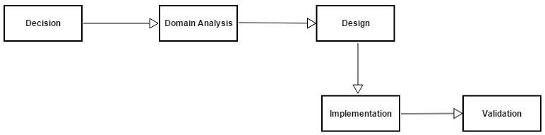
Figure 9: DSL Development Phases
As depicted in Fig 9 above, five main phases of DSL development which we have examined are as follows;
In this phase we make decision to use DSL, create a new DSL based on pattern, knowledge and experience in the domain under study. In this stage, we consider the that DSL approach to developing UI for embedded system will improve productivity and is cost effective in the long run.
In this phase, we identify and gather all relevant information about the problem domain. A representation of the domain system properties and their dependencies is the domain model. The properties are either common or variable, which is represented in the model along with the dependencies between the variable ones (Ines Čeh, 2011). The domain definition, concept and terminologies here is captured here.
Domain Analysis of Electronic Price Tag System
| Feature | Description |
| Tag | Contains tag name |
| Product Info Display | Display Product Info, Event, Color, Barcode, Price, Image, Promo. |
| Promotion | Contain promo details and product name |
| Device State | Gives battery voltage, temperature and signal strength. |
| Barcode | Contains barcode for encoding more info about the product |
In this phase, DSL components (abstract and concrete syntaxes, semantics) is defined and the best approach to implement the language is decided. In case the DSL does not exist to use the infrastructure of an existing language, a new language is developed. Here we go with developing our case study (electronic price tag system) using graphical DSL available in the tools we have chosen for evaluation. Marjan M. et. al (2005) noted that the output of formal domain analysis is a domain model consisting of
- A domain definition defining the scope of the domain,
- Domain terminology (vocabulary, ontology),
- Descriptions of domain concepts,
- Feature models describing the commonalities and variabilities of domain concepts and their interdependencies.
This phase of the DSL development describes the implementation details of the domain. It is the stage where we construct library that implement our abstract and concrete syntax and determine a modelling tool with which to implement.
According to (Steven Kelly, 2008) the steps involved in implementing a DSL which also apply to our case involves defining the modeling language for the domain, defining the domain framework and developing the code generator.
- Defining the Modeling Language for the Domain
Defining a modeling language involves three aspects; the domain concepts, the notation used to represent these in graphical models, and the rules that guide the modeling process [id=26]. In the case of electronic price tag system which is our case study, the concept of the domain stems from the UI elements (product display, promo display, barcode) and other backend services.
4.3.4.2 Defining the domain framework
The domain framework provides the interface between the generated code and the underlying platform. In some cases, no extra framework code is needed: generated code can directly call the platform components and their services are enough. Often, though, it is good to define some extra framework utility code or components to make code generation easier. Such components may already exist from earlier development efforts and products, and just need a little tweaking.
- Developing the code generator
The generator specifies how information is extracted from the models and transformed into code. The code will be linked with the framework and compile to a finished executable without any additional manual effort. The key issue in building a code generator is how the models concepts are mapped to code. The domain framework and component library can make this task easier by raising the level of abstraction on the code side.
In this phase we test the language and validate the language with the end-user.
CHAPTER FIVE
COMPARISON OF DSM TOOLS
5.1 Introduction
A lot of tools exist in the space of DSM as listed by dsmforum.org which is a body that promotes the idea of specifying domain-specific languages and generating solutions from them (Cook S., 2008). For this research work we have chosen Microsoft Visual Studio DSL Tools, GMF (Graphical Modeling Framework) and Obeo Designer limiting our work to DSM tools that offers graphical modeling.
5.2 Building EPTS with Microsoft Visual DSL Tools
For this research we made use of DSL tool of Microsoft Visual Studio 2013. Microsoft Visual Studio DSL tools support visual DSL integrated into it. Creating DSM solution in Microsoft Visual studio DSL tools involve the following processes:
- Project Setup: this involves all the steps listed below;
- Walking through the creation wizard which entails
- Selecting the project type (DSL Designer).
- Setting the name of the project,
- Choosing the template for the project, templates available are class diagrams, component models, task flows and the minimal language. For our case study, we use component model template.
- Enter a file name extension for your DSL in the appropriate wizard page. This is the extension that files containing instances of your DSL will use.
- Defining the DSL: This step involves creating domain classes and modeling relationships, shapes, connector and diagram and also, semantic validation is added.
- Code Generation: In this stage the .cs source code file is created, containing the output of the code generator.
- Debugging: In this stage the DSL solution is built by F5 where we can test the model and code generated.
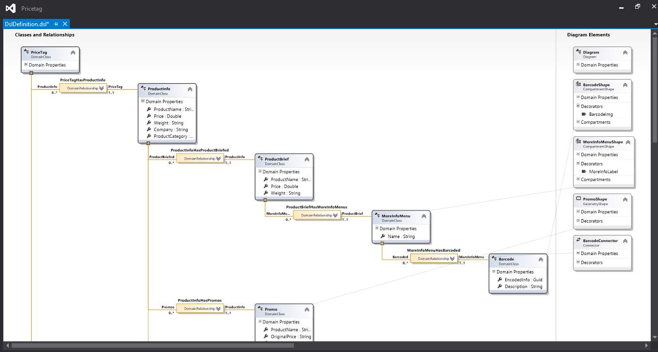
5.2.1 Modeling the Domain Concept
We will develop our case study (electronic price tag system) with MS DSL tools here and explained the concept and steps.
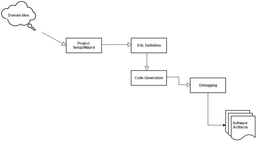
Figure 10: Steps in Creating DSM Solution in MS DSL Tools
In MS DSL tools uses an automatically laid out tree-structured notation where domain classes are represented by rounded rectangles and domain relationships are represented by square-cornered rectangles connected by lines to domain classes (Cook, 2004).
Relationships can be established between domain concepts which link them together.
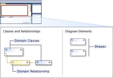
Domain classes, also called the domain concept, represents DSL elements. Domain classes are used to create the various elements in the domain, and domain relationships are the links between the elements. They are the design-time representation of the elements and links that will be instantiated by the users of the design-specific language when they create their models (Microsoft).
Two (2) types of relationship exist in MS DSL tools.
- Embedding Relationships: This represent the relationship between two model elements or domain concepts. This relationship create links between domain concepts and represent a parent-child relationship e.g. PriceTagHasProductInfo, ProductInfoHasProductBriefed, and ProductBriefeHasMoreInfoMenu.
- Reference Relationships: They also represent relationships between domain concepts but in this case a weak one. Reference relationships are mostly linked on a diagram as connectors between shapes e.g. ProductInfoReferencesBarcoded
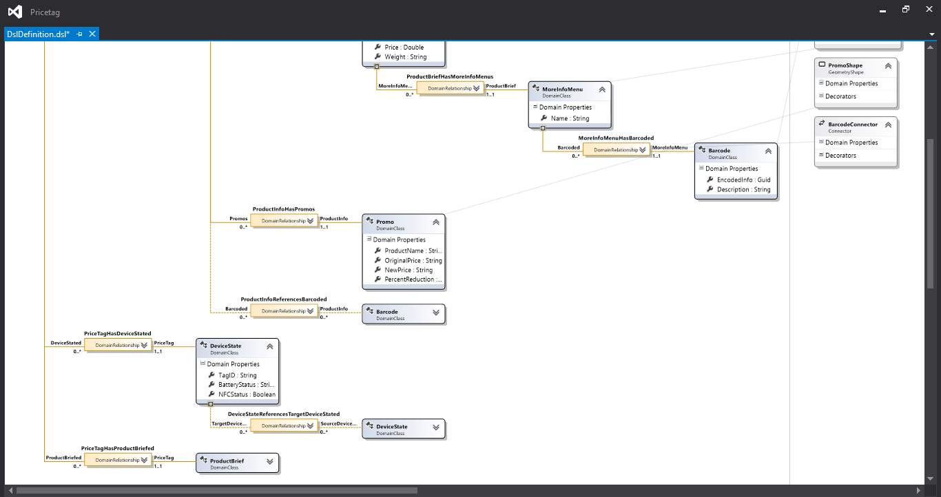
5.2.2 Graphical Notation Description
MS DSL Tools DSL designer is divided into two part; Classes and relationship and Diagram Elements, this two area represents the meta-model of our system. In the Classes and Relationship section, we have our domain classes and their relationship (embedding or reference relationship) as shown above. In the Diagram elements, we have Shapes and Connectors defined in this area. In our case study, we made use of geometric shape, compartment shape and connectors. Geometric shapes are shapes with geometric outline and allow us to set size, line thickness, fill color etc.
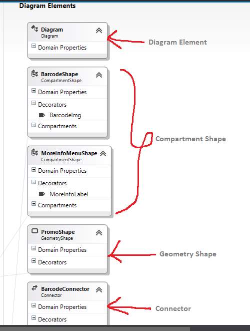
Figure 11: Diagram Description In MS DSL Tools
5.2.3 Model Mapping
This involves mapping is described below;
- PriceTag: HasDeviceState, HasProductBriefed, HasProductInfo)
- DeviceState: ReferencesTargetDeviceState
- ProductInfo: HasPromos, ReferencesBarcoded, HasProductBriefed
- ProductBrief: HasMoreInfoMenu
- MoreInfoMenu: HasBarcoded
- BarcodeShape: CompartmentMap (to Barcode)
- MoreInfoMenuShape: CompartmentMap (to MoreInfoMenu)
- PromoShape: CompartmentMap (to Promo)
- BarcodeConnector: Connector (to Barcode)
5.3 Building EPTS with Obeo Designer
Obeo Designer guarantees the set up and the deployment of industrial-strength Modeling Workbenches created with Sirius. It provides professional support and collaborative features. Modeling workbenches created with Obeo Designer are composed of a set of editors (diagrams, tables and trees) which allow the users to collaboratively create and edit models in a shared repository.
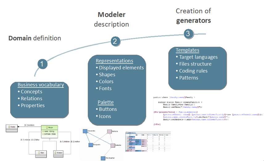
Figure 12: Steps in Using Obeo Designer
Sirius is an Eclipse project which allows you to easily create your own graphical modeling workbench by leveraging the Eclipse Modeling technologies, including EMF and GMF (Eclipse-Sirius).
Features
- Domain models are dynamically interpreted.
- It has numerous ways of representing concepts; diagrams, tables, matrices, trees.
- It make use of Viewpoint approach in which information is represented in a sufficient and necessary manner.
- Synchronization between model and generated code
- Integration to Eclipse environment: Based on EMF (ecore), GMF and Acceleo
5.3.1 Modeling the Domain

Figure 13: Ecore Model for Electronic Price Tag System
5.3.2 Graphical Notation Description
Diagrams are configured by creating a Diagram Description element (inside a Viewpoint) and its sub-elements (which describe the layers, graphical elements and tools). Like many elements inside a VSM (ViewPoint Specification Model) , Diagram Description have a mandatory Id, which should be unique and stable across revisions of the diagram specification, and an optional Label which is used for presentation purpose (i.e. it is the name visible to end-users). If no Label is specified, the Id is used for presentation.
5.3.3 Model Mapping
A mapping identifies a sub-set of the semantic model’s element that should appear in a representation and indicates how they should be represented. Each dialect offers different kinds of mappings. For example, diagrams provide container mappings, which can be used to represent semantic elements with graphical containers, where other elements (specified by other mappings) can appear. A mapping exists inside the Viewpoint Specification Model, but on a concrete representation it will produce instances (Eclipse-Sirius).
5.4 Building EPTS with GMF (Graphical Modeling Framework)
GMF is an open source Eclipse Modeling framework used for creating DSL built on EMF and GEF. It uses the EMF ecore model file as input from which it derive the templates that the graphical editor will be built from.
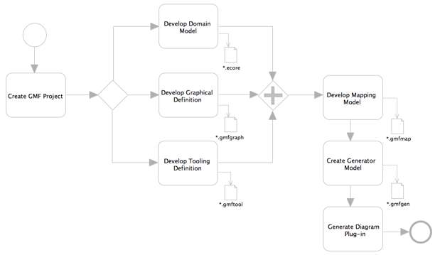
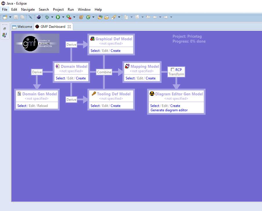
GMF uses six files to create a generated graphical editor for instances of a given metamodel like shown in the following Dashboard (Gouyette, 2010).
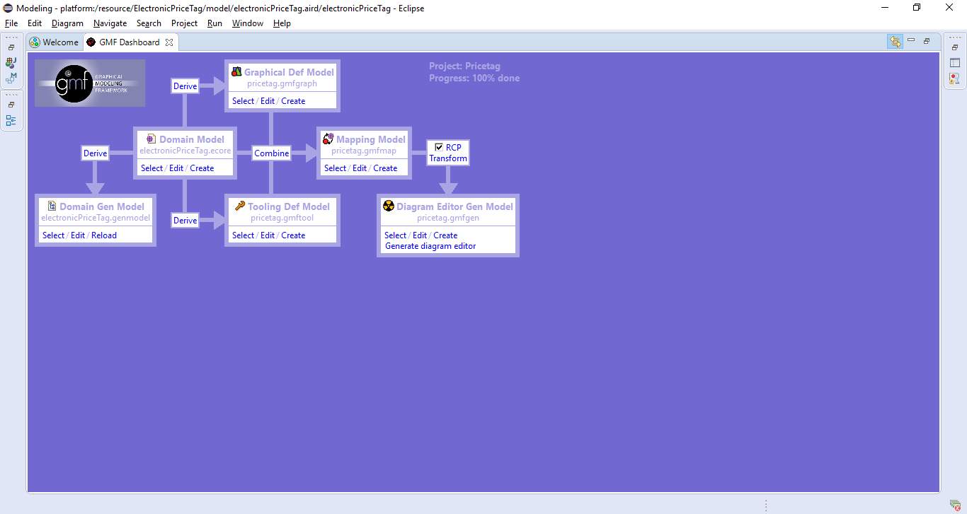
Figure 15: GMF graphical definition model
- Domain model: the metamodel we want to use to create the graphical editor. For this metamodel, you have the choice between several kinds of metamodels; Annotated Java code, Ecore model, Rose class model, UML model or XML Schema). In this tutorial we will use the ecore metamodel.
- Domain Gen Model (.genmodel): this file is used to generate the domain model code with EMF (it is the EMF file genModel)
- Graphical Def Model (.gmfgraph): this file is used to define the graphical elements for your domain model
- Tooling Def Model (.gmftool): this file is used to define the palette of tools that you can use in the graphical editor
- Mapping Model (.gmfmap): this file links the domain model, the graphical model (.gmfgraph) and the tooling model (.gmftool)
- Diagram Editor Gen Model (.gmfgen): this final file is used to generate the GMF graphical editor in addition to the EMF code generated by the .genmodel file
5.4.1 Modeling the Domain
This stage involves choosing the Ecore model defined for our case study. And deriving the EMF model from this after loading the Ecore to the project.
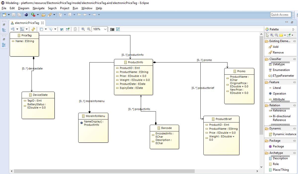
5.4.2 Graphical Notation Description
A graphical definition model is used to define the figures, nodes, links, etc. that you will display on your diagram. The model you will work with to do this is seen at the right.
5.4.3 Model Mapping
Model mapping involves importing the Ecore model of our electronic price tag system into the GMF project.
The mapping definition model will let us bind the three models we have so far: the domain, the graphical definition, and the tooling definition. This is a key model to GMF development and will be used as input to a transformation step which will produce our final model, the generation model (GMF). Here we map elements from the diagram definition (nodes and links) are mapped to the domain model and assigned tooling elements. The mapping model represents the actual diagram definition and is used to create a generator model (Gronback, 2009).
5.5 Tool Evaluation
5.5.1 Criteria for Evaluation
Ankica (2013) stated that in order to evaluate DSLs there is need for rigorous collaborative procedure and that it is necessary to;
- Define the usability criteria to evaluate DSLs by focusing on indicators that are relevant for users’ perception of quality (e.g. efficiency, effectiveness, reliability, learnability, scalability, reusability etc.);
- Integrate in an existing IDE support Quality in Use indicators; and
- Define a methodological approach to support the evolution of a DSLs based on experience and infer its impact on quality improvement during its lifecycle (e.g. traceability of design decisions, reuse of experiment results in a domain).
In the tables presented earlier in chapter 4, we noted that there were certain criteria that are needed to be tested for modern DSL tools. No research above was able to combine all criteria listed.
We also need to analyze differences and similarities between various UI designs, so we can determine their relative complexity.
In this research we put our emphasis on the following evaluation criteria for the DSL software tools, which are most relevant in our context:
- Graphical Completeness: How well can we represent the model?
- Effort: How much effort is to be invested in developing the DSL and learning the tool?
- Support/Tool assistance: Is there appropriate documentation, user communities? Does the tool support actions like “undo”, “redo”?
- Code Generation: Does it support code generation from metamodel?
- Diffuseness: How many symbols or graphic entities are required to express a meaning?
- Reusability: Can the model be reused?
- License: Is it open source or commercial?
- Maturity: Has it been used for project practical project? How many year has it been in existence?
- Model Validation
5.5.2 Tool Comparison
In this section we present the result of our evaluation based on our criteria (discussed in 5.1 above) and as a result of using these tools for developing electronic price tag system. But first we consider the language features of these tool and later in the section present the evaluation of these tools.
| Features | Tools | ||
| MS DSL Tools | Obeo Designer | GMF | |
| Metamodel | Proprietary | Ecore | Ecore |
| Artefact Format | XML | XML, XMI | XML, XMI |
| Model to Text (Transformation) | Proprietary (*.tt etc.) | ATL | ATL (QVT) |
According to the table above, the comparison of language features of the DSL tools, metamodel of MS DSL Tools is proprietary while Obeo Designer and GMF rely on EMF Ecore metamodel specification. XML format is supported in all cases for artefact format but MS DSL Tool offers a more proprietary format of XML for creating model definitions, from which the code for implementing model is generated.
Table 5: DSL Tool Comparison
| MS DSL Tools | Obeo Designer | GMF | |
| Graphical Completeness | 80% | 90% | 70% |
| Effort | Low | Medium | Medium |
| Support/Tool assistance | 80% | 60% | 90% |
| Code Generation | Yes | Yes | Yes |
| Diffuseness | 100% | 70% | 60% |
| Reusability | 40% | 100% | 100% |
| License | Commercial | EPL | EPL |
| Maturity | Yes | Yes | Yes |
| Model Validation | Yes | Yes | Yes |
5.6 Findings
According to the table above, the next section explains the criteria based on the three tools used for our development.
- Graphical Completeness: Obeo Designer offers more flexibility in this category as it is based on viewpoint representation. A viewpoint is a set of representation descriptions which provide a specific point of view on some kind of semantic model (Sirius). MS DSL Tools follow suits in terms of flexibility of how well domain model can be expressed, GUI tools for creating the model. GMF offers least.
- Effort: Although, effort is needed to learn how to use DSM tool and develop a DSM solution however, MS DSL Tools requires less effort in learning and creating DSM solution, it involves mostly dragging and linking shapes and diagrams together. It may also involve adding some codes at time if the developer choose to add semantic validation separately. Both Obeo Designer (Sirius) and GMF rely on EMF Ecore thereby requires that the domain expert create their model in Ecore before importing them into the project.
- Support/Tool assistance: GMF came with a cheat sheet thus providing user guide through using the tool for developing domain-specific solution. All the three tools discussed have online reference and user community that contain resources to help developers. All these tools support “undo”, “redo”, “save” etc.
- Code Generation: All the three tools studied in this research support code generation. MS DSL Tools produce proprietary C# code which can be compiled to a .msi file.
- Diffuseness: It takes less tools to express model in the Ecore but transforming this model concept into metamodel in both GMF and Obeo Designer require more graphics. MS DSL Tools less symbol/graphics to express a meaning since it does not rely on external model to create it metamodel.
- Reusability: For Obeo Designer-Sirius and GMF that rely on EMF Ecore modeling concept, reusing model or metamodel is the basis of these tool and so do well under these criteria
- License: Microsoft DSL Tools is installed on the Microsoft Visual Studio which is a commercial suite while GMF is licensed on EPL (Eclipse Public License) and free to use. Obeo Designer is also licensed on EPL (Eclipse Public License), available as freeware but also have options for commercial support.
- Maturity: All the three tools used in the case of this research all have been used for industrial production of complex software.
CHAPTER SIX
6.0 Related Work
In this chapter we discuss previous research work directed towards DSL, DSM tools, embedded system and usability evaluation.
(Barišić, Amaral, & Goulão, 2012) discussed performing usability evaluation of DSL based on user interface experimental validation. The authors argue that reliance on software system to perform operations has called for increase in productivity, reduced maintenance and programming expertise which DSL brings with it in its application in developing software system. They recognize that the sooner the gap between problem domain and solution domain is bridged, the better. As such there is need to evaluate the quality of the developed language so as not build inappropriate language that could increase maintenance cost and lower productivity. The authors describe that validation is one of the crucial steps in the construction of DSLs. They exponent that validation step in the development of DSL is often neglected, attributing the lack of systematic approaches to evaluation, and lack of guidelines and set of comprehensive tools for this. They also noted experimental validation based on user interface (UI) can be used to assess the impact of new DSL developed. The authors proposed a conceptual framework that involves usability concern in all phases of existing DSL’s development process which will merge usability evaluation with DSL development process.
Daniel Amyot et. al (2006) set out to evaluate the DSML supported tools by developing an editor based on a simplified version of Goal-Oriented Requirement Language (GRL) meta-model for graphical modeling language, to support their claim in evaluating these tools. GRL is used to specify and reason about business or system goals, alternative means of achieving goals, and the rationale for goals and alternatives. Five DSML tool were studied based on “relative popularity and evaluation or technical potential” and they are GME, Tau G2, RSA, XMF Mosaic, and Eclipse with GEF and EMF, evaluating how well they can be used to create the GRL graphical editor based on certain criteria. They discovered that some of these tools perform better that the other based on varying criteria. However, the authors did not test some of the tools for certain evaluation criterion – Language Evolution. The criteria the authors used to evaluate these tools and the tools evaluated are based on their perceived “relative popularity and evaluation or technical potential” – there are more popular tools.
(Tolvanen, 2014) compared how DSLs have greatly improved productivity in industries, two cases were studied because of their “relative ease of understanding from short description and that, there is already available resources/materials” for this two case; Touch screen controller (Lifinity) by Panasonic and Sports Computer by Polar, and the result indicated that DSM significantly improve productivity in the two cases than other model languages that operate more on the code level, specifying classes, inheritance etc. The author explained that in both case the same modeling tool was use – MetaEdit+ Workbench, for implementing the DSLs and generators. The author suggested that further studies should be carried out to cover other areas of the development cycle while challenging developers to further explore the “reuse” advantage DSM offers. The author compared productivity in industrial experience in two cases that use the same tool, however, it could have been more fascinating to study a case for other mature tools so as to provide a sound ground for the prove that DSM solution offer greater productivity in most cases even with different DSM tools or otherwise to show the shortcomings of this tools and to shed more light on where improvement can be made
CHAPTER SEVEN
CONCLUSION AND FUTURE WORK
7.1 Conclusion
The adoption of DSL raise the level of abstraction from raw implementation code to the actual problem domain which in turn improves code readability and makes program integration easier. It also reduces error in the testing or debugging process.
In this research we have analyzed three DSM tools for an embedded system UI by using them to develop an electronic price tag system. These tools are MS DSL Tools, Obeo Designer and GMF. We defined a set of criteria to evaluate this tools so as to lay our focus on getting to know how these tools work.
Both Obeo Designer (Sirius) and GMF rely on Ecore model concept for developing their metamodel while MS DSL Tools uses its’ proprietary modeling concept for creating its metamodel. In addition, all the three DSL tools considered here create XML artefacts but with MS DSL Tools creating more of a proprietary XML.
Embedded system software development rely on reusable components allowing developers to focus on the required variation between products to be developed. Domain-specific modeling tools and languages allow meticulous design, analysis and automatic code generation, improving system quality.
7.2 Future Work
The purpose of this study is to guide domain experts in choosing a suitable tool for developing their embedded system UI. We have shown the weakness of the selected tools and it would be important to further this research by testing them with other criteria to ensure that the actually boost productivity and increase user experience on embedded systems.
- Further work should be carried out on code analysis of the codes generated by the DSM tools so as to help DSM vendors to prevent user from generating complex codes and at the same time improve and measure performance.
- Also, further work should aim at evaluating DSM tools in all stages of DSL development supported by practical project in any exciting domains.
- It would be more fascinating to study a case for other mature tools such as MetaEdit+, MPS (MetaProgramming System) etc. so as to provide a sound ground for the prove that DSM solution offer greater productivity in most cases even with different DSM tools or otherwise to show the shortcomings of this tools and to shed more light on where improvement can be made.
References
AbasERP. (2015 , August 27). The Internet of Things and the future of ERP. Retrieved from Abas ERP: http://abas-erp.com/en/news/internet-things-and-future-erp
André W. B. Furtado, A. L. (2002). Tutorial: Applying Domain-Specific Modeling to Game. Microsoft Innovation Center at Recife/Informatics Center (CIn). Retrieved from http://www.cin.ufpe.br/~sbgames/proceedings/tutorials/SBGames06TC03_DSM.pdf
Barišić, A., Amaral, V., & Goulão, M. (2012). Usability Evaluation of Domain-Specific Languages. Quality of Information and Communications Technology (QUATIC), 2012 Eighth International Conference on the (pp. 342-347). Lisbon: IEEE.
Barn, T. C. (2013). Domain Engineering. Domain Engineering for Software Tools. Reinhartz-Berger et al. (eds.) (p. 187). Verlag Berlin Heidelberg: Springer.
Bedell, C. (n.d.). Embedded system applications present new challenges. Retrieved from Techtarget: http://searchsoftwarequality.techtarget.com/feature/Embedded-system-applications-present-new-challenges
Blake, D. (2007, May 10). Domain-Specific Languages versus Generic Modeling Languages. Retrieved from Dr. Dobb’s: www.drdobbs.com/architecture-and-design/domain-specific-languages-versus-generic/199500627
Broy, M. (2013). Domain Modeling and Domain Engineering: Key Tasks in Requirements Engineering. In M. Broy, Domain Modeling and Domain Engineering (p. 15). Berlin Heidelberg: Springer-Verlag.
Clarke, J. (2012, June). Keeping up with Embedded Development—The New User Interface. Retrieved from RTC Magazine: http://www.rtcmagazine.com/articles/view/102625
Cook S., J. G. (2008). Domain-Specific Development with Visual Studio DSL Tools. Addision-Wesley.
Cook, S. (2004). Interactive Television Applications using DSL Tools.
Daniel Amyot, H. F.-F. (2006). Evaluation of Development Tools for Domain-Specific Modeling Languages. In H. F.-F. Daniel Amyot, System Analysis and Modeling: Language Profiles. 5th International Workshop, SAM 2006, Kaiserslautern, Germany, May 31 – June 2, 2006, Revised Selected Papers (pp. 183-197). Kaiserslautern, Germany: Springer Berlin Heidelberg.
Debasish, G. (2011). DSLs in ACTION. Manning Publications.
Debasish, G. (2011). DSLs in ACTION. Manning Publications.
Eclipse. (n.d.). Graphical Modeling Project. Retrieved from Eclipse: http://www.eclipse.org/modeling/gmp/
Eclipse-Sirius. (n.d.). Specifying Viewpoints. Retrieved from Eclipse Sirius Documentation: https://www.eclipse.org/sirius/doc/specifier/general/Specifying_Viewpoints.html
Felienne Hermans, M. P. (2009). Domain-Specific Languages in Practice: A User Study on the Success Factors. Delft: Software Engineering Research Group Department of Software Technology, Delft University of Technology.
Fowler, M. (2005, June 12). Language Workbenches: The Killer-App for Domain Specific Languages? Retrieved from Martin Fowler: http://martinfowler.com/articles/languageWorkbench.html
Freudenthal, M. (2010). Using DSLs for Developing Enterprise Systems. LDTA ’10 Proceedings of the Tenth Workshop on Language Descriptions, Tools and Applications. New York, NY, USA: ACM Digital Library.
Ghosh, D. (2011). DSLs in ACTION. Manning Publications.
GMF, E. (n.d.). Graphical Modeling Framework/Tutorial/Part 1. Retrieved from Eclipse Wiki: https://wiki.eclipse.org/Graphical_Modeling_Framework/Tutorial/Part_1
Gouyette, M. (2010). GMF graphical editor tutorial: How to create a FSM graphical editor with GMF?
Gronback, R. C. (2009). Eclipse modeling project : a domain-specific language (DSL) toolkit. Addison-Wesley.
Ines Čeh, M. Č. (2011). Ontology Driven Development of Domain-Specific Languages. Computer Science and Information Systems Issue 18, 317-342.
J.-S. Lee, H. C. (2006). Domain-specific language approach to modelling UI architecture of mobile telephony systems. IEE Proceedings – Software, Volume 153, Issue 6 (pp. 231 – 240). IET.
Lawal Muideen, S. Zykov. (2016). Designing User Interface Tools for Embedded Systems: Domain-Specific Approach. 20th International Conference on Knowledge Based and Intelligent Information and Engineering Systems. York.
Microsoft. (n.d.). About Domain-Specific Languages. Retrieved from Microsoft: https://msdn.microsoft.com/en-us/library/bb126278.aspx
Sharpludus, A. W. (2006). Improving Game Development Experience through Software Factories and Domain-Specific Languages, Master Degree Dissertation, UFPE Informatics Center, Brazil. Retrieved from http://www.cin.ufpe.br/~awbf/files/AFurtadoMSc_SharpLudus.pdf
Sirius. (n.d.). Modeling Projects and Representations. Retrieved from Sirius User Manual: http://www.eclipse.org/sirius/doc/user/general/Modeling%20Project.html
Steven Kelly, J.-P. T. (2008). Enabling Full Code Generation, Wiley. In J.-P. T. Steven Kelly, Domain-Specific Modeling: (p. 448). Wiley-IEEE Computer Society Press.
Tolvanen, J.-P. (2014). Industrial Experiences on Using DSLs in Embedded Software Development. Retrieved from MetaCase: http://metacase.com
Tony Clark, B. S. (2013). Domain Engineering for Software Tools. In B. S. Tony Clar, Domain Engineering (pp. 187-209). Berlin Heidelberg: Springer-Verlag.
Cite This Work
To export a reference to this article please select a referencing stye below:
Related Services
View all


Related Content
All TagsContent relating to: "Internet"
The Internet is a worldwide network that connects computers from around the world. Anybody with an Internet connection can interact and communicate with others from across the globe.
Related Articles

DMCA / Removal Request
If you are the original writer of this dissertation and no longer wish to have your work published on the UKDiss.com website then please: