Tethered UAV Based Air Base Sense and Avoid Radar System
Info: 8789 words (35 pages) Dissertation
Published: 7th Dec 2021
Tagged: EngineeringAviation
Abstract
The future ability for commercial industry and private citizens to capitalize on the advantages of incorporating Unmanned Aerial Vehicles (UAV) into the National Airspace System (NAS) will require a safe and reliable air traffic control (ATC) system. The current NAS Air traffic control system requires manned control towers and “See and Avoid” capabilities to navigate under current regulations. The Federal Aviation Administration (FAA) is developing an UAV traffic management (UTM) system to support beyond line of sight UAV operation below 400 ft,. The unaffordability of developing a manned ATC system for small UAV’s is leading to the development of an UTM system that requires all operators to register their UAV, publish flight plans, and self-regulate the airspace. UTM’s success is based on all operators and aircraft participating, but airspace safety incidents from non-participating aircraft provides a foundation to investigate an alternative UTM solution. Evidence suggests employing a cost effective air based sense and avoid radar system over urban environments and high-density population zones areas can reliably identify participating aircraft, non-participating aircraft, and non-cooperative objects. The system will consist of a ground control station, tethered UAV, and Radar system. Utilizing the tethered UAV with the integrated radar payload will provide continuous operational data, prevent ground clutter interference and manage the transition from UTM to controlled airspace for safe operations. The tether will transmit ground power, command and control data to operate the UAV at a height of 400 ft., and transmit real-time radar tracks of all objects detected. Implementation of a powered to tethered UAV system with a radar payload will meet the “See and Avoid” requirements and allow beyond visual line of sight operation for the future.
Keywords: Tethered UAV, RADAR, UTM
Introduction
The growth of commercial and public traffic sectors has demonstrated a need for orderly and safe traffic management systems. The evolution of the automobile developed a need for rules of the road, roadways, and traffic signals. The advancement in the commercial and public aviation industry created a similar need for rules of the air, establishing airways, and the development of an air traffic control (ATC) system. The origins of ATC began with the Air Commerce Act of 1926, that provided the ability to enforce air traffic rules, require pilot licenses, and certification of aircraft, and continued with the creation of Federal aviation Act of 1958 that created the Federal Aviation Agency (FAA) (FAA, 2017). Over the last decade, the commercial, public, and defense industries have seen a tremendous growth in the development of unmanned aircraft systems (UAS) that are capable of being operated well beyond line of sight.
UAVs are available in fixed wing and mutli-rotor combinations that can accommodate a number of sensors and payloads at affordable costs. UAV operations, similar to manned aircraft, require the proper licensing, training, safety protocols, and must operate within visual line of sight (VLOS) for operation in the National Airspace System (NAS), but are difficult to enforce. FAA requirements under the small unmanned aircraft rule, part 107, require operations to be performed within VLOS of the remote pilot in command and the person manipulating the flight controls (FAA, 2016). The commercial and public sectors have demonstrated benefits for beyond visual line of sight (BVLOS) operation in low-altitude airspace at heights of 400 ft. above ground level and below to conduct deliveries, agriculture, mapping, photography, search and rescue, and disaster relief to highlight a few (Maryland Department of Commerce, 2015). The FAA estimates the small UAV hobby fleet will reach 3.55 million by 2021 and the commercial fleet will reach 0.422 million (FAA, 2017).
President Donald J. Trump directed U.S. Secretary of Transportation to develop a UAV Integration Pilot Program to safely test and validate advanced operations for drones in partnerships with state and local governments, that will result in the acceleration of safe integration of UAV into the NAS and realize the benefits of unmanned technology on our economy (U.S. Department of Transportation, 2017). Due to the large interest from Industry, private citizens, State and Local authorities, the FAA is developing a low altitude ATC system to safely accommodate all manned and unmanned aircraft, to include allowing BVLOS operations.
The FAA will need to develop the rules for the NAS for all operators, even those that are not trained aviators. UAV operations will only provide a safe NAS if all UAV operators participate in a low altitude ATC system. The expected growth in the UAV industry will lead to unsafe air transportation without additional technology. Developing a low altitude Radar that can quickly be deployed for localized ATC will be required.
Background
The FAA and National Aeronautics and Space Administration (NASA), with support from industry are developing an Unmanned Aircraft Systems Traffic Management (UTM) system that creates a regulated, self-identification, air traffic management system that supports real-time or near real-time airspace status between the FAA and operators in unregulated airspace (FAA, 2017). The UTM architecture is shown in Figure 1, which presents a strategy for all cooperative aircraft to function safely in the NAS.
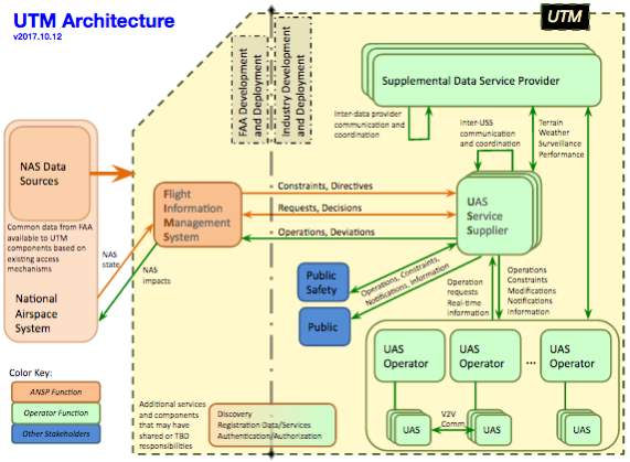
Figure 1. NASA UTM architecture for low altitude airpsapce operations and control (Aweiss, Owens, Rios, Homola, & Mohlanbrink, 2018)
The UTM architecture is based on cooperative operators and has no ability to detect or see uncooperative aircraft or non-cooperative objects, such as towers or birds. The UTM system requires the UAV operator to file flight plans with a UAS Service Supplier (USS). The USS will validate and coordinate flight plans with other USS’s, the FAA, and supplemental data providers in real-time. If the USS receives no flight plan conflicts, it provides authority for the UAV operator to begin operations. The UAV operator has to provide real-time flight data to the USS, so it can share positon and intentions with other operators and the FAA.
The integration of the UTM system, as an ATC measure, provides awareness to all other participating aircraft. A future NAS with millions of cooperative and uncooperative UAV operating over urban environments could have a potential to cause catastrophic or fatal injuries due to mid-air collisions. Cooperative operators will have no way to see and avoid an uncooperative aircraft when flying beyond line of sight.
A study conducted by Virginia Tech, revealed a wide variation of injuries could be sustained from a small UAV to human impact, with data ranging from 10 percent to 70 percent of potentially severe neck and head injuries for drones weighing between 2.6 Lbs. and 24.2 Lbs. (Lillian, 2017). The risk associated with uncooperative aircraft causing human or property damage is too significant and requires additional technologies to be developed, for heavily congested airspace or urban environments.
Case Study
A case study of a black hawk helicopter damaged by a small UAV provides an example of how UTM, as the ATC alone, will not safely manage manned and unmanned aircraft in the NAS.
On September 21, 2017 a hobbyist, flying a small UAS under federal regulation Title 14 Part 101 at a height of 300ft, in normally allotted Class G airspace, collided with a Black Hawk helicopter that was flying under a temporary flight restriction. The UAS operator was found to be at fault for intentionally operating beyond visual line of sight and not checking for temporary flight restrictions, even though he was operating below 400 ft. (UAS Vision, 2017).
Analyzing this scenario, if an operational UTM system was in operation, the outcome may still have not been avoidable. If the operator was participating in the UTM system, the USS would not have allowed the operator to file a flight plan and provided warning that the airspace was under a temporary flight restriction. The operator would have not flown, preventing the mid-air collision. The operator could still chose to fly, but the flight data would be captured by the FAA and appropriate action could be taken by authorities. If the operator was unaware of FAA regulations or decided not to participate in the UTM system, a mid-air collision would occur, producing the same outcome. The observations from this case study, the commercial and civil growth of UAV operations, and the potential for severe human injuries led to a research question focused on addressing a cost effective “see and detect” technology for small UAV integration into the NAS:
RQ1: Is it possible to effectively use a tethered UAV integrated with a radar sensor to provide a 360 degree aerial view of cooperative and uncooperative small UAV below 400 ft.
RQ2: Is it possible to integrate the radar tracks into the UTM system, alerting the participating aircraft of the non-participating aircraft and non-participating objects location.
The need for an additional “see and detect” technology will be required to safely integrate UAVs into the NAS. The research question will investigate the available technology and the approach of using a tethered UAV with a Radar sensor to detect at a cylinder that is 10 km diameter and up to 400 ft. The research will investigate the design requirements, technology available, and the effectiveness of meeting these mission requirements.
The remainder of this research paper is structured as follows. A literature review will cover the research conducted into the theory of utilization of small tethered UAV and miniature radar system capabilities. Then a general overview of the system followed by the decomposition of design decisions for the three major subsections that consist of the ground station, the UAV, and the radar system. The next section will cover the limitations of each design. The command and control structure will be analyzed and it concludes with a discussion of results, the effectiveness of the solution, as well as areas of future research.
Literature Review
The first UAV was developed over a 100 years ago with a primary focus on military missions, but in 2009 the introduction of cost effective hobby grade small UAV at the Consumer Electronic Show led to the mass development for commercial and consumer UAV systems that were reliable and easy to fly systems (CraigI, 2015). The advancements in UAV system technology, since the market establishment of the market in 2009, has included autonomous flight control, auto take and landing, altitude hovering, object avoidance and a large number of payloads, from 4K motion video to commercial agriculture fertilizer systems (Joshi, 2017). The commercial and hobbyist UAV market is flooded with Group 1 lithium ion battery powered UAV’s that have limited flight time to 15 to 30 minutes, depending on the payload. Expansion of the UAV market to conduct extended flight times for commercial and military operations has created a market for low cost tethered UAV systems.
Tethered UAV’s provide long endurance high definition video for film and live events that provide a different view to the audience (Brown, 2018). Military operations have invested in tethered UAV’s to perform intelligence, surveillance, and reconnaissance (ISR), security, and overhead inspection that can operate up to 800 feet supporting payloads requirements of up to for 15 pounds and 1 kilowatt of power (Carey, 2016). Different approaches have analyzed methods of powering long endurance hovering UAVs by considering power over tethering and laser power beaming as methods of supplying constant power (Zikou, Papachristos, & Tzes, 2015; Achtelick, Stumpf, Gurdan, & Doth, 2011). Approaches to the power management system have considered both direct current and alternating current methods for applying power up the tether to limit the size and weight of the tether and power regulation.
Multiple models of the kinematics and dynamic flight control of a tethered UAV have been developed under conditions of a taught and dynamic tethers using Lagrangian mechanics to evaluate a stable altitude flight control (Lee, 2015; Nicotra, Naldi, & Garone, 2017). Several authors have researched methods for the winch, inside the ground control station, to control the tautness of the tether to maintain altitude and increase flight stability (Sandino, Bejar, Kondak, & Ollero, 2104; Zikou, Papachristos, & Tzes, 2015; Muttin, 2011). Utilizing a taught cable design has demonstrated advantages to controlling altitude and stabilization.
The radio aim detecting and ranging (Radar) sensor uses electromagnetic pulses that are reflected off from an aircraft and are unaffected by light, weather or clouds, to detect position and speed of the aircraft (Wolff, 2009). Miniaturized Doppler radar systems have been developed to provide an air based sense and avoid system for manned and large unmanned aircraft to meet the FAA requirements for a sense-and-avoid system that can detect aircraft and when required maneuver the UAV to maintain the required air space separation (Duffy, 2014). Utilizing an Air based radar system will reduce ground clutter that occurs from typical ground based radar systems, by detecting the airspace from above.
Operational Domain
The demand growth for UAV use in the NAS will require additional radar detection capabilities in the dense urban environments and areas of congested air traffic. According to Joshi, the commercial and hobbyists will utilize UAV’s for the operations listed in Table 1 (2017).
Table 1
Operations Conducted By Future UAV Operator Groups
| Operations | Hobbyists | Commercial | Government/Military |
| Aerial photography/film | X | X | |
| First person control | X | ||
| Shipping and Delivery | X | X | X |
| Search and Rescue | X | X | X |
| Disaster relief | X | X | X |
| Infrastructure inspections | X | X | |
| Precision agriculture | X | X | |
| Law Enforcement | X | ||
| Storm tracking | X | X | |
| Traffic monitoring | X | X | X |
| Geographic mapping | X | X | X |
(Joshi, 2017)
To maintain operational awareness and a safe NAS, the tether UAV system would be operated around airports, helipads or any areas with high manned aircraft traffic. The systems will also be utilized in dense urban environments, areas that have a high likelihood of uncooperative operators, and areas that limit ground based sense and avoid radar systems from detecting small UAV’s, due to terrain and buildings that can block or washout the radar signal.
System Users
The system will be utilized by state and local authorities or commercial USS services that provide authority over the airspace at 400 ft and below. Airport authorities would utilize this technology to protect approach routes where manned aircraft is crossing through the 400ft and ground level zone. Local authorities will want to provide protection to their citizens at large events, over crowds, or over schools. The system will be portable to support first responders for search and rescue or humanitarian aid/disaster relief operations to provide airspace traffic control where no UTM service or utilities are available.
Design Overview
The tethered UAV radar system will consist of a ground control system that provides the ability to control the deployment and operation of the UAV to perform radar detection of Small UAV’s in congested airspace. The ground station will supply constant power through shore power or by backup generator to the UAV allowing it to stay airborne unless extreme environmental conditions or needed maintenance ceases operations. The UAV will transmit the radar tracks through the tether to the ground control station where it will be transferred into the UTM architecture, allowing all cooperative UAV’s and manned aircraft to see the uncooperative aircraft. The ground control station is fitted with a transceiver to launch the UAV to any prescribed altitude of 400 ft or below. Environmental data will be transmitted through the UTM system allowing the system to automatically retract the UAV, if the conditions reach a set thresholds equal to the UAV’s performance capabilities.
Figure 2 provides a high level architectural design diagram of the entire system. The UAV will use open source and commercially available flight controls that have a demonstrated capability to hover at altitude, using GPS, accelerometers, and gyroscopes. The onboard computer processor will analyze the radar sensor data, capture the position data and transfer it at a rate of 1 Hz or greater into the UTM system. The UAV will include a battery backup system that will have enough power to allow the UAV to land safely if it detects power is lost from the tether. The ground control station will include an electric winch to control the tension on the cable that has the ability to retract the UAV at full thrust.
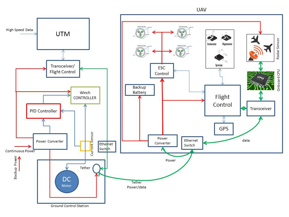
Figure 2. Proposed tethered UAV with integrated Radar sensor architectural design diagram
Design Decisions
Ground Station
The ground station will be the base for operations that will store, deploy, retract and operate the tethered UAV and radar sensor. The ground station will be integrated with a diagnostic feed to provide the operator feedback on the performance of the system during operation. The ground station is required to be portable, capable of being deployed quickly and capable of withstanding the environmental elements. The system needs to be man portable and fit through a standard 36 inch door so that it could be deployed from a roof top in urban environments. The ground station will be required to provide consistent power to the UAV through the tether, requiring an external power source of 240 V. The rest of the ground control station will consist of a winch system with tether cord, winch control system and transceiver system integrated with UTM.
The Ground station requires access to high speed data communications that can provide real-time radar tracks over Internet Protocol communication standards, required to feed data into the UTM architecture from the radar sensor. The ground station will receive local weather conditions and have external data inputs that can autonomously control the operating status of the tethered UAV system.
Winch System and Control
The winch system will maintain a constant tautness on the cable to help stabilize the UAV in flight and control the tether cable during ascents and descents of the UAV. A DC motor will be used to spool the cable drum with a current sensor in line to determine the amount of power being consumed. Morales-Perryman & Lee discovered by using a Porpotional-integral-derivative (PID) controller to read the current sensor data, the PID controller can modulate the voltage to the DC motor to control the taughtness of the cable (2013). Ohms law defines the relationship between current, I, in amps, the applied voltage, V, and the resistseance, R, in ohms.
I=VR
If R is consistent for a given electric motor design, then the torque will be directly porpotional to the voltage being supplied. The constant feedback loop will allow for smooth operation as the torque on the drum changes relative to the amount of cable spooled on the drum, the new weight of the tether and UAV and the enviromental conditons affecting the UAVflight perfromance.
The tether design requires a lightweight, robust cable that can support the loading encountered by the UAV flight dynamics, can pass power and data without any significant loss, and meet safe handling regulations. Controlling weight of the tether cable design is important to provide maximum payload lifting capacity and UAV flight stability. The tether is designed around the power requirements, which will be discussed in the power system. The tether cable will include two, LYNX-OEM-3P, Ethernet over power cable switches, removing the need for a separate data cable inside the tether cable (Atlanta Instrumentation and Measurement, LLC, 2015). Figure 3 shows the configuration of the power supply to vehicle utilizing the Ethernet over power switches with no requirement for an additional data cable. The switches are only 50 grams each, which provides additional payload capabilities for the UAV.
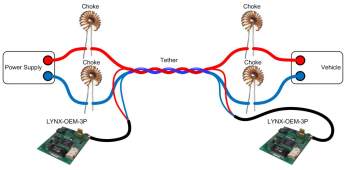
Figure 3. Ethernet over power switch diagram
(Atlanta Instrumentation and Measurement, LLC, 2015)
Power System
To provide unlimited flight time of the UAV, power is required to pass along the tether to the UAV. The UAV’s brushless electric motors operate on 24V or 48V DC power. For the electric motors to provide sufficient thrust at 24V DC voltages, the system will demand higher amps, that require larger gauge tether conductor wires to prevent excessive voltage drop and overheating of the cable at 400 ft. To solve the power problem, the UAV will utilize a known power (P) required to stay aloft, by increasing the voltage (V) the current (I) will be reduced by the following equation:
P=VI
The system requires the lightest and smallest cross sectional area tether to prevent increased loading from the wind, acting like a sail. The UAV minimum power required is defined by the amount of thrust needed for the system to hover. The power is defined by the overall system weight. The current can be reduced, requiring a smaller gauge wire, if the voltage is increased. Kiribayashi, Ashizawa, & Nagatani conducted a study that modeled and tested different optimal gauge tether wires to understand how the ressisance affected the power supply at the uav when fully extended (2015). They determined that a twisted pair of 20 American Wire Gauge (AWG) wires, with a denisty of 27.5 g/m, provided an optimal solution at 32 V and a height of 40m (Kiribayashi, Ashizawa, & Nagatani, 2015). To reach 400 ft. the weight of the cable would be approximatly 3.5 Kg utilizing a 32 V power system. According to a study by Kiribayashi, Yakushigawa, & Nagatani, they discovered increasing the voltage to 600 V DC would reduce the tether cable gauge and allow them to maintian 1200 Watts of power in the UAV (2017).
To maintain an acceptable thrust to weight ratio for flight stability and dynamics, The total thrust, T, should be twice the overall system weight, W (Selvaganapathy & Ilangumaran, 2017).
T=2W
The weight allotments for each of the subsystems are defined in the Table 2 and are used to define W.
Table 2
Weight Allotments for the UAV Tether System
| Sub System | Weight (Kg) |
| UAV and Avionics | 11 |
| Radar Sensor | 18 |
| Power Converter | 1 |
| Camera | .5 |
| Tether (fully extended) | 4.5 |
| Total | 35 |
The total thrust, Ttotal, is calculated at 70 Kg of thrust required for all electric motors. The total thurst per engine, Tengine, is calculated by
Tengine =
TtotalN
where, N, is the total number of engines on the UAV. Using a quad rotor design, Tengine, would require 17.5 Kg of thrust for each engine, that would require custom designed elcetric motors and propellers to support the system design. Using an octorotor design requires Tengine, to be 8.75 Kg thrust for each electric motor.
Analyzing commercially available motors, the KDE10218XF-105 fitted with 70 cm KDE-CF305-HP Hex rotor blade can geneate 9.8 Kg of thrust at 50 percent throttle, for Ttotal of 78.5 Kg (KDE Direct, 2018). This combination will require approximatly 600 Watts to hover and draw approximatly 20 Amps per motor.
The tether will supply 600 V at approximately 4 amps, where it will be regulated to 48 V and 25 Amps to supply for the electric motors and radar power requirments (Russell & Mezin, 2016). According to Blattenberger, a 20 AWG wire capable of hadling 7.5 Amps, detailing a total teather weight of 3.5 Kg, fits in the alloted weight budget of 4.5 Kg and meets the desing requirments (2018).
Transceiver
The transceiver will allow for the transmission and receiving of data across the tether. The transceiver is required to transfer data at a minimum of 40 Mb/s to process the Doppler radar tracts (Echodyne Corp , 2017). The receiver will send the radar tracts across the local area network (LAN) to the IP based UTM network. The transceiver will have the capability to process full motion video from the UAVs onboard camera and transport over LAN to operators or optional recording devices at the ground control station.
UAV
The UAV will consist of the platform, integrated flight control, onboard processing, communication link, backup power source, and power conversion to maintain operation for extended periods. The UAV will be required to sustain flight at a height of 400ft. above ground level carrying the Radar payload, the backup power source, the power conversion, and the weight of the tether system. The system will utilize an integrated GPS sensor and IMU to control altitude and attitude stability during operations. The UAV on board processor will conduct sensor fusion of the GPS, IMU, and external inputs. The UAV will require both onboard battery backup power that is charged from the tether along with electrical control components to utilize the power being transferred from the tether.
UAV Design
The octo-rotor UAV design must consider the load and flight agility that will be required at 400 ft. above ground level. The UAV, radar payload, and tether will weigh 35Kg, with engines that have a capability of over 19.6 Kg of thrust at full throttle. The arm design must be capable of supporting 19.6 Kg of load and support the rotor blades that have a 77.5 cm (RL) tip to tip length. The octo-rotor design will consist of equally spaced arms every 45 degrees around the center body of the UAV. The arm length (AL) is calculated using trigonometry functions.
AL=12*RLSin 22.5=38.75Sin 22.5=
101.2 cm
The UAV will have a minimum arm length of 101.2 mm to prevent the blades from contacting during operation and require a 279.9 cm take-off and landing zone. Figure 4 provides the layout of the critical dimensions required to make the UAV design feasible for Radar payload mission.
The center hub of the UAV will house the flight controller, the processor, sensors, GPS antenna, power convertor, spare battery and radar payload. Using a radar design similar to the SHARPEYE – SXV, would require a set of retractable landing gear that provides a minimum of 58.5 cm X 26.2 cm of clearance under the UAV for takeoff and landing (Kelvin Hughes, 2014). Retracting the landing gear upon take-off prevents the landing gear from obscuring the Radar signals. The sketch in figure 4, highlights the design configuration. Figure 5 describes the design requirements to integrate the radar payload.
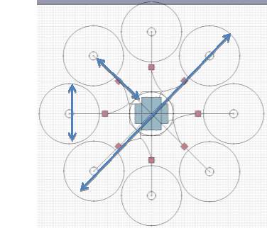
Figure 4. Octocopter UAV critical design requirements for 35Kg system
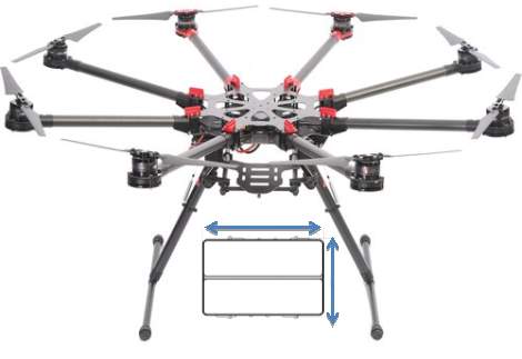
Figure 5. Octocopter Radar payload clearance requirements
Dronenerds. (Photographer). (2018) [digital image]. Retrieved from https://www.dronenerds.com/products/drones/enterprise-drones/spreadingwings/s1000s/s1000-a2.html
UAV Flight Control
The UAV will be integrated with a small stereo vision camera that can process images as a backup classifiyer to the Radar sensors. The camera will also be used to capture images of passing uncooperative aircraft or objects that could be used by enforcement officials to prosecute or train individuals on the importance of UAV safety.
The blades will be fitted on the, KDE10218XF-105, electric motors that can producte the required torque and thrust to support the UAV (KDE Direct, 2018). The UAV will use industry standard JST connectors to connect the GPS, IMU and retractable landing gear to the flight controller. The GPS antenna will mount on a mast, above the UAV, using U.FL RF connectors. The power connections will use industry standard XT60 connector from the power converter to the ESC controller and backup battery. A gigabit Ethernet connection using a cat6 cable will transfer data from the Radar Sensor to the onboard processor passing thru the tether to feed high speed track data to UTM.
The UAV, avionics, and camera will need to weigh less than 12.5 kg and incorporate a mount for the radar and connection for the tether. The system should be aerodynamically stable with eight rotors and 2:1 thrust to weight ratio. The system will be made of high strength, lightweight components like carbon fiber.
Radar System
The Radar system will consist of the Radar sensor, onboard processor, and self-diagnostic reporting. The Radar sensor is required to detect, track and identify participating aircraft, non-participating aircraft, and non-cooperative objects. UAV’s are capable of flying slow and their size can easily be mistaken for a bird, requiring for the Radar to classify the object.
Micro-Doppler radars, using the X-band frequency, can detect and classify rotating components along with the full body motion of the object, to determine the difference between UAVs and birds or fixed objects (Berroth, et al., 2014). The rotating array radar will operate in the 9.22 – 9.38 GHz range (Kelvin Hughes, 2014). Berroth et al., determined that rotating components of an object are detected by the radar as separate scatters, creating a distinctive Doppler frequency shift, that could be used to classify the UAV configuration (2014). The classifier would only have to detect a rotating blade to produce a track that could be used to notify the UTM system, as the UTM system doesn’t need to know the UAV specifics, just its location in the airspace. Figure 6 is a proposed model of the micro-Doppler Radar detecting the rotating blades of a UAV.
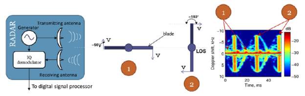
Figure 6. Radar system capturing micro-doppler frequency shift of rotating blade. (Berroth, et al., 2014)
The Radar software would remove the background scatter noise and align the Doppler frequency shift with the full body motion to extract the rotating features, which could then classify the UAV (Berroth, et al., 2014).
A continuous wave step radar, operating at 17 GHz, has also been used in short range test experiments to track the back scatter and determined a Doppler frequency shift created from UAV (Pieraccini & Miccinesi, 2017). The continuous wave step radar can systematically vary the transmitted frequency, instead of measuring the instantaneous rate-of-change, by measuring the time delay of the returned frequency reflected off the object in the airspace (Federation of American Scientists , 1998). The different radar frequencies provide options for different terrain and environments, where reflections and noise could be tuned out of the radars data.
The radars can detect approximately 5km and have a 120 degree field of view, with increased accuracy at closer distances (Kelvin Hughes, 2014). The Radar sensor would be able to cover the 400ft. and below requirement and provide warning to the cooperative aircraft of an object within a 10km diameter ring of operation. Multiple types of Radar sensor options and frequencies could package and meet the power requirements available in the tethered UAV.
Design Limitations
The system does have design limitations that could be possible to overcome with further technology advancements. The entire system will have operational limits due to environmental conditions. The system will be grounded during high winds, lightning storms, and extreme snow/icing events. Hobbyists and commercial UAVs would be limited or unable to perform in similar weather events, allowing these design limitations to be acceptable given the benefits to ATC.
Ground Control Station
The ground control station will require constant power that may not be available in the operational location and could rely on a generator to supply the power. If running off the generator, an individual would be required to monitor the fuel and performance of the generator every couple of hours. Alternative power studies could be performed to investigate using 240 V AC in the tether, utilizing a AC to DC convertor in the UAV. The design would need to investigate weight and thermal management concerns.
UAV
The overall weight and size of the system could limit the UAV from being mobile by a single person and provides more restrictions on the take-off and landing zone requirements. The UAV will also be classified as a Group 3, which is a UAV that weighs more than 55 lbs, requiring a Section 333 exemption from the FAA. (Federal Aviation Administration, 2017) (Abdullah, 2017).
The UAV will require thermal management of the heat generated by the DC to DC converter and the Radar. In extremely hot environments with little airflow around the system, the performance could be degraded. A heavier tether wire capable of supporting 48 V, which adds weight to the system, could be utilized to reduce from 600V to 48V in the tether, removing the need for the DC to DC converter and thermal stress on the system.
Radar System
Stabilized flight and attitude of the UAV is needed to maintain orientation of Radar sensor to collect the radar tracks. If the UAV attitude or hover altitude is unstable, the radar beam may not cover the ground level to 400 ft. of elevation, missing objects in the airspace. Integrating a gimbal to maintain stabilized orientation of the radar would provide a constant airspace picture, but the additional mass is currently not in the design budget. Converting the radar track position data using inverse kinematics to the UAV global Cartesian axes would provide a consistent 3D positioning of the tracked object as well, but would require additional algorithm and software development. The radar design limitations could be resolved with these solutions allowing for an increased level of position accuracy, tolerating closer air operations between systems.
Logic Design
UAV Control
The winch system will maintain a constant load on the tether as part of the UAV control theory, utilizing a constant force in the tether to maintain altitude and flight stability. In a study conducted by Nicotra, Naldi, and Garone, the UAV maintains hover control using a taut cable with an embedded loop control strategy based on a reference governor that can account for errors and maintain linear control (2017). Figure 7 highlights the embedded control logic for the UAV.
The ground control station will control the tautness on the tether, by calculating the current draw on the electric winch, allowing the UAV to optimize it’s flight control in heavy winds. The winch will increase torque on the motor not allowing more than 400 ft to be extended, working in combination with the UAV flight control logic.
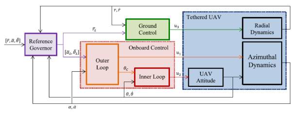
Figure 7 UAV control logic for taut tether cable (Nicotra, Naldi, & Garone, 2017)
Radar Sensor and Track
Figure. State diagram of UTM operating with intruders or unknown objects being introduced to the airspace (Smith, et al., 2017)
The radar sensor will transmit the track data to UTM over an IP address using application programming interface (API) that is required to be a compliant with the USS. The APIs provide the data format and transfer protocols to exchange data over the UTM servers (NASA , 2017). The UTM state diagram represented in Figure 8 shows how UTM will accept data as an intruder. The intruder data will be captured by the radar feed detecting the uncooperative aircraft and publishing the Radar tracks to UTM. UTM will publish the tracks to all aircraft in the area as a warning and allowing operators to redirect or land. UTM will disregard any radar tracks that correlate to participating aircraft.
The ground control station will transmit the radar tracks in the API format found in the open source USSREQ-API, allowing the USS suppliers to include the tracks in their shared airspace model (NASA , 2017). The USSREQ-API would use the code and data format found in Appendix A. Operators would receive the warning data, allowing the selection of manually or autonomous control of the UAV to take evasive action to avoid a collision.
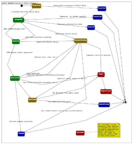
Figure 8. UTM and radar track state logic for identifying an intruder (NASA , 2017)
Conclusion
The need for a low altitude Radar system that can detect uncooperative UAV and objects could provide a safe NAS for all operators of manned and unmanned Aircraft. The study revealed that a small UAV integrated with a micro-Doppler Radar system could be used to effectively to detect uncooperative aircraft using frequency shift of the blades to determine the object. The flight time and performance of the UAV would be limited, if operated off from battery power not making the system feasible. Utilizing a tether to supply constant power to the UAV and providing a mechanism for high speed radar track transfer creates a viable system. The size and power requirements of the system would make it portable, allowing operations to move to high air traffic locations. The solution developed in this research paper would provide an effective and efficient solution to RQ1.
The FAA is developing a UTM system that will coordinate and execute air traffic control at low altitudes. The UTM system provides APIs to receive Radar tracks for uncooperative aircraft and considers them intruders in the system. The tethered UAV onboard processor will provide the radar tracks of all aircraft detected and pass it over the tether to the UTM IP based servers. UTM APIs define the required protocol to accept the Radar tracks and publish them to all of the USS operations. This UAV tethered Radar system will answer RQ2 to effectively provide air space awareness to all manned and unmanned aircraft operators.
Future research would require Radar performance and tuning analysis based on the ground clutter and the background environment. An automated Radar tuning algorithm could be developed to provide the optimal settings on its initial take off, preventing the need for a qualified Radar operator during setup. Advanced tether materials could be examined to produce a lightweight tether design that would provide less drag on the UAV operating at full height.
References
Abdullah, Q. A. (2017). Geospatial applications of unmanned aerial systems (UAS). Retrieved from Pennsylvania State University: https://www.e-education.psu.edu/geog892/node/5
Achtelick, M., Stumpf, J., Gurdan, D., & Doth, K.-M. (2011). Design of a flexible high performance quadcopter platfrom braking the MAV endurance record with laser power beaming. Intelligent Robots and Systems (pp. 5166-5172). San Francisco: IEEE. doi:10.1109/IROS.2011.6094731
Atlanta Instrumentation and Measurement, LLC. (2015). Digital LYNX. Retrieved from Atlanta Instrumentation and Measurement, LLC: http://aimatlanta.com/wp-content/uploads/2015/04/LYNX-Connection-Diagram.png
Aweiss, A., Owens, B., Rios, J., Homola, J., & Mohlanbrink, C. (2018). Unmanned aircraft systems (UAS) traffic management (UTM) national campaign II. AIAA SciTech Forum (pp. 1-16). Kissimmee: National Aeronautics and Space Administartion. doi:10.2514/6.2018-1727
Berroth, M., Jacob, A. F., Schmidt, L.-P., Molchanov, P., Harmanny, R. I., de Wit, J. J., . . . Astola, J. (2014). Classification of small UAVs and birds by micro-doppler signatures. International Journal of Microwave and Wireless Technologies, 6(3-4), 435-444.
Blattenberger, K. (2018). Copper wire properties & gauge conversions. Retrieved from RF Cafe: http://www.rfcafe.com/references/electrical/wire-cu.htm
Brown, M. (2018, February 18). From tethered drone to cars that expand on a touch: daytona 500 tech for fOX sports. Retrieved from Forbes Web Site: https://www.forbes.com/sites/maurybrown/2018/02/18/from-tethered-drone-to-cars-that-expand-on-a-touch-daytona-500-tech-for-fox-sports/#7f50e7403cce
Carey, B. (2016, July 25). U.S. Army evaluates one of a new breed of tethered drones. Retrieved from Aviation International News Web Site: https://www.ainonline.com/aviation-news/defense/2016-07-25/us-army-evaluates-one-new-breed-tethered-drones
CraigI. (2015, August 21). The drone report 2016. Retrieved from Drone Flyers web site: https://www.droneflyers.com/the-drone-report-2016/
Dronenerds. (2018). Spreading wings S1000+ octocopter with A2 flight controller. Retrieved from Dronenerds Web Site: https://www.dronenerds.com/products/drones/enterprise-drones/spreadingwings/s1000s/s1000-a2.html
Duffy, S. M. (2014, October). Airborne sense and avoid radar panel. Retrieved from Massachusetts Institute of Technology Lincoln Laboratory: https://www.ll.mit.edu/publications/technotes/TechNote_ABSAAPanel.pdf
Echodyne Corp . (2017, June 26). MESA-DAA. Retrieved from Echodyne Corp Web Site: https://echodyne.com/wp-content/uploads/2017/08/MESA-DAA_Product_Sheet.pdf
FAA. (2017, August 15). FAA aerospace forecasts. Retrieved from Federal Aviation Administaration: https://www.faa.gov/data_research/aviation/aerospace_forecasts/media/Unmanned_Aircraft_Systems.pdf
FAA. (2017, May 16). Unmanned aircraft system traffic management (UTM). Retrieved from Federal Aviation Administration Web Site: https://www.faa.gov/uas/research/utm/
Federal Aviation Administartion. (2017, May 16). Unmanned aircraft system trafffic management (UTM). Retrieved from Federal Aviation Administration: https://www.faa.gov/uas/research/utm/
Federal Aviation Administration. (2017, November 24). Beyond the basics. Retrieved from Federal Aviation Administration Web Site: https://www.faa.gov/uas/beyond_the_basics/
Federation of American Scientists . (1998, January 20). Introduction to naval weapons engineering. Retrieved from Federation of American Scientists : https://fas.org/man/dod-101/navy/docs/es310/cwradar/cwradar.htm
Hale, L., Denham, C., Mooney, R., Woolsey, C., Luxhoj, J., & Mancini, C. (2016). Assessing system safety for an urban, tethered UAS. 6TH AIAA AVIATION TECHNOLOGY, INTEGRATION, AND OPERATIONS CONFERENCE. Washington, D.C.: AIAA. doi:https://doi-org.ezproxy.libproxy.db.erau.edu/10.2514/6.2016-3595
Joshi, D. (2017, July 13). Exploring the latest drone technology for commercial, industrial and military drone uses. Retrieved from Buisness Insider: http://www.businessinsider.com/drone-technology-uses-2017-7
KDE Direct. (2018). KDE Direct XF M-R brushless performance testing. Retrieved from KDE Direct Web Site: https://cdn.shopify.com/s/files/1/0496/8205/files/KDE_Direct_XF_CF_Brushless_Performance_Testing_-_KDE10218XF-105.pdf?7734511287488513374
Kelvin Hughes. (2014). UAV and drone detection radar. Retrieved from Kelvin Hughes Web Site: https://cdn.kelvinhughes.com/upload/pdf/brochures/security-lightweight.pdf
Kiribayashi, S., Ashizawa, J., & Nagatani, K. (2015). Modeling and design of tether powered multicopter. International Symposium on Safety, Security, and Rescue Robotics. West Lafayette, IN: IEEE. doi:10.1109/SSRR.2015.7443016
Kiribayashi, S., Ashizawa, J., & Nagatani, K. (2015). Modeling and design of tether powered multicopter. International Symposium on Safety, Security, and Rescue Robotics. West Lafayette, IN: IEEE. doi:10.1109/SSRR.2015.7443016
Kiribayashi, S., Yakushigawa, K., & Nagatani, K. (2017). Design and development of tether-powered multirotor micro unmanned aerial vehicle system for remote-controlled construction machine. 11th Conference on Field and Service Robotics. Zurich. Retrieved from http://www.fsr.ethz.ch/papers/FSR_2017_paper_24.pdf
Lee, T. (2015, September 8). Geometric control for a tethered UAV. Retrieved from arXiv Cornell University: https://arxiv.org/pdf/1509.02570.pdf
Lillian, B. (2017, September 20). Virginia Tech: how much injury can a drone crash cause? it depends. Retrieved from Unmanned Aerial Web Site: https://unmanned-aerial.com/virginia-tech-much-injury-can-drone-crash-cause-depends
Maryland Department of Commerce. (2015). UAS and Maryland: opportunity and accountability. Department of Commerce. Maryland Department of Commerce. Retrieved February 25, 2018, from http://commerce.maryland.gov/Documents/ProgramReport/Maryland-UAS-report.pdf
Morales-Perryman, Q., & Lee, D. D. (2013). Tethering system for unmanned aerial vehicles. https://www.seas.upenn.edu/sunfest/docs/papers/13-Morales-report.pdf.
Muttin, F. (2011). Umbilical deployment modeling for tethered UAV detecting oil pollution from. Applied Ocean Research, 332-343. doi:10.1016/j.apor.2011.06.004
NASA . (2017). USS specification. Retrieved from National Aeronautics and Space Administration : https://ntrs.nasa.gov/archive/nasa/casi.ntrs.nasa.gov/20170011588.pdf
Nicotra, M., Naldi, R., & Garone, E. (2017). Nonlinear control of a tethered UAV: the taut cable case. Automatica, 174-184.
Pieraccini, M., & Miccinesi, L. (2017). CWSF radar for detecting small UAV’s. International Conference on Microwaves, Antennas, Communications and Electronic Systems. Firenze, Italy: IEEE.
Russell, A., & Mezin, A. (2016, April 21). DCM for tethered UAV applications. Retrieved from Vicor Web Site: http://powerblog.vicorpower.com/2016/04/dcms-keep-tethered-drones-flying/
Sandino, L. A., Bejar, M., Kondak, K., & Ollero, A. (2104). Advances in modeling and control of tethered unmanned helicopters to enhance hovering performance. Journal of Intelligent & Robotic Systems, 73(1-4), 3-18. doi:10.1007/s10846-013-9910-y
Selvaganapathy, S., & Ilangumaran, A. (2017, April). Design of quadcopter for aerial view and organ transportation using drone technology. Asian Journal of Applied Science and Technology, 1(3), 311-315. Retrieved from http://ajast.net/data/uploads/3ajast-79.pdf
Skupniewicz Smith, I. (2018, March). NASA utm-apis. Retrieved from GitHub Web Site: https://github.com/nasa/utm-apis/blob/master/uss-api/swagger.yaml
Smith, I. S., Rios, J. L., McGuirk, P. O., Mulfinger, D. G., Venkatesan, P., Smith, D. R., . . . Wang, L. (2017, April). UTM TCL 2 software requirements. Retrieved from National Aeronautics and Space Administration : https://utm.arc.nasa.gov/docs/Smith-UTM-CTL2-Requirements-NASA-TM-219513.pdf
U.S. Department of Transportation. (2017, October 25). President Donald Trump and Secretary Elaine L. Chao announce innovative drone integration pilot program. Retrieved February 25, 2018, from U.S. Department of Transportation: https://www.transportation.gov/UAS-integration-pilot-program
UAS Vision. (2017, December 18). Safety board report on drone/black hawk collision. Retrieved from UAS Vision Web Site: https://www.uasvision.com/2017/12/18/safety-board-report-on-droneblack-hawk-collision/
Wolff, C. (2009, December 20). Radar basics. Retrieved from Radar Tutorial EU Web Site: http://www.radartutorial.eu/druck/Book1.pdf
Zikou, L., Papachristos, C., & Tzes, A. (2015). The power–over–tether system for powering small UAVs: tethering–line tension control synthesis. 23th Mediterranean Confrence on Control and Automation. Torremolinos: IEEE. doi:10.1109/MED.2015.7158825
Appendix A
USSREQ-API UTM Source Code (Skupniewicz Smith, 2018)
summary: Request information regarding Operations
parameters:
– name: registration_id
in: query
type: array
minItems: 1
maxItems: 5
uniqueItems: true
items:
type: string
format: uuid
minLength: 36
maxLength: 36
collectionFormat: csv
type: array
minItems: 1
maxItems: 5
uniqueItems: true
items:
type: string
enum:
– ACCEPTED
– ACTIVATED
– CLOSED
– NONCONFORMING
– ROGUE
– INTRUDER
minLength: 6
maxLength: 13
– name: distance
in: query
description: >-Distance from reference_point to find operations. Ignored if reference_point is not provided. Units are feet. Returns all operations that have any operation_volumes that interesect the 2D circle defined by distance and reference_point. Default value onlyhas meaning when reference_point parameter is provided.
type: integer
format: int32
maximum: 60762
minimum: 1
default: 300
required: false
– name: reference_point
in: query
description: >-
A single point used to find all operations within some distance from that point. Returns all operations that have any operation_volumes that interesect the 2D circle defined by distance and reference_point. When distance it excluded and reference_point is included, use default value (300ft) for distance. Described as a GeoJSON position. The value is equivalent to what would be seen in the “coordinates” field for a GeoJSON Point object.
Cite This Work
To export a reference to this article please select a referencing stye below:
Related Services
View all


Related Content
All TagsContent relating to: "Aviation"
Aviation regards any activity involved in the aircraft industry or mechanical flight including flying and the design, manufacture, and maintenance of aircraft. The term “aircraft” includes such vehicles as aeroplanes, helicopters, and lighter than air craft such as hot air balloons and airships.
Related Articles

DMCA / Removal Request
If you are the original writer of this dissertation and no longer wish to have your work published on the UKDiss.com website then please: